EP0451367B1 - Aiguillage pour rails à gorge - Google Patents
Aiguillage pour rails à gorge Download PDFInfo
- Publication number
- EP0451367B1 EP0451367B1 EP90125606A EP90125606A EP0451367B1 EP 0451367 B1 EP0451367 B1 EP 0451367B1 EP 90125606 A EP90125606 A EP 90125606A EP 90125606 A EP90125606 A EP 90125606A EP 0451367 B1 EP0451367 B1 EP 0451367B1
- Authority
- EP
- European Patent Office
- Prior art keywords
- switch
- rail
- cradle
- profiled
- needle
- Prior art date
- Legal status (The legal status is an assumption and is not a legal conclusion. Google has not performed a legal analysis and makes no representation as to the accuracy of the status listed.)
- Expired - Lifetime
Links
- 238000003754 machining Methods 0.000 claims abstract description 12
- 238000009434 installation Methods 0.000 claims abstract description 3
- 238000005096 rolling process Methods 0.000 claims abstract description 3
- 239000002699 waste material Substances 0.000 abstract description 2
- 238000004519 manufacturing process Methods 0.000 description 5
- 230000008901 benefit Effects 0.000 description 4
- 238000010438 heat treatment Methods 0.000 description 3
- 238000003801 milling Methods 0.000 description 3
- 229910000831 Steel Inorganic materials 0.000 description 2
- 238000000034 method Methods 0.000 description 2
- 239000010959 steel Substances 0.000 description 2
- 238000003466 welding Methods 0.000 description 2
- 239000000470 constituent Substances 0.000 description 1
- 230000006872 improvement Effects 0.000 description 1
- 238000000465 moulding Methods 0.000 description 1
- 238000010791 quenching Methods 0.000 description 1
- 230000000171 quenching effect Effects 0.000 description 1
- 239000002994 raw material Substances 0.000 description 1
- 230000009467 reduction Effects 0.000 description 1
Images
Classifications
-
- E—FIXED CONSTRUCTIONS
- E01—CONSTRUCTION OF ROADS, RAILWAYS, OR BRIDGES
- E01B—PERMANENT WAY; PERMANENT-WAY TOOLS; MACHINES FOR MAKING RAILWAYS OF ALL KINDS
- E01B7/00—Switches; Crossings
- E01B7/02—Tongues; Associated constructions
- E01B7/06—Constructions with flexible tongues or flexible fishplates
-
- E—FIXED CONSTRUCTIONS
- E01—CONSTRUCTION OF ROADS, RAILWAYS, OR BRIDGES
- E01B—PERMANENT WAY; PERMANENT-WAY TOOLS; MACHINES FOR MAKING RAILWAYS OF ALL KINDS
- E01B7/00—Switches; Crossings
- E01B7/02—Tongues; Associated constructions
Definitions
- the present invention relates to a switch for grooved rails or rut constituted by a profiled cradle forming the housing of a movable deflection needle, as well as the rolling and guide surfaces and allowing the installation of the means necessary for the operation of the needle.
- the invention relates more particularly, without being limited thereto, to switches for urban transport or port facility railways, the rails of which are embedded in the surface of the road network.
- Patent LU 87.503 proposes a new method for manufacturing switches of the type described above and according to the preamble of the appended single claim, which is entirely carried out by machining exclusively by chip removal. This method of manufacturing switches has many advantages, one of the most important of which is that it can be performed automatically under programmed control.
- the object of the present invention is to provide an improved switch which has all the advantages of the switch obtained according to the aforementioned Luxembourg patent but which, in addition, allows an improvement in the yield and a significant reduction in machining waste.
- the invention relates to a referral according to the appended single claim.
- the machining time of such a switch is significantly reduced, which increases the production capacity.
- the heat treatment before the assembly of the constituent parts is easier.
- Reconditioning is also easier, in particular by replacing the needle rail after wear.
- the size of the steel blocks required for machining can also be reduced.
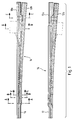
- Figure 1 shows a pair of rails 10, 12 which are extended by a switch 14 for guiding a convoy, either on the pair of rails 10a, 12a, or on the pair of rails 10b, 12b.
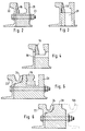
- the switch works in a conventional manner, only its manufacturing process and, consequently, the profile of the parts used is distinguished from the state of the art. This is illustrated by the different sections according to Figures 2 to 6.
- Figure 2 shows a cross section of a referral cradle 16 at the point of a needle 18.
- the cradle is formed by a body 20 and a needle rail 22 , bolted to each other, in several places using bolts 23.
- the body 20 is produced in accordance with the method proposed by patent LU 87.503, that is to say, by machining, preferably, by automatic milling under programmed control.
- the needle rail 22 to which the body 20 is bolted may be formed by rail 10, 10a or rail 12, 12b of the existing track or by a rut rail welded to the latter.
- the needle-guide rail 22 has its rut 24 as shown in FIGS. 5 and 6, while in the part of the switch where the needle 18 is movable to exercise its deflection functions, the rail 22 is devoid of its rut as shown in Figures 2 to 4.
- the head of rail 22 defines with an appropriate profile of the body 20 produced by milling a groove forming the housing of the needle 18.
- the needle rail 22 is also devoid of the foot adjacent to the body 20 to allow bolting of the latter on the rail 22.
- the removal of the foot of the rail 22 and its rut 24 can be made by milling or sawing.
- the invention therefore makes it possible to reduce a non-negligible part of the machining proposed in the aforementioned patent by taking advantage of the existence of the counter-needle rail 22, the operation of removing the rut 24 and the base of the rail being largely offset by the gain in machining.
- the machined body 20 may have, as in the aforementioned patent, an inner longitudinal groove, not shown, for the passage of the heating pipe.
- Figures 3 and 4 correspond to the same figures of the aforementioned patent and respectively show a vertical hole 28 through the body 20 for the evacuation of rainwater and rinsing and a horizontal bore 30 intended to receive the maneuvering means of the needle 18.
- Figure 5 shows a section at the end of the switch in the region where the needle 18 is wider and where it is connected to the rails of the track.
- Figure 6 shows a section at the junction with the rail 10b which, in order to be bolted to the body 20 and to the needle rail 22 is also devoid of its foot on the side adjacent to the body 20.
- the raw material for the production of the body 20 is a rolled, forged or molded bloom, the quality of the steel of which can be easily determined by the manufacturer of the switch. These blooms are preferably cut lengthwise and obliquely so as to be able to produce, using a single bloom, two referral bodies 20 in application of the teaching provided by the aforementioned patent. After machining, it is possible to subject the body 20 to a heat treatment, or to localized quenching to achieve surface hardening of the parts most exposed to stresses. It is also possible to perform surface reloading by welding to locally increase the resistance. In the event of wear of the needle rail 22, it is possible to cut the latter, to unbolt it from the body 20 and to replace it without requiring replacement of the body 20.
Landscapes
- Engineering & Computer Science (AREA)
- Mechanical Engineering (AREA)
- Architecture (AREA)
- Civil Engineering (AREA)
- Structural Engineering (AREA)
- Memory System Of A Hierarchy Structure (AREA)
- Heat Treatments In General, Especially Conveying And Cooling (AREA)
- Linear Motors (AREA)
- Electrical Discharge Machining, Electrochemical Machining, And Combined Machining (AREA)
- Push-Button Switches (AREA)
- Vending Machines For Individual Products (AREA)
- Bearings For Parts Moving Linearly (AREA)
- Train Traffic Observation, Control, And Security (AREA)
- Railway Tracks (AREA)
Description
- La présente invention concerne un aiguillage pour rails à gorge ou ornière constitué par un berceau profilé formant le logement d'une aiguille mobile de déviation, ainsi que les surfaces de roulement et de guidage et permettant la mise en place des moyens nécessaires à la manoeuvre de l'aiguille.
- L'invention vise plus particulièrement, sans y être limitée, des aiguillages pour les voies ferrées de transports urbains ou d'installations portuaires, dont les rails sont noyés dans le revêtement du réseau routier.
- Ces aiguillages étaient, jusqu'à présent, généralement réalisés par un assemblage de divers composants, de qualité et de forme différentes, fabriqués sur mesure, soit par moulage, soit par usinage et assemblés manuellement, le plus souvent par soudure.
- Le brevet LU 87.503 propose un nouveau procédé de fabrication d'aiguillages du type décrit ci-dessus et selon le préambule de la revendication unique annexée, qui est entièrement réalisé par un usinage exclusivement par enlèvement de copeaux. Ce procédé de fabrication d'aiguillages présente de nombreux avantages, dont l'un des plus importants est celui de pouvoir être réalisé automatiquement sous commande programmée.
- Le but de la présente invention est de prévoir un aiguillage perfectionné qui présente tous les avantages de l'aiguillage obtenus selon le brevet luxembourgeois précité mais qui, en outre, permet une amélioration du rendement et une réduction sensible des déchets d'usinage.
- Pour atteindre cet objectif, l'invention a pour objet un aiguillage selon la revendication unique annexée.
- Le temps d'usinage d'un tel aiguillage est sensiblement réduit, ce qui augmente la capacité de production. En outre, le traitement thermique avant l'assemblage des pièces constituantes est plus facile. Le reconditionnement est également plus facile, notamment par remplacement du rail contre-aiguille après usure. La taille des blocs d'acier nécessaire a l'usinage peut également être réduit.
- D'autres avantages et caractéristiques ressortiront de la description détaillée d'un mode de réalisation avantageux, présenté ci-dessous, à titre d'exemple, en référence aux figures annexées dans lesquelles:
- la Figure 1 montre une vue schématique en plan d'un aiguillage et
- les Figures 2 à 6 montrent les sections transversales suivant les plans de coupe sur la Figure 1 définis respectivement par A, B, C, D et E.
- La Figure 1 montre une paire de rails 10, 12 qui sont prolongés par un aiguillage 14 destiné à guider un convoi, soit sur la paire de rails 10a, 12a, soit sur la paire de rails 10b, 12b. L'aiguillage fonctionne de manière classique, seul son procédé de fabrication et, par voie de conséquence, le profil des pièces utilisées se distingue de l'état de la technique. Ceci est illustré par les différentes sections selon les Figures 2 à 6.
- La Figure 2 montre une coupe transversale d'un berceau 16 d'aiguillage au niveau de la pointe d'une aiguille 18. Comme représenté sur les Figures 2 à 6, le berceau est formé par un corps 20 et un rail contre-aiguille 22, boulonnés l'un à l'autre, à plusieurs endroits à l'aide de boulons 23.
- Le corps 20 est réalisé conformément au procédé proposé par le brevet LU 87.503, c'est-à-dire, par usinage, de préférence, par fraisage automatique sous commande programmée.
- Le rail contre-aiguille 22 auquel est boulonné le corps 20 peut être formé par le rail 10, 10a ou le rail 12, 12b de la voie existante ou par un rail à ornière soudé à ces derniers. En fin d'aiguillage, le rail contre-aiguille 22 dispose de son ornière 24 comme représenté sur les Figures 5 et 6, alors que dans la partie de l'aiguillage où l'aiguille 18 est mobile pour exercer ses fonctions de déviation, le rail 22 est dépourvu de son ornière comme représenté sur les Figures 2 à 4. Dans cette partie, la tête du rail 22 définit avec un profil approprié du corps 20 réalisé par un fraisage une gorge formant le logement de l'aiguille 18.
- Sur toute la longueur de l'aiguillage le rail contre-aiguille 22 est également dépourvu du pied adjacent au corps 20 pour permettre le boulonnage de celui-ci sur le rail 22. L'enlèvement du pied du rail 22 et de son ornière 24 peut être réalisé par fraisage ou sciage.
- L'invention permet donc de réduire une partie non négligeable de l'usinage proposé dans le brevet précité en profitant de l'existence du rail contre-aiguille 22, l'opération d'enlèvement de l'ornière 24 et du pied du rail étant largement compensée par le gain en usinage.
- Le corps usiné 20 peut présenter, comme dans le brevet précité une rainure longitudinale intérieure, non représentée, pour le passage de conduite de chauffage.
- Les Figures 3 et 4 correspondent aux mêmes figures du brevet précité et montrent respectivement un trou vertical 28 à travers le corps 20 servant à l'évacuation des eaux de pluie et de rinçage et un percement horizontal 30 destiné à recevoir les moyens de manoeuvre de l'aiguille 18.
- La Figure 5 représente une coupe en fin d'aiguillage dans la région où l'aiguille 18 est plus large et où elle est raccordée aux rails de la voie de roulement.
- La Figure 6 représente une section au niveau de la jonction avec le rail 10b qui, pour pouvoir être boulonné au corps 20 et au rail contre-aiguille 22 est également dépourvu de son pied sur le côté adjacent au corps 20.
- La partie de l'aiguillage prévue entre le rail 12 et ses prolongements 12a, 12b se présente de manière analogue à ce qui a été décrit ci-dessus.
- Comme pour le brevet précité, la matière première pour la réalisation du corps 20 est un bloom laminé, forgé ou moulé dont la qualité de l'acier peut être facilement déterminée par le fabricant de l'aiguillage. Ces blooms sont, de préférence, coupés dans le sens de leur longueur et obliquement de manière à pouvoir réaliser à l'aide d'un seul bloom deux corps d'aiguillage 20 en application de l'enseignement fourni par le brevet précité. Après l'usinage il est possible de soumettre le corps 20 à un traitement thermique, ou de trempe localisée pour réaliser un durcissement superficiel des parties les plus exposées aux sollicitations. Il est également possible d'effectuer des rechargements superficiels par- soudure pour augmenter localement la résistance. En cas d'usure du rail contre-aiguille 22 il est possible de découper celui-ci, de le déboulonner du corps 20 et de le remplacer sans nécessiter de remplacement du corps 20.
Claims (1)
- Aiguillage pour rails à gorge ou ornière constitué par un berceau profilé formant le logement d'une aiguille mobile de déviation (18), ainsi que les surfaces de roulement et de guidage, le berceau comportant un percement (30) permettant la mise en place des moyens nécessaires à la manoeuvre de l'aiguillage, ledit berceau comprenant une partie formant rail contre-aiguille (22) et un corps profilé (20) réalisé par usinage par enlèvement de copeaux, caractérisé en ce que le rail contre-aiguille (22) est constitué par un rail à ornière (22) boulonné sur le corps profilé (20), ledit rail étant dépourvu de son pied adjacent au corps profilé (20) sur toute la longueur dudit corps profilé pour permettre le boulonnage, ainsi que de son ornière (24) dans la partie de l'aiguillage dans laquelle l'aiguille (18) est mobile pour exercer ses fonctions de déviation.
Priority Applications (1)
| Application Number | Priority Date | Filing Date | Title |
|---|---|---|---|
| AT90125606T ATE86694T1 (de) | 1990-04-11 | 1990-12-27 | Weiche fuer rillenschienen. |
Applications Claiming Priority (2)
| Application Number | Priority Date | Filing Date | Title |
|---|---|---|---|
| LU87721A LU87721A1 (fr) | 1990-04-11 | 1990-04-11 | Aiguillage pour rails a gorge |
| LU87721 | 1990-04-11 |
Publications (2)
| Publication Number | Publication Date |
|---|---|
| EP0451367A1 EP0451367A1 (fr) | 1991-10-16 |
| EP0451367B1 true EP0451367B1 (fr) | 1993-03-10 |
Family
ID=19731228
Family Applications (1)
| Application Number | Title | Priority Date | Filing Date |
|---|---|---|---|
| EP90125606A Expired - Lifetime EP0451367B1 (fr) | 1990-04-11 | 1990-12-27 | Aiguillage pour rails à gorge |
Country Status (6)
| Country | Link |
|---|---|
| EP (1) | EP0451367B1 (fr) |
| AT (1) | ATE86694T1 (fr) |
| AU (1) | AU631733B2 (fr) |
| CA (1) | CA2035751C (fr) |
| DE (1) | DE69001072T2 (fr) |
| LU (1) | LU87721A1 (fr) |
Families Citing this family (3)
| Publication number | Priority date | Publication date | Assignee | Title |
|---|---|---|---|---|
| PL3505678T3 (pl) * | 2016-04-21 | 2022-03-28 | Iftec Gmbh & Co. Kg | Urządzenie zwrotnicowe i rozjazd szynowy |
| GB2559347B (en) * | 2017-02-01 | 2019-06-05 | Laight Designs Ltd | Vehicle Stand |
| DE102017109635A1 (de) * | 2017-05-04 | 2018-11-08 | Iftec Gmbh & Co.Kg | Zungeneinrichtung und Verfahren zur Herstellung einer Zungeneinrichtung |
Family Cites Families (5)
| Publication number | Priority date | Publication date | Assignee | Title |
|---|---|---|---|---|
| NL36115C (fr) * | 1900-01-01 | |||
| US4251042A (en) * | 1979-03-05 | 1981-02-17 | Abex Corporation | Railway double tongue switch |
| DE3343239C1 (de) * | 1983-11-30 | 1985-05-30 | Elektro-Thermit Gmbh, 1000 Berlin | Zungenvorrichtung fuer Rillenschienenweichen |
| AT390084B (de) * | 1988-05-20 | 1990-03-12 | Voest Alpine Maschinenbau | Weiche mit einem herzstueck mit beweglicher haupt- und beispitze |
| LU87503A1 (fr) * | 1989-04-21 | 1989-09-12 | Kihn Sarl | Procede de fabrication d'aiguillages pour rails a gorge et aiguillage monobloc realise par ce procede |
-
1990
- 1990-04-11 LU LU87721A patent/LU87721A1/fr unknown
- 1990-12-27 EP EP90125606A patent/EP0451367B1/fr not_active Expired - Lifetime
- 1990-12-27 AT AT90125606T patent/ATE86694T1/de not_active IP Right Cessation
- 1990-12-27 DE DE9090125606T patent/DE69001072T2/de not_active Expired - Fee Related
-
1991
- 1991-02-06 CA CA002035751A patent/CA2035751C/fr not_active Expired - Fee Related
- 1991-04-11 AU AU74299/91A patent/AU631733B2/en not_active Ceased
Also Published As
| Publication number | Publication date |
|---|---|
| CA2035751A1 (fr) | 1991-10-12 |
| LU87721A1 (fr) | 1990-12-11 |
| AU631733B2 (en) | 1992-12-03 |
| DE69001072T2 (de) | 1993-06-17 |
| DE69001072D1 (de) | 1993-04-15 |
| EP0451367A1 (fr) | 1991-10-16 |
| CA2035751C (fr) | 2001-12-25 |
| AU7429991A (en) | 1991-10-17 |
| ATE86694T1 (de) | 1993-03-15 |
Similar Documents
| Publication | Publication Date | Title |
|---|---|---|
| BE1004242A3 (fr) | Procede de fabrication d'aiguillages pour rails a gorge et aiguillage monobloc realise par ce procede. | |
| CA3014533C (fr) | Procede de revetement au laser commande par robot pour la reparation de structures de chemin de fer usees et/ou endommagees | |
| EP0451367B1 (fr) | Aiguillage pour rails à gorge | |
| EP0664184B1 (fr) | Rotule à haute résistance mécanique et procédé de fabrication | |
| EP0515708B1 (fr) | Aiguillage pour rails à gorge | |
| CN101698266B (zh) | 一种高炉开口钎头的制备方法 | |
| JP2019534943A (ja) | ダイカスト装置または押し出しプレスの構成部品のための工具鋼組成物 | |
| JPH0435269B2 (fr) | ||
| RU2100159C1 (ru) | Способ восстановления подпятника | |
| FR2694473A3 (fr) | Four de fusion à induction possédant une partie inférieure amovible. | |
| CN111590192A (zh) | 一种无缝钢轨的铝热焊方法 | |
| EP1455015A1 (fr) | Aiguille bi-métal pour aiguillages ferroviaires | |
| EP1053822A2 (fr) | Procédé pour l'assemblage par soudage de deux éléments en acier de forte teneur en carbone et outil de chauffage pour un tel procédé | |
| JP4397711B2 (ja) | 耐摩耗部の補修方法 | |
| KR20000012705A (ko) | 세그먼트 튜브의 브론즈 용접방법 | |
| CN204171565U (zh) | 一种新型的磨鞋的石墨制模具 | |
| BE900314A (fr) | Perfectionnement aux procedes d'oxycoupage d'un produit metallique. | |
| CN104259709B (zh) | 一种磨鞋、铣鞋或套铣筒的制造方法 | |
| SU941053A1 (ru) | Способ изготовлени корпуса железнодорожной автосцепки | |
| FR2704469A1 (fr) | Procédé de soudage bord à bord d'au moins deux flans de tôle. | |
| KR200209693Y1 (ko) | 이종금속의 마찰용접모재 | |
| Krasnosolov | Restoration of details-a second life of agricultural engineering | |
| FR2783446A1 (fr) | Outil de percement d'une lumiere dans un rail a gorge et procede de realisation de cette lumiere | |
| EP0079099A2 (fr) | Procédé de préparation de rail à gorge, rail ainsi obtenu et appareil de voie muni d'un tel rail | |
| US350152A (en) | pedder |
Legal Events
| Date | Code | Title | Description |
|---|---|---|---|
| PUAI | Public reference made under article 153(3) epc to a published international application that has entered the european phase |
Free format text: ORIGINAL CODE: 0009012 |
|
| AK | Designated contracting states |
Kind code of ref document: A1 Designated state(s): AT BE CH DE FR GB IT LI NL SE |
|
| 17P | Request for examination filed |
Effective date: 19920311 |
|
| 17Q | First examination report despatched |
Effective date: 19920529 |
|
| GRAA | (expected) grant |
Free format text: ORIGINAL CODE: 0009210 |
|
| AK | Designated contracting states |
Kind code of ref document: B1 Designated state(s): AT BE CH DE FR GB IT LI NL SE |
|
| REF | Corresponds to: |
Ref document number: 86694 Country of ref document: AT Date of ref document: 19930315 Kind code of ref document: T |
|
| REF | Corresponds to: |
Ref document number: 69001072 Country of ref document: DE Date of ref document: 19930415 |
|
| GBT | Gb: translation of ep patent filed (gb section 77(6)(a)/1977) |
Effective date: 19930324 |
|
| ITF | It: translation for a ep patent filed | ||
| PLBE | No opposition filed within time limit |
Free format text: ORIGINAL CODE: 0009261 |
|
| STAA | Information on the status of an ep patent application or granted ep patent |
Free format text: STATUS: NO OPPOSITION FILED WITHIN TIME LIMIT |
|
| 26N | No opposition filed | ||
| EAL | Se: european patent in force in sweden |
Ref document number: 90125606.5 |
|
| REG | Reference to a national code |
Ref country code: GB Ref legal event code: IF02 |
|
| PGFP | Annual fee paid to national office [announced via postgrant information from national office to epo] |
Ref country code: IT Payment date: 20061231 Year of fee payment: 17 |
|
| PGFP | Annual fee paid to national office [announced via postgrant information from national office to epo] |
Ref country code: BE Payment date: 20070125 Year of fee payment: 17 |
|
| PGFP | Annual fee paid to national office [announced via postgrant information from national office to epo] |
Ref country code: SE Payment date: 20070126 Year of fee payment: 17 |
|
| PGFP | Annual fee paid to national office [announced via postgrant information from national office to epo] |
Ref country code: NL Payment date: 20070129 Year of fee payment: 17 |
|
| PGFP | Annual fee paid to national office [announced via postgrant information from national office to epo] |
Ref country code: GB Payment date: 20070130 Year of fee payment: 17 |
|
| PGFP | Annual fee paid to national office [announced via postgrant information from national office to epo] |
Ref country code: DE Payment date: 20070131 Year of fee payment: 17 |
|
| PGFP | Annual fee paid to national office [announced via postgrant information from national office to epo] |
Ref country code: CH Payment date: 20070223 Year of fee payment: 17 Ref country code: AT Payment date: 20070223 Year of fee payment: 17 |
|
| REG | Reference to a national code |
Ref country code: CH Ref legal event code: PFA Owner name: KIHN S.A R.L. Free format text: KIHN S.A R.L.#17, RUE DE L'USINE#RUMELANGE (LU) -TRANSFER TO- KIHN S.A R.L.#17, RUE DE L'USINE#RUMELANGE (LU) |
|
| PGFP | Annual fee paid to national office [announced via postgrant information from national office to epo] |
Ref country code: FR Payment date: 20070129 Year of fee payment: 17 |
|
| BERE | Be: lapsed |
Owner name: *KIHN S.A.R.L. Effective date: 20071231 |
|
| REG | Reference to a national code |
Ref country code: CH Ref legal event code: PL |
|
| EUG | Se: european patent has lapsed | ||
| GBPC | Gb: european patent ceased through non-payment of renewal fee |
Effective date: 20071227 |
|
| PG25 | Lapsed in a contracting state [announced via postgrant information from national office to epo] |
Ref country code: AT Free format text: LAPSE BECAUSE OF NON-PAYMENT OF DUE FEES Effective date: 20071227 |
|
| NLV4 | Nl: lapsed or anulled due to non-payment of the annual fee |
Effective date: 20080701 |
|
| PG25 | Lapsed in a contracting state [announced via postgrant information from national office to epo] |
Ref country code: BE Free format text: LAPSE BECAUSE OF NON-PAYMENT OF DUE FEES Effective date: 20071231 |
|
| PG25 | Lapsed in a contracting state [announced via postgrant information from national office to epo] |
Ref country code: SE Free format text: LAPSE BECAUSE OF NON-PAYMENT OF DUE FEES Effective date: 20071228 Ref country code: CH Free format text: LAPSE BECAUSE OF NON-PAYMENT OF DUE FEES Effective date: 20071231 Ref country code: DE Free format text: LAPSE BECAUSE OF NON-PAYMENT OF DUE FEES Effective date: 20080701 Ref country code: LI Free format text: LAPSE BECAUSE OF NON-PAYMENT OF DUE FEES Effective date: 20071231 |
|
| REG | Reference to a national code |
Ref country code: FR Ref legal event code: ST Effective date: 20081020 |
|
| PG25 | Lapsed in a contracting state [announced via postgrant information from national office to epo] |
Ref country code: NL Free format text: LAPSE BECAUSE OF NON-PAYMENT OF DUE FEES Effective date: 20080701 |
|
| PG25 | Lapsed in a contracting state [announced via postgrant information from national office to epo] |
Ref country code: GB Free format text: LAPSE BECAUSE OF NON-PAYMENT OF DUE FEES Effective date: 20071227 |
|
| PG25 | Lapsed in a contracting state [announced via postgrant information from national office to epo] |
Ref country code: FR Free format text: LAPSE BECAUSE OF NON-PAYMENT OF DUE FEES Effective date: 20071231 |
|
| PG25 | Lapsed in a contracting state [announced via postgrant information from national office to epo] |
Ref country code: IT Free format text: LAPSE BECAUSE OF NON-PAYMENT OF DUE FEES Effective date: 20071227 |