EP0451382B1 - Gestreifter Lichtstreukörper und dessen Herstellungsmethode - Google Patents
Gestreifter Lichtstreukörper und dessen Herstellungsmethode Download PDFInfo
- Publication number
- EP0451382B1 EP0451382B1 EP90303857A EP90303857A EP0451382B1 EP 0451382 B1 EP0451382 B1 EP 0451382B1 EP 90303857 A EP90303857 A EP 90303857A EP 90303857 A EP90303857 A EP 90303857A EP 0451382 B1 EP0451382 B1 EP 0451382B1
- Authority
- EP
- European Patent Office
- Prior art keywords
- light
- fiber
- optical fibers
- axis
- along
- Prior art date
- Legal status (The legal status is an assumption and is not a legal conclusion. Google has not performed a legal analysis and makes no representation as to the accuracy of the status listed.)
- Expired - Lifetime
Links
- 238000000034 method Methods 0.000 title description 6
- 239000013307 optical fiber Substances 0.000 claims description 29
- 238000004519 manufacturing process Methods 0.000 claims description 6
- 238000010438 heat treatment Methods 0.000 claims 1
- 239000000835 fiber Substances 0.000 description 33
- 230000005855 radiation Effects 0.000 description 7
- 230000004907 flux Effects 0.000 description 5
- 230000007423 decrease Effects 0.000 description 4
- 238000007788 roughening Methods 0.000 description 4
- 239000004925 Acrylic resin Substances 0.000 description 3
- 229920000178 Acrylic resin Polymers 0.000 description 3
- 239000002131 composite material Substances 0.000 description 3
- 244000025254 Cannabis sativa Species 0.000 description 2
- 235000012766 Cannabis sativa ssp. sativa var. sativa Nutrition 0.000 description 2
- 235000012765 Cannabis sativa ssp. sativa var. spontanea Nutrition 0.000 description 2
- 239000004809 Teflon Substances 0.000 description 2
- 229920006362 Teflon® Polymers 0.000 description 2
- 235000009120 camo Nutrition 0.000 description 2
- 235000005607 chanvre indien Nutrition 0.000 description 2
- 230000000052 comparative effect Effects 0.000 description 2
- 238000009826 distribution Methods 0.000 description 2
- 229910052736 halogen Inorganic materials 0.000 description 2
- 150000002367 halogens Chemical class 0.000 description 2
- 239000011487 hemp Substances 0.000 description 2
- 230000002093 peripheral effect Effects 0.000 description 2
- 230000001902 propagating effect Effects 0.000 description 2
- XLYOFNOQVPJJNP-UHFFFAOYSA-N water Substances O XLYOFNOQVPJJNP-UHFFFAOYSA-N 0.000 description 2
- 240000008415 Lactuca sativa Species 0.000 description 1
- 230000003247 decreasing effect Effects 0.000 description 1
- 230000000694 effects Effects 0.000 description 1
- 239000003822 epoxy resin Substances 0.000 description 1
- 239000011521 glass Substances 0.000 description 1
- 239000005457 ice water Substances 0.000 description 1
- 238000009828 non-uniform distribution Methods 0.000 description 1
- 239000011022 opal Substances 0.000 description 1
- 238000012856 packing Methods 0.000 description 1
- 230000000243 photosynthetic effect Effects 0.000 description 1
- 229920000647 polyepoxide Polymers 0.000 description 1
- 235000012045 salad Nutrition 0.000 description 1
- 229910001220 stainless steel Inorganic materials 0.000 description 1
- 239000010935 stainless steel Substances 0.000 description 1
Images
Classifications
-
- G—PHYSICS
- G02—OPTICS
- G02B—OPTICAL ELEMENTS, SYSTEMS OR APPARATUS
- G02B5/00—Optical elements other than lenses
- G02B5/02—Diffusing elements; Afocal elements
- G02B5/0205—Diffusing elements; Afocal elements characterised by the diffusing properties
- G02B5/021—Diffusing elements; Afocal elements characterised by the diffusing properties the diffusion taking place at the element's surface, e.g. by means of surface roughening or microprismatic structures
- G02B5/0215—Diffusing elements; Afocal elements characterised by the diffusing properties the diffusion taking place at the element's surface, e.g. by means of surface roughening or microprismatic structures the surface having a regular structure
-
- G—PHYSICS
- G02—OPTICS
- G02B—OPTICAL ELEMENTS, SYSTEMS OR APPARATUS
- G02B5/00—Optical elements other than lenses
- G02B5/02—Diffusing elements; Afocal elements
- G02B5/0268—Diffusing elements; Afocal elements characterized by the fabrication or manufacturing method
-
- G—PHYSICS
- G02—OPTICS
- G02B—OPTICAL ELEMENTS, SYSTEMS OR APPARATUS
- G02B5/00—Optical elements other than lenses
- G02B5/02—Diffusing elements; Afocal elements
- G02B5/0273—Diffusing elements; Afocal elements characterized by the use
- G02B5/0284—Diffusing elements; Afocal elements characterized by the use used in reflection
-
- G—PHYSICS
- G02—OPTICS
- G02B—OPTICAL ELEMENTS, SYSTEMS OR APPARATUS
- G02B6/00—Light guides; Structural details of arrangements comprising light guides and other optical elements, e.g. couplings
- G02B6/04—Light guides; Structural details of arrangements comprising light guides and other optical elements, e.g. couplings formed by bundles of fibres
-
- G—PHYSICS
- G02—OPTICS
- G02B—OPTICAL ELEMENTS, SYSTEMS OR APPARATUS
- G02B6/00—Light guides; Structural details of arrangements comprising light guides and other optical elements, e.g. couplings
- G02B6/0001—Light guides; Structural details of arrangements comprising light guides and other optical elements, e.g. couplings specially adapted for lighting devices or systems
Definitions
- the present invention relates to an elongated structure for receiving light through an end or edge thereof, and radiating or diffusing the light out through a surface of the structure which is substantially perpendicular to the end or edge through which the light was introduced.
- the invention also relates to a method for manufacturing such a structure.
- a conventional optical fiber or light pipe is designed to transmit light introduced into one end thereof to an opposite end with minimum loss of light through the circumferential surface of the fiber. This is possible since light entering the end of the fiber at an angle less than the numerical aperture of the fiber is totally internally reflected throughout the length of the fiber to the other end.
- an optical fiber to radiate or diffuse light introduced into an end thereof from a point light source out through the circumferential or peripheral surface thereof, and thereby function as an elongated light source in combination with the point light source.
- a partially transparent, or translucent optical fiber such as "opal" glass made of acrylic resin by the Asahi Chemical Co. of Japan also radiates light out the circumferential surface thereof.
- the expedients of making an optical fiber translucent, or roughening the circumferential surface of an optical fiber to produce light radiation out through the surface thereof are generally unsatisfactory in that the intensity of the radiated light decreases exponentially from the input end along the longitudinal axis of the fiber.
- a third method of producing light radiation out the circumferential surface of an optical fiber is to make a series of small cuts in the surface thereof. This expedient is also unsatisfactory in that the radiated light intensity is discontinuous and uneven along the length of the fiber.
- modified optical fibers known in the prior art are not usable in practical applications such as back lights for displays, panel lights, and linear light radiators for photosynthetic reactors which require an even distribution of radiated light along the length of the radiating surface.
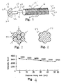
- a light radiating or diffusing structure embodying the present invention including a body in the form of an optical fiber is generally designated as 10, and has a longitudinal axis 12 and a peripheral or circumferential surface 14 which extends parallel to the axis 12.
- the fiber 10 has a circular cross section centered on the axis 12.
- a plurality of longitudinal striations 16 are formed in the circumferential surface 14 parallel to the axis 12.
- a light source 18 includes, for example, a point light source in the form a halogen bulb 20 mounted in a housing 22.
- a reflector 24 directs the light from the bulb 20 into a light guide 26 which transmits the light into an input face or end 28 of the optical fiber 10 along the longitudinal axis 12 thereof.
- the light propagates through the fiber 10 along the axis 12 as indicated by an arrow 30. Due to internal reflections in the optical fiber 10 which are affected by the striations 16, the light is progressively radiated out of the circumferential surface 14 of the fiber 10 along the axis 12 in directions indicated by arrows 32, and also in directions 32' if the end of the fiber 10 opposite the end 28 is made reflective.
- the intensity of light radiated out the circumferential surface 14 is substantially uniform along the axis 12.
- the present longitudinal striations affect the internal reflection of light by creating additional reflections between the walls of adjacent striations. Each of these additional reflections causes the angle of incidence of the respective light rays to increase relative to the circumferential surface of the fiber. At a certain distance along the fiber, the angle of incidence of a given light ray will be increased by these multiple reflections beyond the angle of total internal reflection of the fiber, and be radiated out the circumferential surface of the fiber. The effect is essentially similar for the case of a panel structure formed with longitudinal striations. The exact mechanism by which the composite reflections interact with each other is complex and not fully understood.
- the amount of radiation increase or decrease along the length of the structure. This can be accomplished by tapering the structure (diameter of an optical fiber or thickness of a panel) in the desired direction of non-uniform distribution, or by varying the number, width, and/or depth of the striations. Reducing the thickness of the structure increases the overall angle of internal reflection and thereby the amount of radiated light. Increasing the width and/or depth of the striations increases the amount of radiated light.
- FIGs. 2 and 3 A method of fabricating an optical fiber in acccordance with the present invention is illustrated in FIGs. 2 and 3.
- a plurality of optical fibers 90 are bundled together as illustrated in FIG. 2, and subjected to heat and radial pressure.
- the ends of the bundle are preferably restrained to prevent shrinkage of the fibers 90.
- the temperature, pressure, and length of time of application thereof are selected such that the individual fibers 90 fuse together to form a composite optical fiber 92 illustrated in FIG. 2.
- the striations are constituted by external surfaces 94 of the individual fibers 90 which did not fuse together into the mass of the composite fiber 92.
- Light was introduced into one end of the resulting structure using a light source 18 including a 150 W halogen lamp 20 such as illustrated in FIG. 1.
- the light radiated out of the circumferential surface of the structure was visually observed to be substantially uniform over the length of the structure, except for approximately the first 15 cm from the light receiving end.
- Three stainless steel tanks which were 1000 mm long, 100 mm wide, and 50mm high were provided.
- a 1000 mm long x 100 mm wide, 800 W sheet rubber heater was glued to the bottom of one of the tanks.
- the tank to which the heater was attached was enclosed in a wooden box.
- This tank was filled with salad oil, and heated to 142 ⁇ 1°C.
- the other two tanks were filled with ice water, and maintained at a temperature of 5°C or lower.
- An acrylic resin optical fiber with a diameter of 1mm and a length of 1000 mm was immersed in one of the cold water tanks for approximately one minute. Then, approximately the center 600 mm of the fiber was immersed in the hot oil tank for approximately 3 seconds, with the ends of the fiber being clamped to prevent shrinkage of the fiber. Finally, the fiber was immersed in the other cold water tank for approximately 30 seconds. As a result, a plurality of longitudinal striations were formed on the surface of the fiber.
- the light source used in EXAMPLE 1 was used to introduce light into one end of the fiber.
- the amount of luminous flux entering the fiber was measured to be 8.8 1m.
- the distribution of radiated light intensity along the center 60 mm in which the striations were formed is illustrated in FIG. 4.
- the amount of luminous flux radiated from the entire circumferential surface of the fiber was measured to be 5.3 lm. This amount was confirmed by converting the measured light intensity in FIG. 15 into luminous flux.
- the amount of luminous flux radiated from the opposite end of the fiber was measured to be 3.5 lm.
- approximately 60% of the luminous flux which entered the fiber was consumed along the striated portion, and approximately 100% of the consumed light was radiated out the surface of the fiber in the striated portion.
Landscapes
- Physics & Mathematics (AREA)
- General Physics & Mathematics (AREA)
- Optics & Photonics (AREA)
- Engineering & Computer Science (AREA)
- Manufacturing & Machinery (AREA)
- Light Guides In General And Applications Therefor (AREA)
- Optical Fibers, Optical Fiber Cores, And Optical Fiber Bundles (AREA)
Claims (2)
- Lichtausstrahlende Vorrichtung mit:einem lichtausstrahlenden Körper (10), (40) mit einer Längsachse (12), (42) und einer lichtausstrahlenden Umfangsfläche (14) aufweist, welche sich im wesentlichen parallel zu der Achse (12) erstreckt; undeiner Mehrzahl von Rippen (16), welche in der Oberfläche (14) ausgebildet sind und sich derart parallel zu der Achse (12) erstrecken, daß in den Körper (10) entlang der Achse (12) hineingeführtes Licht aus dem Körper (10) durch die Oberfläche (14) hindurch mit im wesentlichen entlang der Achse (12) gleichbleibender Intensität ausgestrahlt wird, wobeider Körper (10) einen im wesentlichen kreisförmigen Querschnitt aufweist, dessen Mitte von der Achse (12) ausgebildet wird, und die lichtausstrahlende Oberfläche (14) die Gestalt einer Umfangs-Oberfläche (14) aufweist, und wobeider Körper (10) ein derart zusammengeschmolzenes Bündel von optischen Fasern (90) aufweist, daß die freiliegenden Abschnitte (94) der optischen Fasern (90) die Rippen (16) ausbilden.
- Verfahren zum Herstellen einer lichtausstrahlenden Vorrichtung nach Anspruch 1, mit den Verfahrensschritten:(a) Bereitstellen einer Mehrzahl von optischen Fasern (90);(b) Zusammenbündeln der optischen Fasern (90); und(c) Erwärmen der optischen Fasern (90) auf eine derart ausgewählte Temperatur und über einen derart ausgewählten Zeitraum, daß die optischen Fasern (90) derart miteinander verschmelzen, daß die freiliegenden Abschnitte (94) der zusammengeschmolzenen Fasern (90) lichtausstrahlende Längsrippen (94) ausbilden.
Priority Applications (8)
| Application Number | Priority Date | Filing Date | Title |
|---|---|---|---|
| DE69032973T DE69032973T2 (de) | 1990-04-10 | 1990-04-10 | Gestreifter Lichtstreukörper und dessen Herstellungsmethode |
| EP98115295A EP0903593B1 (de) | 1990-04-10 | 1990-04-10 | Gestreifter Lichtstreukörper und Herstellungsmethode dafür |
| EP90303857A EP0451382B1 (de) | 1990-04-10 | 1990-04-10 | Gestreifter Lichtstreukörper und dessen Herstellungsmethode |
| ES98115295T ES2277372T3 (es) | 1990-04-10 | 1990-04-10 | Difusor estriado de luz y metodo para su fabricacion. |
| CA002014309A CA2014309C (en) | 1990-04-10 | 1990-04-10 | Striated light diffuser and method of forming the same |
| AT90303857T ATE177211T1 (de) | 1990-04-10 | 1990-04-10 | Gestreifter lichtstreukörper und dessen herstellungsmethode |
| AU53167/90A AU619103B2 (en) | 1990-04-10 | 1990-04-11 | Striated light diffuser and method of forming the same |
| US07/866,007 US5233679A (en) | 1990-04-10 | 1992-04-09 | Striated light diffuser and method of forming the same |
Applications Claiming Priority (2)
| Application Number | Priority Date | Filing Date | Title |
|---|---|---|---|
| EP90303857A EP0451382B1 (de) | 1990-04-10 | 1990-04-10 | Gestreifter Lichtstreukörper und dessen Herstellungsmethode |
| CA002014309A CA2014309C (en) | 1990-04-10 | 1990-04-10 | Striated light diffuser and method of forming the same |
Related Child Applications (1)
| Application Number | Title | Priority Date | Filing Date |
|---|---|---|---|
| EP98115295A Division EP0903593B1 (de) | 1990-04-10 | 1990-04-10 | Gestreifter Lichtstreukörper und Herstellungsmethode dafür |
Publications (2)
| Publication Number | Publication Date |
|---|---|
| EP0451382A1 EP0451382A1 (de) | 1991-10-16 |
| EP0451382B1 true EP0451382B1 (de) | 1999-03-03 |
Family
ID=25674063
Family Applications (1)
| Application Number | Title | Priority Date | Filing Date |
|---|---|---|---|
| EP90303857A Expired - Lifetime EP0451382B1 (de) | 1990-04-10 | 1990-04-10 | Gestreifter Lichtstreukörper und dessen Herstellungsmethode |
Country Status (3)
| Country | Link |
|---|---|
| EP (1) | EP0451382B1 (de) |
| AU (1) | AU619103B2 (de) |
| CA (1) | CA2014309C (de) |
Families Citing this family (2)
| Publication number | Priority date | Publication date | Assignee | Title |
|---|---|---|---|---|
| PL232512B1 (pl) * | 2017-07-10 | 2019-06-28 | Fibrain Spolka Z Ograniczona Odpowiedzialnoscia | Sposób wytwarzania dyfuzora światłowodowego i dyfuzor światłowodowy wytworzony tym sposobem |
| CN112147786B (zh) * | 2020-10-28 | 2024-04-12 | 南京爱奇艺智能科技有限公司 | 一种增强现实显示系统 |
Citations (1)
| Publication number | Priority date | Publication date | Assignee | Title |
|---|---|---|---|---|
| US4422719A (en) * | 1981-05-07 | 1983-12-27 | Space-Lyte International, Inc. | Optical distribution system including light guide |
Family Cites Families (8)
| Publication number | Priority date | Publication date | Assignee | Title |
|---|---|---|---|---|
| DE1203310B (de) * | 1961-06-24 | 1965-10-21 | Saba Gmbh | Verfahren zum Profilieren einer der Herstellung von optischen Blenden mit Rillenprofil dienenden Walze |
| US3829675A (en) * | 1973-04-30 | 1974-08-13 | R Mariani | Lighting means for underwater illumination |
| DE2827573C2 (de) * | 1978-06-23 | 1983-02-03 | Blaupunkt-Werke Gmbh, 3200 Hildesheim | Großflächige Lichtquelle |
| US4615579A (en) * | 1983-08-29 | 1986-10-07 | Canadian Patents & Development Ltd. | Prism light guide luminaire |
| EP0152493B1 (de) * | 1984-02-02 | 1988-07-27 | Kei Mori | Leuchte |
| CA1279783C (en) * | 1985-11-21 | 1991-02-05 | Minnesota Mining And Manufacturing Company | Totally internally reflecting thin, flexible film |
| CA1268969A (en) * | 1986-01-15 | 1990-05-15 | Sanford Cobb, Jr. | Totally internally reflecting light conduit |
| JPH0614162Y2 (ja) * | 1987-06-19 | 1994-04-13 | 三菱レイヨン株式会社 | 光フアイバ粗面加工装置 |
-
1990
- 1990-04-10 CA CA002014309A patent/CA2014309C/en not_active Expired - Lifetime
- 1990-04-10 EP EP90303857A patent/EP0451382B1/de not_active Expired - Lifetime
- 1990-04-11 AU AU53167/90A patent/AU619103B2/en not_active Expired
Patent Citations (1)
| Publication number | Priority date | Publication date | Assignee | Title |
|---|---|---|---|---|
| US4422719A (en) * | 1981-05-07 | 1983-12-27 | Space-Lyte International, Inc. | Optical distribution system including light guide |
Also Published As
| Publication number | Publication date |
|---|---|
| EP0451382A1 (de) | 1991-10-16 |
| CA2014309C (en) | 1995-09-05 |
| AU619103B2 (en) | 1992-01-16 |
| AU5316790A (en) | 1991-10-17 |
Similar Documents
| Publication | Publication Date | Title |
|---|---|---|
| US5233679A (en) | Striated light diffuser and method of forming the same | |
| US4466697A (en) | Light dispersive optical lightpipes and method of making the same | |
| US5021928A (en) | Flat panel illumination system | |
| US5183323A (en) | Flat panel illumination system | |
| AU619591B2 (en) | Light emitting panel assemblies and method of making same | |
| CA2200441C (en) | Hollow light guide for diffuse light | |
| US4585298A (en) | Photoradiator for radiating light | |
| US5042900A (en) | Connector assemblies for optical fiber light cables | |
| US5222795A (en) | Controlled light extraction from light guides and fibers | |
| CA2201795C (en) | Lighting system | |
| CN1157616C (zh) | 采用多层光学薄膜的光波导 | |
| US4885663A (en) | Fiber optic light emitting panel and method of making same | |
| US5371826A (en) | Dental fiber optic light bundle with uniform taper | |
| US6137928A (en) | Optical fiber light distribution system and method of manufacture and illumination | |
| AU575196B2 (en) | A fibre-optic cable responsive to microbending forces | |
| US4933815A (en) | Light pipe for decorative illumination | |
| JPH04249203A (ja) | パネル照明器 | |
| US8031998B2 (en) | Illumination fiber optic ribbon | |
| US5060119A (en) | Light pipe for decorative illumination | |
| EP0451382B1 (de) | Gestreifter Lichtstreukörper und dessen Herstellungsmethode | |
| US5372756A (en) | Method of forming striated light diffuser | |
| JPS5937501A (ja) | 光ラジエ−タ | |
| EP0903593B1 (de) | Gestreifter Lichtstreukörper und Herstellungsmethode dafür | |
| KR19980023990A (ko) | 조명 시스템 | |
| CN120535217A (zh) | 一种基于涂覆工艺的侧面发光玻璃光纤制备方法及其产品 |
Legal Events
| Date | Code | Title | Description |
|---|---|---|---|
| PUAI | Public reference made under article 153(3) epc to a published international application that has entered the european phase |
Free format text: ORIGINAL CODE: 0009012 |
|
| AK | Designated contracting states |
Kind code of ref document: A1 Designated state(s): AT BE CH DE DK ES FR GB GR IT LI LU NL SE |
|
| 17P | Request for examination filed |
Effective date: 19920325 |
|
| 17Q | First examination report despatched |
Effective date: 19931129 |
|
| GRAG | Despatch of communication of intention to grant |
Free format text: ORIGINAL CODE: EPIDOS AGRA |
|
| GRAG | Despatch of communication of intention to grant |
Free format text: ORIGINAL CODE: EPIDOS AGRA |
|
| GRAH | Despatch of communication of intention to grant a patent |
Free format text: ORIGINAL CODE: EPIDOS IGRA |
|
| GRAH | Despatch of communication of intention to grant a patent |
Free format text: ORIGINAL CODE: EPIDOS IGRA |
|
| GRAA | (expected) grant |
Free format text: ORIGINAL CODE: 0009210 |
|
| AK | Designated contracting states |
Kind code of ref document: B1 Designated state(s): AT BE CH DE DK ES FR GB GR IT LI LU NL SE |
|
| PG25 | Lapsed in a contracting state [announced via postgrant information from national office to epo] |
Ref country code: IT Free format text: LAPSE BECAUSE OF FAILURE TO SUBMIT A TRANSLATION OF THE DESCRIPTION OR TO PAY THE FEE WITHIN THE PRE;WARNING: LAPSES OF ITALIAN PATENTS WITH EFFECTIVE DATE BEFORE 2007 MAY HAVE OCCURRED AT ANY TIME BEFORE 2007. THE CORRECT EFFECTIVE DATE MAY BE DIFFERENT FROM THE ONE RECORDED.SCRIBED TIME-LIMIT Effective date: 19990303 Ref country code: BE Free format text: LAPSE BECAUSE OF FAILURE TO SUBMIT A TRANSLATION OF THE DESCRIPTION OR TO PAY THE FEE WITHIN THE PRESCRIBED TIME-LIMIT Effective date: 19990303 Ref country code: ES Free format text: THE PATENT HAS BEEN ANNULLED BY A DECISION OF A NATIONAL AUTHORITY Effective date: 19990303 Ref country code: CH Free format text: LAPSE BECAUSE OF FAILURE TO SUBMIT A TRANSLATION OF THE DESCRIPTION OR TO PAY THE FEE WITHIN THE PRESCRIBED TIME-LIMIT Effective date: 19990303 Ref country code: GR Free format text: LAPSE BECAUSE OF NON-PAYMENT OF DUE FEES Effective date: 19990303 Ref country code: LI Free format text: LAPSE BECAUSE OF FAILURE TO SUBMIT A TRANSLATION OF THE DESCRIPTION OR TO PAY THE FEE WITHIN THE PRESCRIBED TIME-LIMIT Effective date: 19990303 Ref country code: NL Free format text: LAPSE BECAUSE OF FAILURE TO SUBMIT A TRANSLATION OF THE DESCRIPTION OR TO PAY THE FEE WITHIN THE PRESCRIBED TIME-LIMIT Effective date: 19990303 Ref country code: SE Free format text: THE PATENT HAS BEEN ANNULLED BY A DECISION OF A NATIONAL AUTHORITY Effective date: 19990303 Ref country code: AT Free format text: LAPSE BECAUSE OF FAILURE TO SUBMIT A TRANSLATION OF THE DESCRIPTION OR TO PAY THE FEE WITHIN THE PRESCRIBED TIME-LIMIT Effective date: 19990303 |
|
| REF | Corresponds to: |
Ref document number: 177211 Country of ref document: AT Date of ref document: 19990315 Kind code of ref document: T |
|
| REG | Reference to a national code |
Ref country code: CH Ref legal event code: EP |
|
| REF | Corresponds to: |
Ref document number: 69032973 Country of ref document: DE Date of ref document: 19990408 |
|
| PG25 | Lapsed in a contracting state [announced via postgrant information from national office to epo] |
Ref country code: LU Free format text: LAPSE BECAUSE OF NON-PAYMENT OF DUE FEES Effective date: 19990410 |
|
| PG25 | Lapsed in a contracting state [announced via postgrant information from national office to epo] |
Ref country code: DK Free format text: LAPSE BECAUSE OF FAILURE TO SUBMIT A TRANSLATION OF THE DESCRIPTION OR TO PAY THE FEE WITHIN THE PRESCRIBED TIME-LIMIT Effective date: 19990603 |
|
| ET | Fr: translation filed | ||
| NLV1 | Nl: lapsed or annulled due to failure to fulfill the requirements of art. 29p and 29m of the patents act | ||
| REG | Reference to a national code |
Ref country code: CH Ref legal event code: PL |
|
| PLBE | No opposition filed within time limit |
Free format text: ORIGINAL CODE: 0009261 |
|
| STAA | Information on the status of an ep patent application or granted ep patent |
Free format text: STATUS: NO OPPOSITION FILED WITHIN TIME LIMIT |
|
| 26N | No opposition filed | ||
| REG | Reference to a national code |
Ref country code: GB Ref legal event code: IF02 |
|
| REG | Reference to a national code |
Ref country code: FR Ref legal event code: CA |
|
| PGFP | Annual fee paid to national office [announced via postgrant information from national office to epo] |
Ref country code: FR Payment date: 20080418 Year of fee payment: 19 |
|
| PGFP | Annual fee paid to national office [announced via postgrant information from national office to epo] |
Ref country code: GB Payment date: 20080423 Year of fee payment: 19 |
|
| PGFP | Annual fee paid to national office [announced via postgrant information from national office to epo] |
Ref country code: DE Payment date: 20081031 Year of fee payment: 19 |
|
| GBPC | Gb: european patent ceased through non-payment of renewal fee |
Effective date: 20090410 |
|
| REG | Reference to a national code |
Ref country code: FR Ref legal event code: ST Effective date: 20091231 |
|
| PG25 | Lapsed in a contracting state [announced via postgrant information from national office to epo] |
Ref country code: DE Free format text: LAPSE BECAUSE OF NON-PAYMENT OF DUE FEES Effective date: 20091103 |
|
| PG25 | Lapsed in a contracting state [announced via postgrant information from national office to epo] |
Ref country code: GB Free format text: LAPSE BECAUSE OF NON-PAYMENT OF DUE FEES Effective date: 20090410 Ref country code: FR Free format text: LAPSE BECAUSE OF NON-PAYMENT OF DUE FEES Effective date: 20091222 |