EP0451386A1 - Datenaufzeichnung - Google Patents
Datenaufzeichnung Download PDFInfo
- Publication number
- EP0451386A1 EP0451386A1 EP90303876A EP90303876A EP0451386A1 EP 0451386 A1 EP0451386 A1 EP 0451386A1 EP 90303876 A EP90303876 A EP 90303876A EP 90303876 A EP90303876 A EP 90303876A EP 0451386 A1 EP0451386 A1 EP 0451386A1
- Authority
- EP
- European Patent Office
- Prior art keywords
- data
- properties
- values
- recording medium
- recordation
- Prior art date
- Legal status (The legal status is an assumption and is not a legal conclusion. Google has not performed a legal analysis and makes no representation as to the accuracy of the status listed.)
- Granted
Links
- 238000013500 data storage Methods 0.000 title claims description 9
- 238000000034 method Methods 0.000 claims abstract description 12
- 230000003287 optical effect Effects 0.000 claims description 28
- 238000013139 quantization Methods 0.000 claims description 2
- 230000003595 spectral effect Effects 0.000 claims 3
- 238000001228 spectrum Methods 0.000 claims 2
- 239000013598 vector Substances 0.000 description 13
- 238000012545 processing Methods 0.000 description 5
- 230000005540 biological transmission Effects 0.000 description 3
- 239000000839 emulsion Substances 0.000 description 3
- 230000004907 flux Effects 0.000 description 3
- 238000001093 holography Methods 0.000 description 3
- 238000013459 approach Methods 0.000 description 2
- 230000008859 change Effects 0.000 description 2
- 239000003086 colorant Substances 0.000 description 2
- 238000007689 inspection Methods 0.000 description 2
- 230000008569 process Effects 0.000 description 2
- 230000002730 additional effect Effects 0.000 description 1
- 230000008901 benefit Effects 0.000 description 1
- 229910002056 binary alloy Inorganic materials 0.000 description 1
- 238000006243 chemical reaction Methods 0.000 description 1
- 150000001875 compounds Chemical group 0.000 description 1
- 230000008602 contraction Effects 0.000 description 1
- 238000007796 conventional method Methods 0.000 description 1
- 230000000694 effects Effects 0.000 description 1
- 238000005516 engineering process Methods 0.000 description 1
- 230000006870 function Effects 0.000 description 1
- 238000012886 linear function Methods 0.000 description 1
- 239000011159 matrix material Substances 0.000 description 1
- 230000010287 polarization Effects 0.000 description 1
- 230000001105 regulatory effect Effects 0.000 description 1
- 239000004065 semiconductor Substances 0.000 description 1
- 229910052709 silver Inorganic materials 0.000 description 1
- 239000004332 silver Substances 0.000 description 1
- -1 silver halide Chemical class 0.000 description 1
- 230000001960 triggered effect Effects 0.000 description 1
Images



Classifications
-
- G—PHYSICS
- G11—INFORMATION STORAGE
- G11B—INFORMATION STORAGE BASED ON RELATIVE MOVEMENT BETWEEN RECORD CARRIER AND TRANSDUCER
- G11B7/00—Recording or reproducing by optical means, e.g. recording using a thermal beam of optical radiation by modifying optical properties or the physical structure, reproducing using an optical beam at lower power by sensing optical properties; Record carriers therefor
- G11B7/004—Recording, reproducing or erasing methods; Read, write or erase circuits therefor
- G11B7/0065—Recording, reproducing or erasing by using optical interference patterns, e.g. holograms
-
- G—PHYSICS
- G03—PHOTOGRAPHY; CINEMATOGRAPHY; ANALOGOUS TECHNIQUES USING WAVES OTHER THAN OPTICAL WAVES; ELECTROGRAPHY; HOLOGRAPHY
- G03H—HOLOGRAPHIC PROCESSES OR APPARATUS
- G03H1/00—Holographic processes or apparatus using light, infrared or ultraviolet waves for obtaining holograms or for obtaining an image from them; Details peculiar thereto
- G03H1/26—Processes or apparatus specially adapted to produce multiple sub- holograms or to obtain images from them, e.g. multicolour technique
Definitions
- the present invention relates to a method and apparatus for the representation, storage and transmission of digital data, and in particular but not exclusively relates to high capacity data storage and retrieval.
- a 16 bit word can represent integer numbers from -32,767 to +32,767.
- Text characters like alphabetic upper and lower-case letters, are represented by standardized values of an eight bit storage unit known as the "byte".
- U.S. Patent 3,969,593 discloses an optical sound recording system for use with motion picture film, in which independent sound channels may be recorded on the same track by using hue variations in superimposed, but different colours. These approaches thereby provide recording systems wherein information is stored via the variations in discretely separate, varying parameters.
- Holography provides another approach to digital data recording. An overview of this technology is given in Handbook of Optical Holography (Ed. Caulfield, A.J., Academic Press Inc. 1979, Chap. 10). This storage method typically provides a set of superimposed "pages", wherein each page is a two-dimensional matrix of binary digital cells.
- storage capacity is simply a linear function of bit density.
- storage capacity increases exponentially with the additional of each recording vector. Since each vector can reside in one of the variety of states, the representational power of each storage unit is equal to the product of the number of states in which each vector can reside, thereby yielding the exponential relationship.
- the multiplexed quantization of these aforementioned systems can be characterized as non-logarithmic, in that each vector of one multiplexed storage unit can exist in one state. Therefore, just one value can be recorded on each vector of each multiplexed unit.
- the value of the recorded flux change is either positive or negative at the location of interest.
- each colour has a single hue value at a given location on the film.
- a digital data representation system comprising of a method for converting an incoming unit of text or numerical data into a hierarchical series of values, each of which is associated with a particular variable vector of the storage medium.
- data representation system will be used to denote a system which prepares data for storage on a medium.
- the hierarchical series of values are then stored in a multiplexed manner at a single physical storage location on the recording medium.
- Storage is accomplished by imparting to the storage location a total characteristic which is a combination of superimposed dissimilar and separately detectable vectors, each having a respective value.
- Recordation is by means of a holographic recording technique wherein a sequence of incoming units of data are stored as a sequence of multiplexed holographic spots or bits on the recording media.
- bit the basic unit or location of data storage, whether binary or multiplexed, will continue to be referred to herein as a "bit", even though this term was originally a contraction of the term "binary digit".
- a multiplicity of distinct characteristics or properties of a reference laser signal such as angle of incidence, wavelength, and the like, may be recorded at each physical storage location in a "volume" hologram.
- the properties may be assigned a fixed, hierarchical order. For example, successively greater values may be respectively represented by successively greater angles of incidence. After all available values of angles of incidence have been used, the wavelength is changed to a new value, and the value of angles repeated. Thus, the wavelength is a higher order value in the data representation system illustrated in this example. Data may be retrieved by reading the wavelength of the stored optical signal in conjunction with the value of its angle of incidence in order to determine the input value represented thereby.
- certain embodiments of the present invention exhibit storage capacity which increases linearly with the density of the holographic spots, and logarithmically with the number of properties, or vectors, which are varied.
- the recorded properties (i.e., vectors) of the reference laser signals are superimposed (i.e., multiplexed) in each holographic bit.
- a major advantage of certain embodiments of the present invention is the substantially increased storage capacity for the data storage media.
- technological advances which increase data density may achieve a logarithmic increase in storage capacity as opposed to only the linear increases which would be gained in conjunction with conventional binary systems.
- FIG. 1 is a schematic illustration of a data storage and retrieval system 10.
- Input data is applied to the system 10 through an encoder/decoder device 14.
- the encoded input data is coupled to a read/write head 26 which records the data on a transparent optical disk 20.
- Side 22 of disk 20 is coated with photo-sensitive emulsion 24, such as a silver halide or other emulsion suitable for the recording of volume holograms.
- the stored data is subsequently read by means of a photodetector 44, which is electrically coupled to the decoding portion of the encoder/decoder 14 so that the decoded data can be outputted to a digital computer or other processing equipment.
- the input data can, of course, be from any of a variety of sources, including such data processing equipment as main memory registers, mass storage devices, keyboards, and real-time digital or analog data equipment. Naturally, data from any such analog equipment would first be converted to a digital format by means of a digital-to-analog converter.
- the encoder 14 can assume a variety of forms, needing only to be capable of translating the form of input data supplied by the information source, into codes suitable for use by the data storing system herein.
- encoder 14 is a binary digital computer.
- the read/write head 26 of Figure 1 includes a bank 48 of monochromatic, or narrow wave-band laser light sources 28, 30, 32, 34 which project optical signals 36, 38, 40 and 42, respectively.
- Each of the optical signals has a respectively distinct wavelength.
- the optical signals are combined into a single beam-path 57 by dielectric mirrors 50, 52, 54 and 56, where they are sent to beam-splitter 68 ( Figure 2).
- Each signal 36, 38, 40 and 42 in the common path 57 is split into a reference signal 45 and an object signal 47.
- Four dielectric mirrors 58, 60, 62, 64 are serially located in the path of the reference beam 45.
- the mirrors 58, 60, 62, 64 are positioned to reflect a portion of the incident reference signal 45 to a common point on the surface of recording surface 22; however, the reference beam reflected from each of the mirrors impinges on the recording surface at a respective angle of incidence which is different than the angles of incidence of the reference beams portions reflected from the other mirrors.
- the reference beam reflected from mirror 64 is incident on the surface 22 at an angle of A1
- the beam from mirror 62 is incident at angle A2, and so forth.
- any point on side 22 of disk 20 may be accessed.
- the beam occupying the path 57 in Figure 2, and forming the reference beam 45 is a combination of narrow bandwidth optical signals emanating from a plurality of lasers 28, 30, 32, 34.
- the lasers are selectively triggered while the reflectance of dielectric mirrors 58, 60, 62 and 64 is regulated. Consequently, the reference signals can be emitted at any or all of the four wavelengths and at any or all of the four angles-of-incidence.
- signals 70, 72, 74 and 76 which are incident at the common point on the recording surface are compound signals containing components from any or all of light sources 28, 30, 32 and 34.
- two properties (or dimensions) of the optical signal are varied, with each of the properties having any or all of four levels: the angle-of-incidence, at level A1, A2, A3 or A4; and the wavelength, as frequencies F1, F2, F3, F4.
- each property is then recorded, in a multiplexed manner, within each storage location 25, 27, 29 on the recording medium as an optical hologram.
- signals 70, 72, 74 and 76 interact with object beam 47 at the impingement point on the medium, patterns of interference fringes are formed on the medium's emulsion layer 24.
- each level in the multiplexed combination is recorded only if it is in the "on"state. Since optical holography and the recording of multiple signals in one hologram, per se, is well known, details concerning the designs of holographic read/write apparatus are omitted herein for brevity.
- Each bit 25, 27, 29, on the disk is evaluated by illuminating it at each level combination for each reference signal 70, 72, 74 and 76.
- a storage bit location on the disk which is of interest, is illuminated at each of the four angles A1, A2, A3, A4 at each of the four frequencies F1, F2, F3, F4.
- Those angle/frequency combinations, which recreate the object signal 47 are deemed to be "on"; that is, that light which was incident on the disk at those angles was stored at the bit during the recording process.
- the presence of the object beam is detected by photodetector means 44.
- the bit is treated as a physical counting register. This is done by assigning a fixed, hierarchical sequence to the combination of reference signal properties, as well as to the levels at which each property can be recorded.
- Counting with this system is roughly analogous to counting with a decimal digit string, wherein each property (e.g., angle, wavelength) represents a digit and the various levels of each property (e.g., A1, A2 ...., and F1, F2.%) represent the range of values that a digit may hold.
- the hierarchical aspect of the data-representative system herein is created by incrermenting the designated lowest order property through its range of levels and level combinations prior to incrementing the value of the next more significant property by one, and initializing the lower order properties for a repeated cycle of incrementation.
- the wavelength is designated as the lowest order property
- the angle-of-incidence is designated as the higher order property.
- the recording levels for angle-of-incidence are: A1, A2, A3 and A4 degrees, sequenced from lowest to highest.
- the lowest-to-highest sequence of wavelength levels is frequency F1, F2, F3 and F4.
- Figure 5 is a diagrammatic representation illustrating the quantizing method used at a single bit location on the recording medium in accordance with the present embodiment.
- Four angles-of-incidence are represented in descending order of value as "A4", "A3", "A2” and “A1", as described above.
- For each higher order value A there are four lower order values "F4", "F3", “F2” and “F1” in descending order.
- the symbol “*” indicates a frequency level that is "on” at a particular angle'-of-incidence, and "O" indicates "off”.
- the decimal number "0” is represented by “0” at all frequencies, and all angles. Since the hierarchical order of the properties has been defined as angles A4, A3, A2, A1 and then frequencies F4, F3, F2, F1, the decimal number “1” is accordingly represented by incrementing F1 of A1 from “0” to “*”, while holding all other frequencies and angles the same. In order to represent th decimal number "2”, the next frequency level, F2 of A1 is incremented from “0” to "*”, and F1 is initialized to "0" - all of this occurring within angle A1. Decimal "3” is accordingly represented by an optical signal of F2 and F1 at angle A1. Quantizing continues in this manner until all frequency levels of A1 are "on” (i.e., reside in the "*” condition), recording the decimal number "15".
- decimal “16” With all of the quanta at angle-of-incidence A1 exhausted, decimal "16”, is represented by incrementing the frequency level F1 of angle A2 from “0” to “*”, while F4, F3, F2 and F1 of angle A1 are initialized back to "0".
- the single holographic bit represented in Figure 5 can represent numbers up to decimal 65,536, at which point an additional holographic bit is needed.
- numeric data is represented by multiplexing the frequency content of an optical signal and its angle(s)-of-incidence at an optical bit on the recording medium.
- multiplexed bits may be grouped together to form a multiplexed word sufficient to contain a number of any desired size.
- the encoder 14 simply converts the incoming digital data 16 into a set of values which determine the levels at which the several properties of the reference signal 45 are to be recorded, and passes those values to read/write head assembly 26.
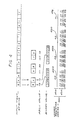
- an input string of data is represented in the first line of the Figure.
- the first letter, "N" by way of example, has an ASCII value of 7810, or 10011102. Its value is recorded herein as an optical signal of frequency F3 which is incident on the medium at an angle A2, together with optical signals of frequences F4, F3, and F2 which are incident on the medium at angle A1.
- the illustrated embodiment can represent the 128 characters of the ASCII character set using only two of the angle-of-incidence levels. Accordingly, coding algorithms of greater complexity can achieve greater data density.
- a series of registers 400 forming part of the encoder 14 are represented at the bottom of Figure 4.
- Each of the registers is associated with a respective combination of lower and higher order properties and/or levels (each of which is associated with integer values of successive orders of magnitude, so that each recordable combination of properties and levels has an associated combination of registers which store the appopriate digital values to control.
- the register 464 associated with F3 at angle A2 contains a value, such as digital "1", indicative of the "ON" state of that optical signal at that angle.
- registers 472, 474, 476 contains "ON"-indicative values, while the remaining registers contain values indicative of the "OFF" state.
- a binary storage bit can reside in two states, while each of the illustrated optical bits exists in 65,536 states, yielding a data representation system of base 65,536.
- the disclosed system may be used, of course, in conjunction with a recording signal of greater complexity. For example, additional properties such as intensity and polarization, and additional levels of angles-of-incidence and frequencies, and other added properties can all be used.
- the number of quanta per storage unit is limited only by the ability of the hardware and storage media to record and then distinguish light signals of the various multiplexed properties and levels.
- Storage capacity undergoes a rapid increase as the number of properties and levels are increased. For example, a system which utilizes 10 reference signal properties, each recordable at 10 levels, produces a reference signal having 1024-to-the-1,000,000,000th combinations (roughly one followed by three billion zeros). A single bit would therefore be capable of representing any digital number up to and including that magnitude. Note that 10 gigabits (10 billion binary bits) of binary digital memory would be required to store a comparable amount of information.
- disk 20 may use a reflective rather than a transmissive base layer, so that both sides of the disc can be used for data recording.
- Multiplexed logarithmic digitization might also be employed in single or multiple fibre-optical data transmission systems to substantially increas data transmission rates.
- Multiplexed central processing unit (CPU) registers may also be utilized to increase processing speed and representational power in main memory.
Landscapes
- Physics & Mathematics (AREA)
- General Physics & Mathematics (AREA)
- Optical Recording Or Reproduction (AREA)
- Holo Graphy (AREA)
- Optical Record Carriers And Manufacture Thereof (AREA)
Priority Applications (2)
| Application Number | Priority Date | Filing Date | Title |
|---|---|---|---|
| DE69025593T DE69025593T2 (de) | 1986-12-01 | 1990-04-10 | Datenaufzeichnung |
| AT90303876T ATE134786T1 (de) | 1986-12-01 | 1990-04-10 | Datenaufzeichnung |
Applications Claiming Priority (2)
| Application Number | Priority Date | Filing Date | Title |
|---|---|---|---|
| US93623786A | 1986-12-01 | 1986-12-01 | |
| US07/239,617 US4958338A (en) | 1986-12-01 | 1988-09-01 | Hierarchically multiplexed optical recording system for storage of digital data |
Publications (2)
| Publication Number | Publication Date |
|---|---|
| EP0451386A1 true EP0451386A1 (de) | 1991-10-16 |
| EP0451386B1 EP0451386B1 (de) | 1996-02-28 |
Family
ID=26932718
Family Applications (1)
| Application Number | Title | Priority Date | Filing Date |
|---|---|---|---|
| EP90303876A Expired - Lifetime EP0451386B1 (de) | 1986-12-01 | 1990-04-10 | Datenaufzeichnung |
Country Status (4)
| Country | Link |
|---|---|
| US (1) | US4958338A (de) |
| EP (1) | EP0451386B1 (de) |
| AT (1) | ATE134786T1 (de) |
| DE (1) | DE69025593T2 (de) |
Cited By (3)
| Publication number | Priority date | Publication date | Assignee | Title |
|---|---|---|---|---|
| FR2703815A1 (fr) * | 1993-04-06 | 1994-10-14 | Imagine Technologies | Support portatif d'informations à mémoire holographique multiplexée. |
| WO1995017748A1 (en) * | 1993-12-23 | 1995-06-29 | Tamarack Storage Devices | Holographic data storage system with disk based holographic storage media |
| US5481523A (en) * | 1993-12-23 | 1996-01-02 | Tamarack Storage Devices | Gantry for positioning a read/write head of a holographic information storage system |
Families Citing this family (7)
| Publication number | Priority date | Publication date | Assignee | Title |
|---|---|---|---|---|
| US4958338A (en) * | 1986-12-01 | 1990-09-18 | Miller William P | Hierarchically multiplexed optical recording system for storage of digital data |
| US5465243A (en) * | 1992-04-24 | 1995-11-07 | E-Systems, Inc. | Optical recorder and reader of data on light sensitive media |
| AU4105493A (en) * | 1992-05-01 | 1993-11-29 | E-Systems Incorporated | High data rate optical tape recorder |
| US6272095B1 (en) * | 1994-07-22 | 2001-08-07 | California Institute Of Technology | Apparatus and method for storing and/or reading data on an optical disk |
| US6396042B1 (en) | 1999-10-19 | 2002-05-28 | Raytheon Company | Digital laser image recorder including delay lines |
| FR2803424B1 (fr) * | 2000-01-04 | 2002-10-11 | France Telecom | Procede de photoinscription de donnees |
| JP4459721B2 (ja) * | 2004-06-01 | 2010-04-28 | アルプス電気株式会社 | ホログラム記録媒体及びその書込み方法 |
Citations (8)
| Publication number | Priority date | Publication date | Assignee | Title |
|---|---|---|---|---|
| US3626321A (en) * | 1968-11-13 | 1971-12-07 | Ibm | Optical scanner and method for optical scanning |
| US3635545A (en) * | 1967-04-14 | 1972-01-18 | Eastman Kodak Co | Multiple beam generation |
| US3704929A (en) * | 1969-12-06 | 1972-12-05 | Nippon Electric Co | Large capacity associative memory employing holography |
| DE2261143A1 (de) * | 1972-12-14 | 1974-06-20 | Agfa Gevaert Ag | Verfahren und vorrichtung zur aufzeichnung und wiedergabe von daten |
| US3874785A (en) * | 1972-06-02 | 1975-04-01 | Thomson Csf | Optical deflector arrangement for use in holographic data storage devices |
| US3987421A (en) * | 1973-12-18 | 1976-10-19 | Thomson-Csf | Halographic process for the real-time storage and retrieval of high speed digitally encoded information and an apparatus for implementing said process |
| EP0233984A1 (de) * | 1986-01-22 | 1987-09-02 | Hitachi, Ltd. | Verfahren zur Aufzeichnung und Wiedergabe digitaler Information und Gerät dafür |
| US4958338A (en) * | 1986-12-01 | 1990-09-18 | Miller William P | Hierarchically multiplexed optical recording system for storage of digital data |
Family Cites Families (9)
| Publication number | Priority date | Publication date | Assignee | Title |
|---|---|---|---|---|
| US3281151A (en) * | 1963-05-09 | 1966-10-25 | Kalart Co Inc | Method of and device for recording and reproducing photographic sound patterns |
| US3408656A (en) * | 1966-05-18 | 1968-10-29 | Eastman Kodak Co | Method and appartus for recording composite diffraction grating pattern |
| US3407405A (en) * | 1966-05-18 | 1968-10-22 | Eastman Kodak Co | Recorder for producing composite diffraction grating pattern |
| US4025731A (en) * | 1971-04-20 | 1977-05-24 | Thomson-Csf | Optical record, and associated recording and reading-out devices |
| US3946367A (en) * | 1972-12-20 | 1976-03-23 | Videonics Of Hawaii, Inc. | Three dimensional electro-optical retrieval system |
| US3969593A (en) * | 1974-11-08 | 1976-07-13 | The Association Of Motion Picture And Television Producers Inc. | Sound recording on color film by hue modulation |
| DE3170922D1 (en) * | 1980-04-22 | 1985-07-18 | Agfa Gevaert Nv | Recording material for storage of digital information and a recording method for storage of digital information |
| US4375096A (en) * | 1981-03-10 | 1983-02-22 | Rca Corporation | Multi-bandwidth optical playback apparatus with elongated read spot |
| US4544961A (en) * | 1983-09-01 | 1985-10-01 | Sperry Corporation | Triplex digital magnetic recording and reproducing system |
-
1988
- 1988-09-01 US US07/239,617 patent/US4958338A/en not_active Expired - Lifetime
-
1990
- 1990-04-10 AT AT90303876T patent/ATE134786T1/de active
- 1990-04-10 DE DE69025593T patent/DE69025593T2/de not_active Expired - Fee Related
- 1990-04-10 EP EP90303876A patent/EP0451386B1/de not_active Expired - Lifetime
Patent Citations (8)
| Publication number | Priority date | Publication date | Assignee | Title |
|---|---|---|---|---|
| US3635545A (en) * | 1967-04-14 | 1972-01-18 | Eastman Kodak Co | Multiple beam generation |
| US3626321A (en) * | 1968-11-13 | 1971-12-07 | Ibm | Optical scanner and method for optical scanning |
| US3704929A (en) * | 1969-12-06 | 1972-12-05 | Nippon Electric Co | Large capacity associative memory employing holography |
| US3874785A (en) * | 1972-06-02 | 1975-04-01 | Thomson Csf | Optical deflector arrangement for use in holographic data storage devices |
| DE2261143A1 (de) * | 1972-12-14 | 1974-06-20 | Agfa Gevaert Ag | Verfahren und vorrichtung zur aufzeichnung und wiedergabe von daten |
| US3987421A (en) * | 1973-12-18 | 1976-10-19 | Thomson-Csf | Halographic process for the real-time storage and retrieval of high speed digitally encoded information and an apparatus for implementing said process |
| EP0233984A1 (de) * | 1986-01-22 | 1987-09-02 | Hitachi, Ltd. | Verfahren zur Aufzeichnung und Wiedergabe digitaler Information und Gerät dafür |
| US4958338A (en) * | 1986-12-01 | 1990-09-18 | Miller William P | Hierarchically multiplexed optical recording system for storage of digital data |
Non-Patent Citations (3)
| Title |
|---|
| APPLIED OPTICS, vol. 2, no. 4, April 1963, NEW YORK, US; pages 393 - 399; P.J.van HEERDEN: "THEORY OF OPTICAL INFORMATION STORAGE IN SOLIDS" * |
| IEEE TRANSACTIONS ON MAGNETICS, vol. MAG-9, no. 2, June 1973, NEW YORK, US; pages 83 - 94; L.D'AURIA ET AL.: "HOLOGRAPHIC READ-WRITE MEMORY AND CAPACITY ENHANCEMENT BY 3-D STORAGE" * |
| RUNDFUNKTECHNISCHE MITTEILUNGEN, vol. 21, no. 5, October 1977, NORDERSTEDT, DE; pages 231 - 232; M.ROTTHALER: "HOLOGRAPHISCHE AUFZEICHNUNG VON FERNSEHINFORMATION" * |
Cited By (4)
| Publication number | Priority date | Publication date | Assignee | Title |
|---|---|---|---|---|
| FR2703815A1 (fr) * | 1993-04-06 | 1994-10-14 | Imagine Technologies | Support portatif d'informations à mémoire holographique multiplexée. |
| WO1995017748A1 (en) * | 1993-12-23 | 1995-06-29 | Tamarack Storage Devices | Holographic data storage system with disk based holographic storage media |
| US5481523A (en) * | 1993-12-23 | 1996-01-02 | Tamarack Storage Devices | Gantry for positioning a read/write head of a holographic information storage system |
| US5566387A (en) * | 1993-12-23 | 1996-10-15 | Tamarack Storage Devices | Diamond shaped holographic storage regions oriented along a common radial column line for higher storage density |
Also Published As
| Publication number | Publication date |
|---|---|
| ATE134786T1 (de) | 1996-03-15 |
| EP0451386B1 (de) | 1996-02-28 |
| DE69025593T2 (de) | 1996-10-24 |
| US4958338A (en) | 1990-09-18 |
| DE69025593D1 (de) | 1996-04-04 |
Similar Documents
| Publication | Publication Date | Title |
|---|---|---|
| US4958338A (en) | Hierarchically multiplexed optical recording system for storage of digital data | |
| US6154432A (en) | Optical storage system | |
| US4691299A (en) | Method and apparatus for reusing non-erasable memory media | |
| EP0405926A3 (en) | Transferring data in a digital data processing system | |
| US6661725B2 (en) | Apparatus for storing/restoring holographic data and method for coding/decoding holographic data | |
| Pansatiankul et al. | Multidimensional modulation codes and error correction for page-oriented optical data storage | |
| US5479164A (en) | Photonic data compression system and method | |
| GB1343153A (en) | Information handling apparatus | |
| Talyansky et al. | Efficient code constructions for certain two-dimensional constraints | |
| EP0449121B1 (de) | Optisches Aufzeichnungsmedium und Aufzeichnungs-/Wiedergabemethode dafür | |
| US3573766A (en) | Apparatus and process for recording binary data in compact form | |
| US5038335A (en) | Hierarchically multiplexed optical recording system for storage of digital data | |
| US3704929A (en) | Large capacity associative memory employing holography | |
| KR100355998B1 (ko) | 홀로그래픽 디지털 저장 및 재생 시스템과 데이터코딩/디코딩 방법 | |
| KR910001725A (ko) | 기록장치와 재생장치 | |
| US3737878A (en) | Holographic read/write storage system | |
| US4802154A (en) | High density codes for optical recording | |
| JPS62145573A (ja) | 情報再生装置 | |
| KR960002329A (ko) | 영상노래반주용의 기록매체, 이의 기록 및 재생방법 그리고 이에 적합한 재생장치 | |
| KR100551367B1 (ko) | 홀로그래픽 데이터 엔코딩/디코딩 방법 | |
| Sakaguchi et al. | The hologram tablet: a new graphic input device | |
| KR100551372B1 (ko) | 홀로그래픽 디지털 데이터 시스템의 코딩 및 디코딩 방법 | |
| KR100551373B1 (ko) | 홀로그래픽 디지털 데이터 시스템의 코딩 및 디코딩 방법 | |
| Morozov | Associative parallel-search memory | |
| KR100475235B1 (ko) | 홀로그래픽 디지털 데이타 저장 시스템의 코딩 및 디코딩장치와 이에 관련된 코딩 및 디코딩 방법 |
Legal Events
| Date | Code | Title | Description |
|---|---|---|---|
| PUAI | Public reference made under article 153(3) epc to a published international application that has entered the european phase |
Free format text: ORIGINAL CODE: 0009012 |
|
| AK | Designated contracting states |
Kind code of ref document: A1 Designated state(s): AT BE CH DE DK ES FR GB GR IT LI LU NL SE |
|
| 17P | Request for examination filed |
Effective date: 19920408 |
|
| 17Q | First examination report despatched |
Effective date: 19941130 |
|
| GRAH | Despatch of communication of intention to grant a patent |
Free format text: ORIGINAL CODE: EPIDOS IGRA |
|
| GRAA | (expected) grant |
Free format text: ORIGINAL CODE: 0009210 |
|
| AK | Designated contracting states |
Kind code of ref document: B1 Designated state(s): AT BE CH DE DK ES FR GB GR IT LI LU NL SE |
|
| PG25 | Lapsed in a contracting state [announced via postgrant information from national office to epo] |
Ref country code: IT Free format text: LAPSE BECAUSE OF FAILURE TO SUBMIT A TRANSLATION OF THE DESCRIPTION OR TO PAY THE FEE WITHIN THE PRESCRIBED TIME-LIMIT;WARNING: LAPSES OF ITALIAN PATENTS WITH EFFECTIVE DATE BEFORE 2007 MAY HAVE OCCURRED AT ANY TIME BEFORE 2007. THE CORRECT EFFECTIVE DATE MAY BE DIFFERENT FROM THE ONE RECORDED. Effective date: 19960228 Ref country code: NL Free format text: LAPSE BECAUSE OF FAILURE TO SUBMIT A TRANSLATION OF THE DESCRIPTION OR TO PAY THE FEE WITHIN THE PRESCRIBED TIME-LIMIT Effective date: 19960228 Ref country code: AT Effective date: 19960228 Ref country code: CH Free format text: LAPSE BECAUSE OF FAILURE TO SUBMIT A TRANSLATION OF THE DESCRIPTION OR TO PAY THE FEE WITHIN THE PRESCRIBED TIME-LIMIT Effective date: 19960228 Ref country code: BE Effective date: 19960228 Ref country code: ES Free format text: THE PATENT HAS BEEN ANNULLED BY A DECISION OF A NATIONAL AUTHORITY Effective date: 19960228 Ref country code: DK Effective date: 19960228 Ref country code: LI Free format text: LAPSE BECAUSE OF FAILURE TO SUBMIT A TRANSLATION OF THE DESCRIPTION OR TO PAY THE FEE WITHIN THE PRESCRIBED TIME-LIMIT Effective date: 19960228 Ref country code: GR Free format text: LAPSE BECAUSE OF FAILURE TO SUBMIT A TRANSLATION OF THE DESCRIPTION OR TO PAY THE FEE WITHIN THE PRESCRIBED TIME-LIMIT Effective date: 19960228 |
|
| REF | Corresponds to: |
Ref document number: 134786 Country of ref document: AT Date of ref document: 19960315 Kind code of ref document: T |
|
| REF | Corresponds to: |
Ref document number: 69025593 Country of ref document: DE Date of ref document: 19960404 |
|
| PG25 | Lapsed in a contracting state [announced via postgrant information from national office to epo] |
Ref country code: LU Free format text: LAPSE BECAUSE OF NON-PAYMENT OF DUE FEES Effective date: 19960430 |
|
| ET | Fr: translation filed | ||
| PG25 | Lapsed in a contracting state [announced via postgrant information from national office to epo] |
Ref country code: SE Effective date: 19960531 |
|
| NLV1 | Nl: lapsed or annulled due to failure to fulfill the requirements of art. 29p and 29m of the patents act | ||
| REG | Reference to a national code |
Ref country code: CH Ref legal event code: PL |
|
| PLBE | No opposition filed within time limit |
Free format text: ORIGINAL CODE: 0009261 |
|
| STAA | Information on the status of an ep patent application or granted ep patent |
Free format text: STATUS: NO OPPOSITION FILED WITHIN TIME LIMIT |
|
| 26N | No opposition filed | ||
| PGFP | Annual fee paid to national office [announced via postgrant information from national office to epo] |
Ref country code: GB Payment date: 19990409 Year of fee payment: 10 |
|
| PGFP | Annual fee paid to national office [announced via postgrant information from national office to epo] |
Ref country code: FR Payment date: 19990420 Year of fee payment: 10 |
|
| PGFP | Annual fee paid to national office [announced via postgrant information from national office to epo] |
Ref country code: DE Payment date: 19990426 Year of fee payment: 10 |
|
| PG25 | Lapsed in a contracting state [announced via postgrant information from national office to epo] |
Ref country code: GB Free format text: LAPSE BECAUSE OF NON-PAYMENT OF DUE FEES Effective date: 20000410 |
|
| GBPC | Gb: european patent ceased through non-payment of renewal fee |
Effective date: 20000410 |
|
| PG25 | Lapsed in a contracting state [announced via postgrant information from national office to epo] |
Ref country code: FR Free format text: LAPSE BECAUSE OF NON-PAYMENT OF DUE FEES Effective date: 20001229 |
|
| PG25 | Lapsed in a contracting state [announced via postgrant information from national office to epo] |
Ref country code: DE Free format text: LAPSE BECAUSE OF NON-PAYMENT OF DUE FEES Effective date: 20010201 |
|
| REG | Reference to a national code |
Ref country code: FR Ref legal event code: ST |