EP0451388A1 - Selbstschliessendes Ventil - Google Patents
Selbstschliessendes Ventil Download PDFInfo
- Publication number
- EP0451388A1 EP0451388A1 EP90303900A EP90303900A EP0451388A1 EP 0451388 A1 EP0451388 A1 EP 0451388A1 EP 90303900 A EP90303900 A EP 90303900A EP 90303900 A EP90303900 A EP 90303900A EP 0451388 A1 EP0451388 A1 EP 0451388A1
- Authority
- EP
- European Patent Office
- Prior art keywords
- valve
- container
- sealing body
- seating face
- fitting
- Prior art date
- Legal status (The legal status is an assumption and is not a legal conclusion. Google has not performed a legal analysis and makes no representation as to the accuracy of the status listed.)
- Withdrawn
Links
- 238000007789 sealing Methods 0.000 claims abstract description 38
- 239000004009 herbicide Substances 0.000 description 15
- 230000002363 herbicidal effect Effects 0.000 description 14
- 238000003780 insertion Methods 0.000 description 6
- 230000037431 insertion Effects 0.000 description 6
- 239000000463 material Substances 0.000 description 5
- 229920003023 plastic Polymers 0.000 description 4
- 239000004033 plastic Substances 0.000 description 4
- 238000000465 moulding Methods 0.000 description 3
- 230000000717 retained effect Effects 0.000 description 2
- 238000009987 spinning Methods 0.000 description 2
- 238000003466 welding Methods 0.000 description 2
- 239000002390 adhesive tape Substances 0.000 description 1
- 238000004891 communication Methods 0.000 description 1
- 230000000295 complement effect Effects 0.000 description 1
- 230000000694 effects Effects 0.000 description 1
- 238000010348 incorporation Methods 0.000 description 1
- 239000012528 membrane Substances 0.000 description 1
- 238000005192 partition Methods 0.000 description 1
- 230000007704 transition Effects 0.000 description 1
Images


Classifications
-
- B—PERFORMING OPERATIONS; TRANSPORTING
- B67—OPENING, CLOSING OR CLEANING BOTTLES, JARS OR SIMILAR CONTAINERS; LIQUID HANDLING
- B67D—DISPENSING, DELIVERING OR TRANSFERRING LIQUIDS, NOT OTHERWISE PROVIDED FOR
- B67D7/00—Apparatus or devices for transferring liquids from bulk storage containers or reservoirs into vehicles or into portable containers, e.g. for retail sale purposes
- B67D7/02—Apparatus or devices for transferring liquids from bulk storage containers or reservoirs into vehicles or into portable containers, e.g. for retail sale purposes for transferring liquids other than fuel or lubricants
- B67D7/0288—Container connection means
- B67D7/0294—Combined with valves
-
- B—PERFORMING OPERATIONS; TRANSPORTING
- B05—SPRAYING OR ATOMISING IN GENERAL; APPLYING FLUENT MATERIALS TO SURFACES, IN GENERAL
- B05B—SPRAYING APPARATUS; ATOMISING APPARATUS; NOZZLES
- B05B9/00—Spraying apparatus for discharge of liquids or other fluent material, without essentially mixing with gas or vapour
- B05B9/03—Spraying apparatus for discharge of liquids or other fluent material, without essentially mixing with gas or vapour characterised by means for supplying liquid or other fluent material
- B05B9/04—Spraying apparatus for discharge of liquids or other fluent material, without essentially mixing with gas or vapour characterised by means for supplying liquid or other fluent material with pressurised or compressible container; with pump
- B05B9/08—Apparatus to be carried on or by a person, e.g. of knapsack type
Definitions
- This invention relates to self-closing valves, and particularly, although not exclusively, to self-closing valves for incorporation into the outlet of a container for potentially harmful materials such as herbicides.
- EP-A-0300762 discloses a herbicide applicator which is adapted to receive a container of herbicide in a plug-in manner.
- the container has an outlet which engages a fitting situated within a handset of the applicator. With this system, care has to be taken when removing the container from the handset, to avoid spillage from the container of any herbicide remaining in it.
- Self-closing valves which comprise an outer annulus defining a seating face sealing body which is displaceable relatively to the annulus to open and close the valve.
- the sealing body is biased towards the seating face by a spring.
- the known valves are assembled from several components, and are relatively expensive to produce.
- valves are commonly used on containers which can be releasably fitted to further equipment which utilises the contents of the containers.
- the fitting of the container to the equipment causes automatic opening of the valve.
- the known valves have little resistance to being opened by children.
- the sealing body is supported with respect to the annulus by a flexible strap which biases the sealing body into sealing contact with the seating face.
- the strap is formed integrally with the valve member, for example by moulding.
- the valve may comprise two components, both made from plastics material, one of which comprises the sealing body and the strap, and the other of which comprises the annulus defining the seating face.
- the strap may be flexed through 180°, and terminate at inner and outer cylindrical portions.
- the sealing body preferably has an actuating pin which extends through the valve seat.
- the actuating pin may have a conical end.
- the outer annulus may have an annular recess for receiving a cylindrical projection of a fitting to which the valve can be releasably coupled.
- the fitting may have an abutment for operative engagement with the sealing body so as to open the valve when the fitting is coupled to the valve.
- the valve may be fitted to the outlet of a container.
- the container may have a cylindrical boss defining a shoulder against which the valve locates.
- Figure 1 shows a herbicide applicator having a handset 2 and a delivery head 4 which is connected to the handset 2 by a support tube 6.
- the delivery head 4 accommodates an electric motor (not shown) which drives a spinning disc 8.
- the handset 2 receives a container 10 of herbicide, and also accommodates one or more batteries (not shown).
- a supply duct and electrical leads extend along the support tube 6 to supply herbicide and electrical power to the delivery head 4.
- a control valve 12 ( Figure 2) is provided in the handset 2 for controlling the flow of herbicide from the container 10 to the delivery head 4.
- the valve 12 is operated by means of a trigger 14 on the handset.
- the trigger 14 also controls an electrical switch (not shown) for controlling the supply of electrical current to the motor in the delivery head 4.
- the applicator is carried by a walking operator, in order to dispense herbicide over plants, or areas of ground, to be treated.
- operation of the trigger 14 opens the valve 12, allowing the herbicide to flow from the container 10 to the spinning disc.
- Operation of the trigger 14 also actuates a switch (not shown) in the handset, so that electric current flows to the motor in the head 4, which rotates the disc 8. The herbicide is thus discharged from the disc 8 in the form of droplets.
- the handset 2 and the container 10 are shown in greater detail in Figures 2 and 3. It will be appreciated from Figures 2 and 3 that the trigger 14 is provided at one end of an operating lever 16 which is pivotally connected to the body of the handset for movement about a pivot axis 18.
- a cranked operating rod 20 is connected at one end 22 to the lever 16 and at the other end 24 to an operating stem 26 of the valve 12.
- a slide 28 is provided for retaining the trigger 14 in an operating position.
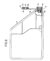
- the handset 2 has a recess 30 for receiving a leading end of the container 10.
- a latching member 32 is pivotally connected to the handset 2 and has a cam portion 34 and a detent portion 36. As the container 10 is inserted into the recess 30, a leading face of the container 10 engages the cam portion 34, causing the latching member 32 to pivot upwardly, as viewed in Figure 2, to bring the detent portion 36 into engagement with a recess 38 in the container.
- the latched position is shown in Figure 3.
- the valve 12 has an inlet spigot 40 which projects into the recess 30.
- the container 10 has an outlet fitting 42 which, when the container 10 is latched within the recess 30, engages the inlet spigot 40.
- FIG. 4 shows the valve 12 in the condition corresponding to Figure 2, while Figure 5 shows the valve 12 and the outlet fitting 42 in the condition corresponding to Figure 3.
- the valve 12 comprises a valve body 44 having an outlet 46.
- a valve seat 48 which, in the condition shown in Figure 4, is engaged by a valve head 50 of a valve closure element 52, which thus, prevents communication between the inlet spigot 40 and the outlet 46.
- the valve head 50 is maintained against the valve seat 48 by a spring 54.
- the closure element 52 is a one-piece moulded component, for example of plastics material, comprising both the valve head 50 and the operating stem 26.
- the operating stem 26 extends from the valve head 50 through the valve seat 48 and through a guide passage 56 formed in a collar 58 which is set into a bore 60 in the valve body 44.
- a sealing ring 62 is provided between the operating stem 26 and the bore 56.
- a further sealing ring 64 is provided to ensure a reliable seal between the valve head 50 and the seat 48, when the valve is closed.
- the valve body 44 has an insertion aperture 66.
- This insertion aperture 66 is partially closed by a plug 68, in which an inlet passage 70 is formed.
- the plug 68 is retained within the insertion aperture 66 by the spigot 40, which is welded, or otherwise secured, to the valve body 44.
- the spigot 40 is provided with a bulkhead mounting 72, by which the valve 12 is secured within the handset 2.
- a further partition 74 engages the outlet 46 to ensure a firm location for the valve 12.
- An abutment 76 is supported within the spigot 40 by radial webs 78. At its end facing away from the valve 12, the abutment 76 has a conical recess 80.
- the valve body 44 can be produced from plastics material by a moulding operation in a relatively simple manner.
- the insertion aperture and the part of the interior of the valve body 44 which accommodates the valve head 50 can be formed by means of a first core
- the interior of the outlet 46 can be formed by means of a second core
- the bore 60 and the circumferential wall of the valve seat 48 can be formed by means of a third core.
- the outlet fitting 42 of the container 10 is shown in greater detail in Figure 6.
- the fitting 42 comprises a seat element 82 and a valve element 84, both of which are made from plastics material.
- the seat element 82 comprises inner and outer walls 86, 88 respectively which defines between them an annular recess 90.
- the inner and outer walls 86, 88 are connected together at one end by an annular web 92.
- This annular web 92 projects inwards beyond the inner wall 86 and terminates at a frusto conical seating face 94.
- the seal element 82 has an outwardly projecting flange 124.
- a cap 96 ( Figures 7 to 10) is moulded integrally with the seat element 82, and is connected to the flange 124 by a strap 98.
- the valve element 84 comprises a sealing body 100 which has a frusto conical sealing face 102 and a projecting pin 104.
- a frusto conical transitional region 103 is provided between the sealing face 102 and the pin 104.
- the pin 104 terminates at a conical surface 106 which is complementary to the conical recess 80 at the end of the abutment 76.
- the sealing body 100 is surrounded by a skirt 108 which is connected to the sealing body 100 by a cylindrical portion 112 and by five flexible straps 116, which are flexed through an angle of 180°.
- the fitting 42 is received in a boss 118 formed on the end of the container 10.
- the boss 118 terminates at a shoulder 120 against which abuts the transition between the skirt 108 and the cylindrical portion 112.
- the outer wall 88 of the seat element 82 is received within the skirt 108, and the seat element 82 is secured within the boss 118, for example by welding.
- the seating face 94 of the seat element 82 engages the sealing face 102 of the sealing body 100, and deflects the sealing body 100 slightly to the left relatively to the unstressed configuration of the valve element 84.
- the sealing body 100 is biassed into contact with the seating face 94 by the resilience of the flexible straps 116. Consequently, the fitting 42 normally prevents outflow of the contents of the container 10.
- insertion of the container 10 into the recess 30 in the handset 2 results in contact between the conical surface 106 of the pin 104 and the conical recess 80 of the abutment 76.
- the cap 96 comprises an outer skirt 122 for engagement over a flange 124 of the seat element 82, an intermediate skirt 126 for engagement in the annular recess 90, and an inner skirt 128 for engagement with the inner surface of the inner wall 86. Consequently, when the cap is fitted, as shown in Figure 7, secure sealing engagement with the fitting 42 is made.
- the outer skirt 122 is provided with two oppositely disposed barbs 143.
- the flange 124 of the seating element 82 has two corresponding oppositely disposed notches 132.
- the barbs 130 and the notches 132 do not coincide respectively with one another when the cap is placed over the fitting 42 in a manner which creates least torsional stress in the strap 98 about the axis of the fitting 42. Nevertheless, in this position of lease torsional stress, the cap can be snapped over the fitting 42, with the barbs 130 engaging the flange 124.
- the barbs 130 engage the flange 124 sufficiently firmly in this position to prevent removal of the cap from the fitting 42.
- To remove the cap 96 it must first be rotated relatively to the container 10 in the direction of the arrow A in Figure 9 until the barbs 130 coincide with the notches 132. Even in this position, the barbs 130 still engage beneath the flange 124, but the reduced extent of the flange 124 at the notches 132 makes it possible to disengage the barbs 130, one at a time, by pulling outwardly on lugs 134 on the cap 96.
- Containers 10 of herbicide for use with the applicator shown in Figure 1 will be supplied with the cap 96 fitted, and possibly retained in place by some auxiliary means, such as adhesive tape. The operator then removes the cap by rotating it in the direction A as shown in Figure 9 until the barbs 130 are aligned with the notches 132, and then pulls off the cap by tugging on one or other of the lugs 134. Even though the cap is removed, flow from the container 10 is still prevented by the valve provided in the fitting 42.
- the container With the cap 96 removed, the container is inserted into the recess 30 in the handset, as shown in Figure 2. This causes the end of the spigot 40 to enter the annular recess 90, so creating a seal between the fitting 42 and the spigot 40. After the creation of this seal, the abutment 76 is engaged by the pin 104, and subsequent movement of the container 10 to the fully engaged position in the handset 2 causes the sealing body 100 to be displaced from the seating face 94, permitting flow from the container 10 through the spigot 40 to the valve 12.
- the cap When the container 10 is inserted into the recess 30, the cap is accommodated within a clearance provided between the front face of the container 10 and an adjacent wall of the recess 30, as shown in Figure 3.
- the operator depresses the trigger 14, so energising the motor in the delivery head 4 and, via the lever 16 and the operating rod 20, opening the valve 12. Flow of herbicide then takes place through the valve 12 to the outlet 46, and thence, through the supply duct in the support tube 6, to the distribution head 4.
- the container 10 When a treatment operation is completed and the trigger 14 released to close the valve 12, the container 10 is ejected from the handset 2 by lowering the latching member 32 to the position shown in Figure 2. The resulting movement of the cam 34 pushes the container 10 away from the valve 12, so disengaging the pin 104 from the abutment 76, and finally disengaging the spigot 40 from the annular recess 90.
- the sealing body 100 is returned, under the resilient forces applied by the flexible membrane 110, into sealing engagement with the seating face 94, so preventing further flow from the container 10. Added safety is then achieved by refitting the cap 96 by merely snapping it over the flange 124.
Landscapes
- Engineering & Computer Science (AREA)
- Mechanical Engineering (AREA)
- Closures For Containers (AREA)
Priority Applications (4)
| Application Number | Priority Date | Filing Date | Title |
|---|---|---|---|
| EP90303900A EP0451388A1 (de) | 1990-04-11 | 1990-04-11 | Selbstschliessendes Ventil |
| AU73882/91A AU7388291A (en) | 1990-04-11 | 1991-03-28 | Self-closing valves |
| CA002039367A CA2039367A1 (en) | 1990-04-11 | 1991-03-28 | Self-closing valves |
| ZA912496A ZA912496B (en) | 1990-04-11 | 1991-04-04 | Self-closing valves |
Applications Claiming Priority (1)
| Application Number | Priority Date | Filing Date | Title |
|---|---|---|---|
| EP90303900A EP0451388A1 (de) | 1990-04-11 | 1990-04-11 | Selbstschliessendes Ventil |
Publications (1)
| Publication Number | Publication Date |
|---|---|
| EP0451388A1 true EP0451388A1 (de) | 1991-10-16 |
Family
ID=8205371
Family Applications (1)
| Application Number | Title | Priority Date | Filing Date |
|---|---|---|---|
| EP90303900A Withdrawn EP0451388A1 (de) | 1990-04-11 | 1990-04-11 | Selbstschliessendes Ventil |
Country Status (4)
| Country | Link |
|---|---|
| EP (1) | EP0451388A1 (de) |
| AU (1) | AU7388291A (de) |
| CA (1) | CA2039367A1 (de) |
| ZA (1) | ZA912496B (de) |
Cited By (3)
| Publication number | Priority date | Publication date | Assignee | Title |
|---|---|---|---|---|
| WO1995024972A1 (en) * | 1994-03-07 | 1995-09-21 | Itsac N.V. Trading As Innovative Packaging | Liquid dispenser with refill packing |
| US6039301A (en) * | 1997-04-22 | 2000-03-21 | U.S. Philips Corporation | Container and sealing device for use in the container |
| WO2007128739A3 (en) * | 2006-05-02 | 2008-04-10 | Akzo Nobel Coatings Int Bv | Process and paint spray device |
Families Citing this family (1)
| Publication number | Priority date | Publication date | Assignee | Title |
|---|---|---|---|---|
| EP0487799A1 (de) * | 1990-11-29 | 1992-06-03 | Nomix-Chipman Limited | Behälter für Flüssigkeiten |
Citations (5)
| Publication number | Priority date | Publication date | Assignee | Title |
|---|---|---|---|---|
| GB615258A (en) * | 1943-01-12 | 1949-01-04 | Jean Emile Lucien Leperre | Methods and means for casking and drawing-off beer and like liquids in a sterilized manner and protecting said liquids from air |
| US2601339A (en) * | 1948-03-01 | 1952-06-24 | Thompson Prod Inc | Drum cap and spigot valve assembly |
| US3687161A (en) * | 1970-06-01 | 1972-08-29 | Hansen Mfg | Quick connect valve coupling |
| EP0270302A1 (de) * | 1986-11-27 | 1988-06-08 | Unilever Plc | Schlauchkupplung |
| US4802513A (en) * | 1981-05-07 | 1989-02-07 | Ciba-Geigy Corporation | Closed system chemical container |
-
1990
- 1990-04-11 EP EP90303900A patent/EP0451388A1/de not_active Withdrawn
-
1991
- 1991-03-28 CA CA002039367A patent/CA2039367A1/en not_active Abandoned
- 1991-03-28 AU AU73882/91A patent/AU7388291A/en not_active Abandoned
- 1991-04-04 ZA ZA912496A patent/ZA912496B/xx unknown
Patent Citations (5)
| Publication number | Priority date | Publication date | Assignee | Title |
|---|---|---|---|---|
| GB615258A (en) * | 1943-01-12 | 1949-01-04 | Jean Emile Lucien Leperre | Methods and means for casking and drawing-off beer and like liquids in a sterilized manner and protecting said liquids from air |
| US2601339A (en) * | 1948-03-01 | 1952-06-24 | Thompson Prod Inc | Drum cap and spigot valve assembly |
| US3687161A (en) * | 1970-06-01 | 1972-08-29 | Hansen Mfg | Quick connect valve coupling |
| US4802513A (en) * | 1981-05-07 | 1989-02-07 | Ciba-Geigy Corporation | Closed system chemical container |
| EP0270302A1 (de) * | 1986-11-27 | 1988-06-08 | Unilever Plc | Schlauchkupplung |
Cited By (6)
| Publication number | Priority date | Publication date | Assignee | Title |
|---|---|---|---|---|
| WO1995024972A1 (en) * | 1994-03-07 | 1995-09-21 | Itsac N.V. Trading As Innovative Packaging | Liquid dispenser with refill packing |
| NL9400346A (nl) * | 1994-03-07 | 1995-10-02 | Itsac Nv | Vloeistofdispenser met navulverpakking. |
| AU694186B2 (en) * | 1994-03-07 | 1998-07-16 | Itsac N.V. Trading As Innovative Packaging N.V. | Liquid dispenser with refill packing |
| CN1072528C (zh) * | 1994-03-07 | 2001-10-10 | 革新包装依萨克N.V. | 带包装袋的液体分配器、接头系统和用于分配器的包装袋 |
| US6039301A (en) * | 1997-04-22 | 2000-03-21 | U.S. Philips Corporation | Container and sealing device for use in the container |
| WO2007128739A3 (en) * | 2006-05-02 | 2008-04-10 | Akzo Nobel Coatings Int Bv | Process and paint spray device |
Also Published As
| Publication number | Publication date |
|---|---|
| CA2039367A1 (en) | 1991-10-12 |
| AU7388291A (en) | 1991-10-24 |
| ZA912496B (en) | 1992-01-29 |
Similar Documents
| Publication | Publication Date | Title |
|---|---|---|
| JP4322422B2 (ja) | スプレーヘッド | |
| JPH03226497A (ja) | 蒸気回収ノズル及びそのためのサブアセンブリ | |
| US4324351A (en) | Locking actuator for a dispenser | |
| US5337775A (en) | Dispensing taps | |
| JP4354116B2 (ja) | 空気通路内臓タップ | |
| CA2473899C (en) | Intermittent aerosol dispensing valve | |
| KR0150628B1 (ko) | 압력 밥솥 잠금 장치 | |
| US6415827B1 (en) | Filler neck closure assembly | |
| EP1991475B1 (de) | Aerosoldosenventil und abdeckungsanordnung | |
| PT808287E (pt) | Montagem de cobertura de pulverizador | |
| WO1981003648A1 (en) | Finger-actuated slideable dispensing valve | |
| US20030106901A1 (en) | Spray dispensing device with nozzle closure | |
| US6106503A (en) | Catheter valve | |
| BRPI0610525A2 (pt) | sistema de válvula aerossol de auto-purga | |
| CA2639994C (en) | Connection subassembly for connecting a supply container to a target container | |
| US8028729B2 (en) | Connecting subassembly for connecting an initial container and a target container | |
| EP0675072A1 (de) | Ventileinrichtung und Anwendung derselben | |
| US6648186B2 (en) | Push-button faucet | |
| EP0658484B1 (de) | Kraftstofftank-Verschluss | |
| EP0978405B1 (de) | Kraftstoffbehältersystem | |
| US4324242A (en) | Feminine syringe | |
| WO1989007540A1 (en) | Hydraulic cylinder assembly | |
| EP0451391A1 (de) | Verschluss | |
| US20050061014A1 (en) | Extension for top of refrigerant can for dispensing without a valve | |
| EP0011929A1 (de) | Toilette |
Legal Events
| Date | Code | Title | Description |
|---|---|---|---|
| PUAI | Public reference made under article 153(3) epc to a published international application that has entered the european phase |
Free format text: ORIGINAL CODE: 0009012 |
|
| AK | Designated contracting states |
Kind code of ref document: A1 Designated state(s): AT BE CH DE DK ES FR GB GR IT LI LU NL SE |
|
| STAA | Information on the status of an ep patent application or granted ep patent |
Free format text: STATUS: THE APPLICATION IS DEEMED TO BE WITHDRAWN |
|
| 18D | Application deemed to be withdrawn |
Effective date: 19920417 |