EP0451399A2 - Coussin isolateur de vibrations pour suspensions de voitures ferroviaires - Google Patents
Coussin isolateur de vibrations pour suspensions de voitures ferroviaires Download PDFInfo
- Publication number
- EP0451399A2 EP0451399A2 EP90309721A EP90309721A EP0451399A2 EP 0451399 A2 EP0451399 A2 EP 0451399A2 EP 90309721 A EP90309721 A EP 90309721A EP 90309721 A EP90309721 A EP 90309721A EP 0451399 A2 EP0451399 A2 EP 0451399A2
- Authority
- EP
- European Patent Office
- Prior art keywords
- pad
- isolator
- sidewall portions
- bearing
- pads
- Prior art date
- Legal status (The legal status is an assumption and is not a legal conclusion. Google has not performed a legal analysis and makes no representation as to the accuracy of the status listed.)
- Withdrawn
Links
Images



Classifications
-
- B—PERFORMING OPERATIONS; TRANSPORTING
- B61—RAILWAYS
- B61F—RAIL VEHICLE SUSPENSIONS, e.g. UNDERFRAMES, BOGIES OR ARRANGEMENTS OF WHEEL AXLES; RAIL VEHICLES FOR USE ON TRACKS OF DIFFERENT WIDTH; PREVENTING DERAILING OF RAIL VEHICLES; WHEEL GUARDS, OBSTRUCTION REMOVERS OR THE LIKE FOR RAIL VEHICLES
- B61F5/00—Constructional details of bogies; Connections between bogies and vehicle underframes; Arrangements or devices for adjusting or allowing self-adjustment of wheel axles or bogies when rounding curves
- B61F5/26—Mounting or securing axle-boxes in vehicle or bogie underframes
- B61F5/30—Axle-boxes mounted for movement under spring control in vehicle or bogie underframes
- B61F5/305—Axle-boxes mounted for movement under spring control in vehicle or bogie underframes incorporating rubber springs
Definitions
- This invention relates generally to railroad car suspension systems, and more particularly relates to a novel isolator pad placed between each of the railroad car axle roller bearing adaptors and the car truck sideframes, which effectively decrease the unsprung mass of the car and make it possible to increase the payload of the car without causing an increase in damage to rails and roadbed.
- Intermodal wellcars for carrying containers have in the past used 100 ton trucks having 36" wheels. Each such car has a total load capacity of 131,500 lbs. which when reduced by the weight of the car itself provides carrying capacity for containers of approximately 100,000 lbs.
- Containers are usually on the order of 45 feet long and are carried with one container in the well and the second container stacked above it. The containers, on average, weigh between 50,000 and 60,000 lbs. each. Accordingly, in order to double stack containers, even 50,000 lb. containers constitute a marginal load when double stacked in a wellcar, and it is not possible to stack two 60,000 or a 50,000 and a 60,000 lb. container in a wellcar without overloading the trucks.
- a truck which is designated as a 125 ton truck and has 36" wheels.
- a wellcar using a pair of trucks of this type has a load carrying capacity of 157,500 lbs. which when reduced by the weight of car itself leaves a load carrying capability of approximately 125,000 lbs. This allows for double stacking of perhaps 99% of all containers in use today.
- the problem with the 125 ton trucks is that the railroads have not wanted to use them because they produce excessive track and roadbed damage as compared to the 100 ton truck.
- the load carrying capability of the wellcar can be materially increased without producing the adverse effects on the rail, and roadbed, and accordingly would be acceptable by the railroad industry.
- Jones' device consists of a resilient pad sandwiched between and bonded to an upper steel plate and a lower steel plate, the resilient pad being specified as "rubber or synthetic rubber or any suitable plastic material". Rubber and synthetic rubber can not be so used because in use they are extruded outward from between the steel plates and quickly become ineffective. It is known that Jones type pads utilizing rubber have been tried in the past, in 100 ton truck cars, and have failed after very short use with cars which were substantially under loaded. The use of such devices was abandoned by the railroads before the advent of the intermodal double stack wellcars.
- a vertical isolator pad was developed of the type to be subsequently described in connection with Figure 3, consisting of an elastomer pad having steel facing sheets or plates bonded to the upper and lower surfaces. The pad was located between the roller bearing adaptor and sideframe, with its lower and upper pad plates located in pockets in the bearing adaptor and sideframe.
- the face plates were considered by the railroads to be essential to prevent wear of the pad by providing metal-to-metal contact between the pad and the adaptor and sideframe.
- These isolator pads were extensively tested at the American Association of Rails Transportation Test Center in Pueblo, Colorado with instrumented track and instrumented wheel sets on several different kinds of track situations. The results of these tests were presented in a paper entitled "A Primary Suspension System for Articulated 125 Ton Double Stack Cars" by Michael J. Pavlick, et al, and available from the American Society of Mechanical Engineers, New York, in 1989.
- the initial loading was set at 38,000 pounds, the normal loading for the pad, and the pad was then subjected compressively to a triangular waveform which increased to 68,000 pounds and then reduced to 38,000 pounds continuously at a four Hertz rate. This was done to determine whether the variation in loading which produced some flexing of the pad could in fact generate internal heat, and was a conservative test in that it overstressed the pad, because actual in-use testing determined that the cyclic rate applied to the pads in actual use is on the order of two Hertz. Additionally, the 68,000 pounds peak load was selected on the basis of being the maximum impulse load that the pad would be subjected to in actual use.
- the temperature data supplied by the railroads was in error in that it had been indicated that the railroads overheated bearing detectors would be actuated at 200° Fahrenheit.
- the 200° Fahrenheit temperature was not actual temperature, but 200° Fahrenheit above ambient.
- the ambient temperature in a desert summer condition could itself be at 120°, thus giving a detected actual temperature of 320° Fahrenheit. None of the testing had been done at these temperatures, so that all of the previous data based upon temperature had to be reconsidered.
- the previous tests were then duplicated at 250° Fahrenheit, 300° Fahrenheit and 350° Fahrenheit and showed some rather different results from the previous tests. At 250° Fahrenheit the pads performed well.
- the lower plate had been deliberately made undersize to fit with a large side clearance, of the order of 1 ⁇ 4 inch or more overall, in the bearing adaptor pocket to allow for casting tolerances and other irregularities in the pocket, to ensure that the pad would properly fit into the pocket when dropped into it during assembly.
- the pad was adapted for effectively fixed sideways positioning relative to the bearing adaptor.
- the dimensions of the pad and/or pocket were modified, such as by increasing the pad size, so that it would fit snugly in the pocket of the bearing adaptor, and accordingly could not shift laterally, or at least not to any significant degree, within the pocket.
- a higher temperature elastomer which would have a melting range somewhere between 550° and 650° Fahrenheit.
- the pad was preferably made without the steel plates, or at least without the lower plate, so that there would not be the heat sink effect of the steel plates reaching a high temperature and creating failure of the bond. It was also observed that once the steel plates which had previously been employed came loose from the elastomer pads, the movement of the plates relative to the pad would chew up the entire surface of the elastomer, and ultimately the plates destroyed the pad. This information flew directly in the face of a specification that had been set by the railroads, which was that unless the pads had steel faces so that there would be a steel to steel contact in the use environment, the railroad industry would not consider using such a pad. Accordingly, it was a requirement set by the railroads which unknowingly was an instrumental factor in the failure of the pads.
- a new vertical isolator pad according to the invention was conceived, the configuration of a preferred embodiment being shown in Figure 2, which will be subsequently described.
- the material selected is a polyether based urethane which has a Shore hardness durometer of about 65 and is marketed by Air Products and Chemicals, Inc. under its trademark Polathane XPE System-30 High-Performance Urethane.
- the pad was made thicker so that the height of the elastomer was equal to the height of the composite original pad, which had been elastomer plus two sheets of steel facing.
- the bottom portion of the pad was molded of rectangular cross section so that it would fit exactly within the pocket, and the portion of the pad that extended above the surface of the pocket edges was tapered inwardly so that it formed a trapezoidal cross section. This tapering is necessary because under load conditions the portion of the pad not retained within the pocket tends to bulge laterally, and bulging with straight pad sidewalls could exert vertical forces tending to cause the pad to migrate out of the pocket, which would cause failures similar to those previously encountered due to unequal loading of the bearing adapter.
- the newly devised pad was retested at 250°, 300° and 350° Fahrenheit under the three times static load of 114,000 pounds. The results showed that the pads did not take any permanent set under any of these conditions, indicating that these pads were far more temperature resistent than the previous pads and would not be subject to failures of the kind encountered during the use tests.
- the pads embodying the invention were also dynamically tested, as will be subsequently described in connection with Figures 5, 6 and 14, with the result that the useful life of these pads is projected at one million miles of railroad car service corresponding to substantially three to five years of actual car usage, and meeting the requirements of the railroad industry.
- the invention provides a monolithic elastomeric pad for placement between the roller bearing adaptors of railroad cars and the car truck sideframes, the pad being configured to have a base and lower sidewall portions which fit snugly within a pocket on the top of the bearing adaptor, and having upper sidewalls portions extending upward beyond the upper surface of the bearing adapt or to an upper pad surface configured for surface engagement with an overlying part of the truck sideframe, the upper sidewall portions being angled inwardly to the upper pad surface.
- the overlying truck sideframe could also be provided with a pocket to accept the upper portion of the pad, the pad being of course made with a thicker vertical dimension.
- the pad is preferably formed of an elastomer material having a melting point not lower than 500° Fahrenheit, for example in the range of 550° to 650° F., and a Shore durometer in the range of 50 to 70, with the bearing adaptor and pad being configured to snugly interfit with one another and provide pad upper and lower surfaces of sufficient area to maintain the pressure per square inch exerted on the pad in use within the capabilities of the pad material.
- FIG. 1 a railroad car truck sideframe designated generally as 20, formed at each end with a recess into which upwardly fits an axle bearing 21 surmounted by a bearing adapt or 22 having keyways 23 at opposite longitudinal ends thereof which interfit with sideframe keys 24, and having a vertical isolator pad 25 seated within a pocket 26 in the upper face of the bearing adaptor 22.
- the preferred embodiment of the vertical isolator pad 25 according to the invention is seen in Figure 2 and is observed to be of generally square or rectangular shape having a bottom surface 27, an upper surface 28, lower vertical sidewalls 29 and tapered upper sidewalls 30.
- the vertical depth of the lower vertical sidewalls 29 of the isolator pad 25 is substantially the same as the depth of the bearing adaptor vertical isolator pad pocket 26, so that these pad lower sidewalls 29 are immediately adjacent to the pocket edges and are of the same height.
- the height of the tapered isolator pad upper sidewalls 30 provides the clearance between the underside of the truck sideframe and the upper surface of the bearing adaptor 22.
- the resilient nature of the pad 25 provides the desired impact reduction. Maximum benefit is achieved by making the pad as large in the upper and lower surface area as can be accommodated between the underside of the truck sideframe and the upper surface of the bearing adaptor. With presently in-use bearing adaptors, rectangular or square pads with dimensions between 41 ⁇ 2 and 5 inches on a side are usable.
- the surface of the pad should be approximately 20 square inches in order to maintain the static compressive stress in the pad below 2,000 psi, although somewhat higher stress levels can be tolerated.
- the effective pad area should be 18 square inches as a minimum, preferably at least 20 square inches, and comfortably up to 25 square inches.
- the pad of Figure 2A is formed with a steel base plate 31, which would be substantially 1/8 inch in thickness, with the remaining overall height of the isolator pad 25A remaining the same as that of the pad 25, so that the thickness of the polymer portion will be reduced by 1/8 inch, basically in the vertical wall height portion 29A, while the tapered upper side wall 30A would be the same as the tapered side wall 30.
- the plate 31 must of course fit effectively exactly within the bearing adaptor pocket 26 to prevent sliding friction from building up heat in the plate and ultimately causing a possible separation of the plate from the polymer pad.
- any other means may of course be utilized in connection with the isolator pads which avoids, or limits to an insignificant degree, relative sliding movement between the pad and the upper surface of the bearing adaptor, so long as such other means do not impair the structural integrity of the isolator pad.
- the specific configuration of the pad is dictated by the size and configuration of the facing parts of the bearing adaptor and the truck sideframe and may be adapted to changes in such structures.
- the dimensions of the as-cast pockets may need to be more carefully controlled.
- certain pockets may require finishing by machining, grinding, etc. to reduce or eliminate high spots or other irregularities which might prevent the pads from bottoming in the pockets.
- Figure 3 shows the configuration of the vertical isolator pad which failed in service and which preceded the form of the preferred embodiment shown in Figure 2.
- This pad was formed of a polymer pad 32 bonded to upper and lower one sixteenth inch thick steel plates 33 and 34.
- the polymer of the pad 32 is of lower durometer than the polymer of which the preferred embodiment of Figure 2 is formed, and also has a lower melting point.
- the bonding of this polymer to the steel plates 33 and 34 effectively increased its stiffness.
- FIG 4 is an illustration of the Jones structure disclosed in U. S. Patent 3,381,629 and which was intended to eliminate lateral shocks to the sideframes resulting from hunting of the wheels, all as previously referred to.
- the Jones arrangement shows a bearing 35 surmounted by a bearing adaptor 36 which has seated thereon the Jones cushion formed from a steel base 37, a rubber pad 38 and an upper steel plate 39, which latter has the truck sideframe 40 seated upon it.
- the Jones pad failed for the same reasons as the form of isolator pad shown in Figure 3 failed, but even more quickly because the rubber employed by Jones broke down faster than the polymer material utilized in the form of the pad shown in Figure 3. What was unrecognized in both cases was the very high temperatures to which these pads are subjected in use due to frictional forces not recognized as being significant.
- the pad shown in Figure 3 was a five eighth inch thick elastomer molded to a pair of sixteenth inch thick steel plates, one on each face. The steel plate had approximately one eighth inch clearance on each edge as the pad sat in the bearing adaptor pocket, and consequently was capable of some sliding movement within the pocket even under vertical load. The major significance that this would ultimately turn out to have was not appreciated.
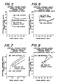
- Figures 5 and 6 show tests done respectively with instrumented track and with instrumented wheel sets on jointed railroad track which represents a typical staggered jointed rail found on most main line tracks. Test runs were conducted at each 10 mile per hour speed increment starting at 20 miles per hour and ending at 70 miles per hour. A series of runs at each speed was conducted to provide a sufficient database to identify force values for each car type. The results of the two separate types of test indicated a very close relationship of vertical forces for both the 100 ton hopper car and the 125 ton double stack articulated wellcar with vertical isolator pads.
- the wellcars were loaded to 157,500 pounds and produced dynamic vertical forces similar to those produced by the 100 ton hopper cars loaded to 131,500 pounds.
- the difference in loading produced substantially no difference in the vertical impact forces. This is more noticeable when compared with the 125 ton hopper car in Figure 5 which shows considerably higher impact forces.
- the 100 ton hopper car exhibited strong vertical bounce resonance between 60 and 65 miles per hour, and in all tests, the 125 ton double stack car with vertical isolator pads exhibited lower vertical forces at the wheels than did the 100 ton hopper car without vertical isolator pads.
- Figures 9 and 10 illustrate the data for the tests run on the balloon loop track which simulates lateral forces developed under track conditions having severe horizontal curves which may be sensitive to rail overturning or rail shifting.
- the balloon track is a continuous 7.5° horizontal curve having about 41 ⁇ 2 inches of super elevation.
- the test were conducted from 20 miles per hour to 45 miles per hour with the balance speed being approximately at 30 miles per hour.
- Figure 9 shows a range of lateral wheel forces from 7,000 to 9,000 pounds on the 125 ton vertical isolator pad double stack car compared to a range of 10,000 to 13,000 pounds on the 100 ton hopper car with the 125 ton hopper car being even higher.
- Figure 10 data taken with instrumented wheel sets shows that the lateral forces on the 100 ton hopper car wheels are much higher than when measured with the instrumented track, and that the forces on the wheels of the 125 ton vertical isolator pad double stack car was significantly lower than either of the other cars without the isolator pads.
- Figure 14 The critical comparative data shown in Figure 14 was obtained by testing the various pads in the test jig apparatus shown in Figures 12 and 13, to which attention should now be directed.
- Figures 12 and 13 show a test jig in which two vertical isolator pads 25 are shown clamped between a pair of outer plates 41 and an inner plate 42.
- the inner plate 42 is provided with stops 42A which prevent relative motion between the plate 42 and the pads 25 shown in Figure 2. These stops do not however prevent motion between the plate 42 and the form of pad shown in Figure 3 since the plates 33 and 34 are dimensionally shorter than the base of the Figure 2 pad.
- the bolts 43 and nuts 44 were tightened to exert 40,000 pounds of compressive load on the pads.
- One end of the jig was anchored by means of the clevis 45 and bolt 46, while the inner plate 42 was oscillated plus or minus one eighth of an inch at six Hertz until failure of the pads occurred.
- This test provides not only a static compressive load but a shearing load at right angles to the static load. Failure was determined by observing the force on the cycling plate 42 as the test progressed, beginning with the force at the very start of the test. While the pads were functioning properly this force was measurable on the order of between 10,000 and 15,000 pounds. However, when failure occurred there was a dramatic decrease in the measurable force, to on the order of 1,000 pounds.
- the testing showed that the pads started to show some sign of deterioration between 300,000 and 400,000 test cycles, and that by the time 600,000 cycles had been achieved, the pads of the type shown in Figure 3 of the drawings and the Miner pads had all failed. Based upon field failure data it appeared that 15 months was about the average time these pads failed, and corresponded to approximately 500,000 cycles in the testing scheme, representing about 300,000 miles of service.
- the isolator pads embodying to the invention were also tested in exactly the same way, with the result that these pads did not show any evidence of failure until a minimum of two million cycles had been achieved. After two million cycles the performance of the pad began to drop, but its drop was not precipitous as in the case of the failures of the Figure 3 type of pad. The performance started to drop off gradually until at about two and a half million cycles it began to drop more steeply, but nevertheless still in a controllable way, so that even at three million cycles the performance was still acceptable.
- the pads may be anchored or fixed or effectively fixed, against sliding movement relative to the bearing adaptor or equivalent by means other than the snug engagement of the lower surfaces of the pads in associated pockets.
- the upper surface of the pads could be fixed or effectively fixed, against sliding movement relative to the over lying parts of the truck sideframes or equivalent.
Landscapes
- Engineering & Computer Science (AREA)
- Mechanical Engineering (AREA)
- Railway Tracks (AREA)
Applications Claiming Priority (2)
| Application Number | Priority Date | Filing Date | Title |
|---|---|---|---|
| US506248 | 1990-04-09 | ||
| US07/506,248 US5081935A (en) | 1990-04-09 | 1990-04-09 | Railroad car vertical isolator pad |
Publications (2)
| Publication Number | Publication Date |
|---|---|
| EP0451399A2 true EP0451399A2 (fr) | 1991-10-16 |
| EP0451399A3 EP0451399A3 (en) | 1991-11-13 |
Family
ID=24013813
Family Applications (1)
| Application Number | Title | Priority Date | Filing Date |
|---|---|---|---|
| EP19900309721 Withdrawn EP0451399A3 (en) | 1990-04-09 | 1990-09-05 | Vertical isolator pad for a railroad car suspension system |
Country Status (4)
| Country | Link |
|---|---|
| US (1) | US5081935A (fr) |
| EP (1) | EP0451399A3 (fr) |
| AU (1) | AU637394B2 (fr) |
| CA (1) | CA2025132A1 (fr) |
Families Citing this family (36)
| Publication number | Priority date | Publication date | Assignee | Title |
|---|---|---|---|---|
| US5404826A (en) * | 1991-08-08 | 1995-04-11 | Pennsy Corporation | Bearing adapter for railway trucks having downward depending ends on adapter plate for protecting the adapter thrust lugs |
| US5562045A (en) * | 1995-04-05 | 1996-10-08 | Pennsy Corporation | Bearing adapter and adapter pad for railway trucks |
| US6142081A (en) * | 1998-05-07 | 2000-11-07 | Naco, Inc. | Pedestal rocker seat for providing passive axle steering to a rigid railway truck |
| US6659016B2 (en) * | 2001-08-01 | 2003-12-09 | National Steel Car Limited | Rail road freight car with resilient suspension |
| US7004079B2 (en) | 2001-08-01 | 2006-02-28 | National Steel Car Limited | Rail road car and truck therefor |
| US6895866B2 (en) | 2001-08-01 | 2005-05-24 | National Steel Car Limited | Rail road freight car with damped suspension |
| US7255048B2 (en) * | 2001-08-01 | 2007-08-14 | Forbes James W | Rail road car truck with rocking sideframe |
| US7096795B2 (en) * | 2003-05-06 | 2006-08-29 | Active Steering, Llc | Linear steering truck |
| US6874426B2 (en) | 2002-08-01 | 2005-04-05 | National Steel Car Limited | Rail road car truck with bearing adapter and method |
| US7823513B2 (en) | 2003-07-08 | 2010-11-02 | National Steel Car Limited | Rail road car truck |
| EP2058207B1 (fr) | 2003-07-08 | 2013-03-13 | National Steel Car Limited | Wagon de chemin de fer et ses éléments |
| US7631603B2 (en) * | 2004-12-03 | 2009-12-15 | National Steel Car Limited | Rail road car truck and bolster therefor |
| US20060137565A1 (en) * | 2004-12-23 | 2006-06-29 | National Steel Car Limited | Rail road car truck and bearing adapter fitting therefor |
| US7387074B2 (en) * | 2005-10-14 | 2008-06-17 | Asf-Keystone, Inc. | Railway truck bearing adapter |
| CN100441458C (zh) * | 2005-10-14 | 2008-12-10 | Asf-基斯通公司 | 铁道车辆支承轴承接套 |
| US7739961B2 (en) * | 2007-12-21 | 2010-06-22 | Standard Car Truck Company | Low profile shear pad and adapter |
| US7926428B2 (en) * | 2008-09-16 | 2011-04-19 | Amsted Rail Company, Inc. | Railway truck with bearing adapter |
| US8128076B2 (en) * | 2008-11-07 | 2012-03-06 | Itt Manfacturing Enterprises, Inc. | Noise attenuator for side wall panel |
| US20100248884A1 (en) * | 2009-03-31 | 2010-09-30 | Richard Tremblay | Transmission for an Electrically Powered Vehicle |
| US9637143B2 (en) * | 2013-12-30 | 2017-05-02 | Nevis Industries Llc | Railcar truck roller bearing adapter pad systems |
| US9216450B2 (en) | 2011-05-17 | 2015-12-22 | Nevis Industries Llc | Side frame and bolster for a railway truck and method for manufacturing same |
| US7966946B1 (en) * | 2010-10-21 | 2011-06-28 | Amsted Rail Company, Inc. | Railway truck pedestal bearing adapter |
| US8567320B2 (en) * | 2011-01-24 | 2013-10-29 | Pennsy Corporation | Resilient pad for railroad vehicle |
| US9233416B2 (en) | 2011-05-17 | 2016-01-12 | Nevis Industries Llc | Side frame and bolster for a railway truck and method for manufacturing same |
| US9346098B2 (en) | 2011-05-17 | 2016-05-24 | Nevis Industries Llc | Side frame and bolster for a railway truck and method for manufacturing same |
| US12291247B2 (en) | 2013-12-30 | 2025-05-06 | Nevis Industries Llc | Railcar truck roller bearing adapter-pad systems |
| US9758181B2 (en) | 2013-12-30 | 2017-09-12 | Nevis Industries Llc | Railcar truck roller bearing adapter pad systems |
| US10358151B2 (en) * | 2013-12-30 | 2019-07-23 | Nevis Industries Llc | Railcar truck roller bearing adapter-pad systems |
| US10569790B2 (en) * | 2013-12-30 | 2020-02-25 | Nevis Industries Llc | Railcar truck roller bearing adapter-pad systems |
| USD753544S1 (en) | 2014-12-05 | 2016-04-12 | Nevis Industries Llc | Adapter pad for railcar truck |
| USD762521S1 (en) | 2014-12-05 | 2016-08-02 | Nevis Industries Llc | Adapter for railcar truck |
| USD762520S1 (en) | 2014-12-05 | 2016-08-02 | Nevis Industries Llc | Adapter pad for railcar truck |
| USD753545S1 (en) | 2014-12-05 | 2016-04-12 | Nevis Industries Llc | Adapter pad for railcar truck |
| USD753022S1 (en) | 2014-12-05 | 2016-04-05 | Nevis Industries Llc | Adapter pad for railcar truck |
| USD753547S1 (en) | 2015-05-13 | 2016-04-12 | Nevis Industries Llc | Adapter pad for railcar truck |
| USD753546S1 (en) | 2015-05-13 | 2016-04-12 | Nevis Industries Llc | Adapter pad for railcar truck |
Family Cites Families (11)
| Publication number | Priority date | Publication date | Assignee | Title |
|---|---|---|---|---|
| US2100065A (en) * | 1936-05-22 | 1937-11-23 | Timken Roller Bearing Co | Truck |
| US3381629A (en) * | 1965-07-01 | 1968-05-07 | Buckeye Steel Castings Co | Cushion mounted bearing adaptor for railway trucks |
| US3638582A (en) * | 1969-12-03 | 1972-02-01 | Buckeye Steel Castings Co | Resilient bearing mounting |
| US3785298A (en) * | 1972-02-16 | 1974-01-15 | Buckeye Steel Castings Co | Cushion mounting bearing adaptor for railway trucks |
| US3965825A (en) * | 1974-10-08 | 1976-06-29 | Lord Corporation | Resilient truck axle bearing mounting |
| US4413569A (en) * | 1979-07-02 | 1983-11-08 | Amsted Industries Incorporated | Steering railroad truck |
| SE8003125L (sv) * | 1979-07-26 | 1981-01-27 | Amsted Ind Inc | Anordning for boggi hos jernvegsvagn |
| US4363278A (en) * | 1980-09-11 | 1982-12-14 | Amsted Industries Incorporated | Resilient railway truck bearing adaptor |
| US4433629A (en) * | 1981-12-09 | 1984-02-28 | General Motors Corporation | Railway truck bearing mounting assembly |
| US4830347A (en) * | 1983-05-23 | 1989-05-16 | Marathon Oil Company | Assembly for and a method of absorbing impact shock loads |
| DE3802580A1 (de) * | 1988-01-29 | 1989-08-10 | Maurer Friedrich Soehne | Topflager fuer bauwerke wie bruecken und dgl. |
-
1990
- 1990-04-09 US US07/506,248 patent/US5081935A/en not_active Expired - Fee Related
- 1990-08-30 AU AU61977/90A patent/AU637394B2/en not_active Ceased
- 1990-09-05 EP EP19900309721 patent/EP0451399A3/en not_active Withdrawn
- 1990-09-12 CA CA002025132A patent/CA2025132A1/fr not_active Abandoned
Also Published As
| Publication number | Publication date |
|---|---|
| CA2025132A1 (fr) | 1991-10-10 |
| AU6197790A (en) | 1991-10-10 |
| US5081935A (en) | 1992-01-21 |
| AU637394B2 (en) | 1993-05-27 |
| EP0451399A3 (en) | 1991-11-13 |
Similar Documents
| Publication | Publication Date | Title |
|---|---|---|
| US5081935A (en) | Railroad car vertical isolator pad | |
| Dukkipati et al. | Impact loads due to wheel flats and shells | |
| US4915031A (en) | Railway truck damping assembly | |
| US4444122A (en) | Primary suspension system for a railway car | |
| US7775163B2 (en) | Rail road car and bearing adapter fittings therefor | |
| US3961584A (en) | Railway car truck | |
| CN110920654B (zh) | 轨道车转向架滚柱轴承适配器垫系统 | |
| CN102765403B (zh) | 火车车厢转向架和其构件 | |
| US4230047A (en) | Railway truck bolster friction assembly | |
| US3785298A (en) | Cushion mounting bearing adaptor for railway trucks | |
| CA1075750A (fr) | Palier lateral de bogie ferroviaire | |
| EP0279094A1 (fr) | Semelle atténuant l'impact et les vibrations | |
| US20230365167A1 (en) | Railcar Truck Roller Bearing Adapter-Pad Systems | |
| JPH0211462A (ja) | 鉄道車輌用弾性サイドベアリング | |
| USRE31784E (en) | Railway truck bolster friction assembly | |
| CA2031649A1 (fr) | Amortisseurs pour traverses de plates-formes ferroviaires | |
| US5046431A (en) | Railway truck | |
| Stichel | On freight wagon dynamics and track deterioration | |
| CA1079758A (fr) | Materiel pour le pesage de materiel roulant ferroviaire | |
| US4771704A (en) | Damping device in a bogie for a railbound vehicle | |
| CA1234722A (fr) | Bogie sans chassis transversal | |
| US12291247B2 (en) | Railcar truck roller bearing adapter-pad systems | |
| CN113329929B (zh) | 铁轨车旁承 | |
| Fries et al. | Experimental investigation of freight car lateral dynamics | |
| RU195946U1 (ru) | Тележка подвижного состава железных дорог |
Legal Events
| Date | Code | Title | Description |
|---|---|---|---|
| PUAI | Public reference made under article 153(3) epc to a published international application that has entered the european phase |
Free format text: ORIGINAL CODE: 0009012 |
|
| PUAL | Search report despatched |
Free format text: ORIGINAL CODE: 0009013 |
|
| 17P | Request for examination filed |
Effective date: 19910726 |
|
| AK | Designated contracting states |
Kind code of ref document: A2 Designated state(s): AT BE DE FR GB IT NL SE |
|
| AK | Designated contracting states |
Kind code of ref document: A3 Designated state(s): AT BE DE FR GB IT NL SE |
|
| 17Q | First examination report despatched |
Effective date: 19930607 |
|
| STAA | Information on the status of an ep patent application or granted ep patent |
Free format text: STATUS: THE APPLICATION IS DEEMED TO BE WITHDRAWN |
|
| 18D | Application deemed to be withdrawn |
Effective date: 19941111 |