EP0451410A1 - Compresseur réfrigérant - Google Patents
Compresseur réfrigérant Download PDFInfo
- Publication number
- EP0451410A1 EP0451410A1 EP19900313230 EP90313230A EP0451410A1 EP 0451410 A1 EP0451410 A1 EP 0451410A1 EP 19900313230 EP19900313230 EP 19900313230 EP 90313230 A EP90313230 A EP 90313230A EP 0451410 A1 EP0451410 A1 EP 0451410A1
- Authority
- EP
- European Patent Office
- Prior art keywords
- valve plate
- set forth
- head
- suction
- preselected area
- Prior art date
- Legal status (The legal status is an assumption and is not a legal conclusion. Google has not performed a legal analysis and makes no representation as to the accuracy of the status listed.)
- Granted
Links
- 238000005057 refrigeration Methods 0.000 title claims abstract description 25
- 230000006835 compression Effects 0.000 claims abstract description 12
- 238000007906 compression Methods 0.000 claims abstract description 12
- 239000012530 fluid Substances 0.000 claims abstract description 12
- 238000007789 sealing Methods 0.000 claims description 5
- 239000003507 refrigerant Substances 0.000 claims description 3
- 230000009977 dual effect Effects 0.000 abstract 1
- 235000014676 Phragmites communis Nutrition 0.000 description 4
- 241000425571 Trepanes Species 0.000 description 2
- 230000009467 reduction Effects 0.000 description 2
- 230000008859 change Effects 0.000 description 1
- 230000007423 decrease Effects 0.000 description 1
- 230000000694 effects Effects 0.000 description 1
- 230000006872 improvement Effects 0.000 description 1
- 230000004048 modification Effects 0.000 description 1
- 238000012986 modification Methods 0.000 description 1
- 230000002093 peripheral effect Effects 0.000 description 1
- 238000004904 shortening Methods 0.000 description 1
- 238000004513 sizing Methods 0.000 description 1
Images


Classifications
-
- F—MECHANICAL ENGINEERING; LIGHTING; HEATING; WEAPONS; BLASTING
- F04—POSITIVE - DISPLACEMENT MACHINES FOR LIQUIDS; PUMPS FOR LIQUIDS OR ELASTIC FLUIDS
- F04B—POSITIVE-DISPLACEMENT MACHINES FOR LIQUIDS; PUMPS
- F04B39/00—Component parts, details, or accessories, of pumps or pumping systems specially adapted for elastic fluids, not otherwise provided for in, or of interest apart from, groups F04B25/00 - F04B37/00
- F04B39/10—Adaptations or arrangements of distribution members
- F04B39/1066—Valve plates
-
- F—MECHANICAL ENGINEERING; LIGHTING; HEATING; WEAPONS; BLASTING
- F04—POSITIVE - DISPLACEMENT MACHINES FOR LIQUIDS; PUMPS FOR LIQUIDS OR ELASTIC FLUIDS
- F04B—POSITIVE-DISPLACEMENT MACHINES FOR LIQUIDS; PUMPS
- F04B39/00—Component parts, details, or accessories, of pumps or pumping systems specially adapted for elastic fluids, not otherwise provided for in, or of interest apart from, groups F04B25/00 - F04B37/00
- F04B39/10—Adaptations or arrangements of distribution members
-
- F—MECHANICAL ENGINEERING; LIGHTING; HEATING; WEAPONS; BLASTING
- F04—POSITIVE - DISPLACEMENT MACHINES FOR LIQUIDS; PUMPS FOR LIQUIDS OR ELASTIC FLUIDS
- F04B—POSITIVE-DISPLACEMENT MACHINES FOR LIQUIDS; PUMPS
- F04B39/00—Component parts, details, or accessories, of pumps or pumping systems specially adapted for elastic fluids, not otherwise provided for in, or of interest apart from, groups F04B25/00 - F04B37/00
- F04B39/10—Adaptations or arrangements of distribution members
- F04B39/1073—Adaptations or arrangements of distribution members the members being reed valves
-
- Y—GENERAL TAGGING OF NEW TECHNOLOGICAL DEVELOPMENTS; GENERAL TAGGING OF CROSS-SECTIONAL TECHNOLOGIES SPANNING OVER SEVERAL SECTIONS OF THE IPC; TECHNICAL SUBJECTS COVERED BY FORMER USPC CROSS-REFERENCE ART COLLECTIONS [XRACs] AND DIGESTS
- Y10—TECHNICAL SUBJECTS COVERED BY FORMER USPC
- Y10T—TECHNICAL SUBJECTS COVERED BY FORMER US CLASSIFICATION
- Y10T137/00—Fluid handling
- Y10T137/7722—Line condition change responsive valves
- Y10T137/7837—Direct response valves [i.e., check valve type]
- Y10T137/7838—Plural
- Y10T137/7839—Dividing and recombining in a single flow path
Definitions
- the present invention relates generally to refrigeration compressors and more particularly to an improved valve plate assembly for use in such compressors.
- Refrigeration compressors of the reciprocating piston type generally incorporate a valve plate containing suction and discharge valves for controlling flow of refrigerant to and from one or more compression chambers.
- This valve plate is normally clamped between the compressor housing or block and the head.
- the head will generally include a suction chamber and discharge chamber communicating with the respective suction and discharge valves.
- valve plate It is generally desirable to minimize the thickness of the valve plate so as to minimize the volume of the discharge passages extending therethrough. This is important because compressed gas remaining in these passages upon completion of the compression stroke will reexpand thus reducing compressor volumetric efficiency.
- valve plate thickness As the valve plate thickness is reduced, its ability to resist pressure and thermal deflections decreases thus giving rise to possible leakage of discharge gas from the compression chamber in the head to the suction chamber or between adjacent cylinders in multiple piston type machines.
- valve plate in order to insure fluid tight sealing of the valve plate with both the compressor housing and head, it has not been possible to minimize the thickness of the valve plate and has been necessary to utilize larger numbers of closely spaced fasteners to secure the head and valve plate to the housing and/or more complicated head designs to minimize the presence of sealing surfaces on the valve plate in areas where the opposite surface of the valve is not fully supported (i.e. over the cylinder bore for example).
- the present invention overcomes the above noted difficulties by providing an improved valve plate assembly which incorporates oppositely bowed portions which serve to initially increase the compressive loading on the gaskets in selected areas so as to insure and maintain a fluid tight seal.
- This arrangement enables the thickness of the valve plate to be reduced thus improving the compressor's volumetric efficiency.
- greater freedom of design for the head is offered as a result of a reduction in the number of fasteners required for securing the head to the compressor housing. This reduction in the number of required fasteners also reduces the overall cost for parts and assembly labor.
- the present invention incorporates an improved suction valve assembly wherein a pair of reed type suction valves are secured to the valve plate at opposite ends of the valve members.
- This arrangement offers substantial improvement in the suction flow characteristics in that the maximum lift of each of the valves and hence maximum flow area therefor is at opposite ends of the two valves.
- the competition for flow between the adjacent valves is minimized and thus the spacing therebetween may be reduced, port size can be reduced and valve overlap can be increased.
- Refrigeration compressor 10 is of the hermetic reciprocating piston type and includes an outer shell 12 within which is disposed a compressor housing 14 having a pair of cylinder bores 16 and 18 provided therein in spaced side by side relationship within which pistons 20, 22 are reciprocatingly disposed.
- a head 24 is secured to compressor housing 14 with a valve plate assembly 26 being clamped therebetween.
- Pistons 20 and 22 are reciprocated by crankshaft 28 which in turn is rotatably driven by motor assembly 30.
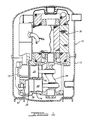
- valve plate assembly 26 comprises a relatively thin plate member 27 suitably sized to overlie both cylinders 16 and 18 and to thereby control flow of refrigerant to and from the compression chambers defined by the pistons 20, 22 and respective cylinders 16, 18.
- valve plate assembly includes a pair of spaced discharge passages 32, 34 and three suction passages 36, 38, 40 adapted to be positioned in overlying relationship to cylinder 16.
- a single reed type discharge valve (not shown) is secured to one side of valve plate 27 and operates to control flow from cylinder 16 to a discharge chamber 42 provided in head 24.
- a pair of elongated reed type suction valves 44, 46 are also secured to valve plate 27 in generally parallel spaced relationship with valve 44 overlying and controlling flow through passages 36, 38 and valve 46 controlling flow through passage 40. As shown in Figure 2, while suction valves 44 and 46 are positioned in parallel side by side relationship, they are secured to plate 27 at opposite ends by means of suitable fasteners such as rivets 48.
- a second set of substantially identical suction and discharge ports indicated by like numbers primed and associated valving (not shown) is also provided being positioned in overlying relationship to cylinder 18.
- this arrangement for securing the suction valves greatly improves the flow of suction gas into the respective cylinders 16 and 18 because the free ends of the two suction valves where maximum lift occurs and hence maximum gas flow occurs are located at opposite ends of the respective valves. Therefore flow competition therebetween is substantially eliminated.
- This improved suction gas flow thus enables the space between the suction valves to be reduced as well as allowing the length of the suction ports to be reduced. This allows more flexibility for positioning and sizing of the discharge ports. Additionally, shortening of the suction ports allows the tips of the valves to overlap the ports to a greater degree thereby reducing the energy required to open the valves as well as providing a cushioning effect as the valves close thus eliminating the need for trepan valve seats.
- head 24 includes a generally hollow interior which is divided into a discharge gas chamber 42 and a suction gas chamber 50 by means of wall 52 the outer edge of which is positioned in substantially coplanar relationship with the outer edge of peripheral flange portion 54. Suitable openings 56 are provided spaced around head 24 to accommodate fasteners for securing head 24 and valve plate 26 to compressor housing 14.
- discharge chamber 42 extends over both cylinders 16 and 18 and hence receives high pressure discharge gas via both sets of discharge passages 32, 34, 32', 34'.
- suction chamber 50 extends over both cylinders and supplies low pressure suction gas to both sets of suction passages.
- valve plate 26 incorporates a section 58 which is bowed outwardly in the direction toward head 24 as best seen with reference to Figure 4.
- Bowed section 58 has an overall length approximately equal to the distance between the sidewalls of cylinder 18 as indicated by points A and B in Figures 2 and 4 with a maximum height approximately at point C or midway between points A and B. As shown in Figures 2 and 4, this bowed area will span that area in which valve plate assembly overlies the discontinuity caused by the cylinder bore in the otherwise substantially planar surface 60 of compressor housing 14 and hence is not supported thereby.
- the raised surface caused by bowed portion 58 serves to cooperate with the opposed surface of wall 52 to initially exert a greater compressive force on gasket 62 within this area as compared to other areas wherein the valve plate is fully supported by surface 60.
- a substantially identically bowed area 58' as bowed portion 58 will also be provided in the area where valve plate assembly 26 overlies cylinder 18. This portion has been indicated by the same numbers and letters primed in Figure 2.
- valve plate 27 includes an area 64 extending approximately between points D and E wherein valve plate 27 is bowed in a direction toward compressor housing 14 so as to provide a raised surface area which will cooperate with surface 60 to initially increase the clamping force exerted on gasket 66 disposed therebetween.
- the area in which this raised or bowed portion 64 is located corresponds to the surface area between the adjacent cylinders and the area of the head in which the discharge chamber 42 is located.
- valve plate offers greater freedom in the design of the cylinder head and associated suction and discharge chambers as well as facilitating the use of thinner valve plates which, as noted above, result in improved compressor volumetric efficiency. Further, in some cases it is possible to achieve the requisite clamping force to insure proper sealing with fewer more widely spaced fasteners which also reduces costs and improves design flexibility.
Landscapes
- Engineering & Computer Science (AREA)
- Mechanical Engineering (AREA)
- General Engineering & Computer Science (AREA)
- Compressor (AREA)
Applications Claiming Priority (2)
| Application Number | Priority Date | Filing Date | Title |
|---|---|---|---|
| US07/504,875 US5073146A (en) | 1990-04-05 | 1990-04-05 | Compressor valving |
| US504875 | 1990-04-05 |
Publications (2)
| Publication Number | Publication Date |
|---|---|
| EP0451410A1 true EP0451410A1 (fr) | 1991-10-16 |
| EP0451410B1 EP0451410B1 (fr) | 1995-04-26 |
Family
ID=24008084
Family Applications (1)
| Application Number | Title | Priority Date | Filing Date |
|---|---|---|---|
| EP19900313230 Expired - Lifetime EP0451410B1 (fr) | 1990-04-05 | 1990-12-06 | Compresseur réfrigérant |
Country Status (5)
| Country | Link |
|---|---|
| US (1) | US5073146A (fr) |
| EP (1) | EP0451410B1 (fr) |
| KR (1) | KR910018672A (fr) |
| DE (1) | DE69018965T2 (fr) |
| ES (1) | ES2066743T3 (fr) |
Families Citing this family (11)
| Publication number | Priority date | Publication date | Assignee | Title |
|---|---|---|---|---|
| US5683235A (en) * | 1995-03-28 | 1997-11-04 | Dresser-Rand Company | Head port sealing gasket for a compressor |
| US6012908A (en) * | 1996-01-23 | 2000-01-11 | Matsushita Refrigeration Company | Electrically operated seal compressor having a refrigerant flow branch tube with a chamber disposed in the vicinity of a suction port |
| AUPQ221499A0 (en) * | 1999-08-13 | 1999-09-02 | Orbital Engine Company (Australia) Proprietary Limited | Compressor valve arrangement |
| US6899199B2 (en) * | 2002-10-24 | 2005-05-31 | Barnes Group Inc. | Flapper finger valve assembly |
| US20040222594A1 (en) * | 2003-05-08 | 2004-11-11 | Dresser-Rand Company | Oil film sealing device for a rotating shaft |
| US20060016483A1 (en) * | 2004-07-20 | 2006-01-26 | Barnes Group Inc. | Valve or valve plate having an integrated gasket |
| WO2009045462A1 (fr) * | 2007-10-02 | 2009-04-09 | Emerson Climate Technologies, Inc. | Compresseur équipé d'une plaque porte-soupape améliorée |
| US20130055887A1 (en) * | 2011-09-02 | 2013-03-07 | Allied Healthcare Products Inc. | Multiple valve head compressor apparatus |
| US10125756B2 (en) | 2014-12-22 | 2018-11-13 | Bendix Commercial Vehicle Systems Llc | System and method for reducing at least one of airflow turbulence and pressure fluctuation proximate a valve |
| US10436187B2 (en) | 2015-10-29 | 2019-10-08 | Emerson Climate Technologies, Inc. | Cylinder head assembly for reciprocating compressor |
| US11384759B2 (en) * | 2020-03-10 | 2022-07-12 | Hanon Systems | Vapor injection double reed valve plate |
Citations (4)
| Publication number | Priority date | Publication date | Assignee | Title |
|---|---|---|---|---|
| US3241748A (en) * | 1964-07-27 | 1966-03-22 | Carrier Corp | Hermetic motor compressor unit |
| FR1573460A (fr) * | 1967-09-01 | 1969-07-04 | ||
| DD109930A5 (de) * | 1974-01-07 | 1974-11-20 | Hoerbiger Ventilwerke Ag | lamellenventil,insbesondere fuer verdichter |
| US4776776A (en) * | 1987-08-24 | 1988-10-11 | The Devilbiss Company | Small pump valve plate assembly |
Family Cites Families (15)
| Publication number | Priority date | Publication date | Assignee | Title |
|---|---|---|---|---|
| US51175A (en) * | 1865-11-28 | guild | ||
| US1453912A (en) * | 1922-09-07 | 1923-05-01 | Mckim C Buckley | Fuel mixer |
| US2064754A (en) * | 1936-04-30 | 1936-12-15 | Edmund M Ivens | Valve |
| AT320124B (de) * | 1973-06-28 | 1975-01-27 | Hoerbiger Ventilwerke Ag | Lamellenventil für Kolbenverdichter |
| US4730996A (en) * | 1985-07-29 | 1988-03-15 | Kabushiki Kaisha Toshiba | Rotary compressor with two discharge valves having different frequencies |
| JPS6288877A (ja) * | 1985-10-11 | 1987-04-23 | Hamamatsu Gasket Seisakusho:Kk | 金属ガスケツト |
| JPH0231632Y2 (fr) * | 1985-10-12 | 1990-08-27 | ||
| JPS62155375A (ja) * | 1985-12-27 | 1987-07-10 | Nippon Metal Gasket Kk | 金属ガスケツト |
| JPS62197684A (ja) * | 1986-02-26 | 1987-09-01 | Hitachi Ltd | スクロ−ル圧縮機 |
| US4630835A (en) * | 1986-03-13 | 1986-12-23 | Felt Products Mfg. Co. | Head gasket and sealing assembly for a V-engine at the intersection of a block, a head and an intake manifold cover |
| US4767124A (en) * | 1986-07-29 | 1988-08-30 | Ishikawa Gasket Co., Ltd. | Gasket for an internal combustion engine |
| JPS63158360A (ja) * | 1986-12-19 | 1988-07-01 | Honda Motor Co Ltd | 内燃機関用金属ガスケツト |
| JPH059512Y2 (fr) * | 1987-03-11 | 1993-03-09 | ||
| US4854839A (en) * | 1988-06-13 | 1989-08-08 | Copeland Corporation | Compressor valve assembly |
| US4898396A (en) * | 1988-08-11 | 1990-02-06 | Ishikawa Gasket Co., Ltd. | Steel laminate gasket |
-
1990
- 1990-04-05 US US07/504,875 patent/US5073146A/en not_active Expired - Lifetime
- 1990-12-06 ES ES90313230T patent/ES2066743T3/es not_active Expired - Lifetime
- 1990-12-06 EP EP19900313230 patent/EP0451410B1/fr not_active Expired - Lifetime
- 1990-12-06 DE DE69018965T patent/DE69018965T2/de not_active Expired - Lifetime
- 1990-12-24 KR KR1019900021649A patent/KR910018672A/ko not_active Withdrawn
Patent Citations (4)
| Publication number | Priority date | Publication date | Assignee | Title |
|---|---|---|---|---|
| US3241748A (en) * | 1964-07-27 | 1966-03-22 | Carrier Corp | Hermetic motor compressor unit |
| FR1573460A (fr) * | 1967-09-01 | 1969-07-04 | ||
| DD109930A5 (de) * | 1974-01-07 | 1974-11-20 | Hoerbiger Ventilwerke Ag | lamellenventil,insbesondere fuer verdichter |
| US4776776A (en) * | 1987-08-24 | 1988-10-11 | The Devilbiss Company | Small pump valve plate assembly |
Also Published As
| Publication number | Publication date |
|---|---|
| ES2066743T1 (es) | 1995-03-16 |
| ES2066743T3 (es) | 1995-07-16 |
| DE69018965D1 (de) | 1995-06-01 |
| DE69018965T2 (de) | 1995-08-24 |
| US5073146A (en) | 1991-12-17 |
| EP0451410B1 (fr) | 1995-04-26 |
| KR910018672A (ko) | 1991-11-30 |
Similar Documents
| Publication | Publication Date | Title |
|---|---|---|
| US5147190A (en) | Increased efficiency valve system for a fluid pumping assembly | |
| US4715790A (en) | Compressor having pulsating reducing mechanism | |
| US5073146A (en) | Compressor valving | |
| US5577901A (en) | Compressor with valve unit for controlling suction and discharge of fluid | |
| US4813852A (en) | Discharge arrangement of a compressor having a plurality of compression chambers | |
| KR100189577B1 (ko) | 왕복운동형 압축기 | |
| JPH08170588A (ja) | 往復動型圧縮機 | |
| US5709535A (en) | Multi-cylinder reciprocating compressor having improved discharge valve stopper assembly | |
| JPH08261154A (ja) | ピストン型圧縮機 | |
| EP0874155A3 (fr) | Compresseur à déplacement alternatif | |
| JPH059512Y2 (fr) | ||
| JPS5820394B2 (ja) | 流体吸排装置 | |
| US4761119A (en) | Compressor having pulsating reducing mechanism | |
| US4480965A (en) | Capacity modulation device for compressor | |
| KR880003478Y1 (ko) | 압축기의 맥동저감기구 | |
| US20050013717A1 (en) | Valve assembly of reciprocating compressor | |
| JPH0312672B2 (fr) | ||
| US9341174B2 (en) | Compressor | |
| US4764099A (en) | Compressor having discharge valve means adapted to enhance the coefficient of performance of the compressor | |
| US4949982A (en) | Compressor valve assembly | |
| JP2004183569A (ja) | 圧縮機の吐出弁機構 | |
| EP0799995B1 (fr) | Disposition des passages d'entrée-sortie pour un compresseur alternatif | |
| JPH1182302A (ja) | 往復式圧縮機 | |
| JPH1193834A (ja) | 往復式圧縮機 | |
| JP2000018160A (ja) | 往復式圧縮機 |
Legal Events
| Date | Code | Title | Description |
|---|---|---|---|
| PUAI | Public reference made under article 153(3) epc to a published international application that has entered the european phase |
Free format text: ORIGINAL CODE: 0009012 |
|
| AK | Designated contracting states |
Kind code of ref document: A1 Designated state(s): BE DE ES FR GB IT |
|
| 17P | Request for examination filed |
Effective date: 19920228 |
|
| 17Q | First examination report despatched |
Effective date: 19930402 |
|
| GRAA | (expected) grant |
Free format text: ORIGINAL CODE: 0009210 |
|
| AK | Designated contracting states |
Kind code of ref document: B1 Designated state(s): BE DE ES FR GB IT |
|
| PG25 | Lapsed in a contracting state [announced via postgrant information from national office to epo] |
Ref country code: BE Effective date: 19950426 |
|
| REF | Corresponds to: |
Ref document number: 69018965 Country of ref document: DE Date of ref document: 19950601 |
|
| ITF | It: translation for a ep patent filed | ||
| REG | Reference to a national code |
Ref country code: ES Ref legal event code: FG2A Ref document number: 2066743 Country of ref document: ES Kind code of ref document: T3 |
|
| ET | Fr: translation filed | ||
| PLBE | No opposition filed within time limit |
Free format text: ORIGINAL CODE: 0009261 |
|
| STAA | Information on the status of an ep patent application or granted ep patent |
Free format text: STATUS: NO OPPOSITION FILED WITHIN TIME LIMIT |
|
| 26N | No opposition filed | ||
| PGFP | Annual fee paid to national office [announced via postgrant information from national office to epo] |
Ref country code: ES Payment date: 19971209 Year of fee payment: 8 |
|
| PG25 | Lapsed in a contracting state [announced via postgrant information from national office to epo] |
Ref country code: ES Free format text: LAPSE BECAUSE OF NON-PAYMENT OF DUE FEES Effective date: 19991207 |
|
| REG | Reference to a national code |
Ref country code: GB Ref legal event code: IF02 |
|
| REG | Reference to a national code |
Ref country code: ES Ref legal event code: FD2A Effective date: 20000114 |
|
| REG | Reference to a national code |
Ref country code: GB Ref legal event code: 732E |
|
| REG | Reference to a national code |
Ref country code: FR Ref legal event code: TP |
|
| PGFP | Annual fee paid to national office [announced via postgrant information from national office to epo] |
Ref country code: GB Payment date: 20091229 Year of fee payment: 20 Ref country code: FR Payment date: 20100106 Year of fee payment: 20 |
|
| PGFP | Annual fee paid to national office [announced via postgrant information from national office to epo] |
Ref country code: IT Payment date: 20091230 Year of fee payment: 20 |
|
| PGFP | Annual fee paid to national office [announced via postgrant information from national office to epo] |
Ref country code: DE Payment date: 20091230 Year of fee payment: 20 |
|
| REG | Reference to a national code |
Ref country code: GB Ref legal event code: PE20 Expiry date: 20101205 |
|
| PG25 | Lapsed in a contracting state [announced via postgrant information from national office to epo] |
Ref country code: GB Free format text: LAPSE BECAUSE OF EXPIRATION OF PROTECTION Effective date: 20101205 |
|
| PG25 | Lapsed in a contracting state [announced via postgrant information from national office to epo] |
Ref country code: DE Free format text: LAPSE BECAUSE OF EXPIRATION OF PROTECTION Effective date: 20101206 |