EP0451414B1 - Interrupteur à bouton poussoir - Google Patents
Interrupteur à bouton poussoir Download PDFInfo
- Publication number
- EP0451414B1 EP0451414B1 EP90313936A EP90313936A EP0451414B1 EP 0451414 B1 EP0451414 B1 EP 0451414B1 EP 90313936 A EP90313936 A EP 90313936A EP 90313936 A EP90313936 A EP 90313936A EP 0451414 B1 EP0451414 B1 EP 0451414B1
- Authority
- EP
- European Patent Office
- Prior art keywords
- push button
- contacts
- housing
- end portions
- switch assembly
- Prior art date
- Legal status (The legal status is an assumption and is not a legal conclusion. Google has not performed a legal analysis and makes no representation as to the accuracy of the status listed.)
- Expired - Lifetime
Links
- 239000004020 conductor Substances 0.000 claims description 6
- 229910052751 metal Inorganic materials 0.000 claims description 5
- 239000002184 metal Substances 0.000 claims description 5
- 230000001154 acute effect Effects 0.000 claims description 2
- 230000000994 depressogenic effect Effects 0.000 claims description 2
- 230000000881 depressing effect Effects 0.000 abstract description 2
- 238000010276 construction Methods 0.000 description 3
- DHKHKXVYLBGOIT-UHFFFAOYSA-N acetaldehyde Diethyl Acetal Natural products CCOC(C)OCC DHKHKXVYLBGOIT-UHFFFAOYSA-N 0.000 description 2
- 230000000712 assembly Effects 0.000 description 2
- 238000000429 assembly Methods 0.000 description 2
- 229920001577 copolymer Polymers 0.000 description 2
- 238000003780 insertion Methods 0.000 description 2
- 230000037431 insertion Effects 0.000 description 2
- 238000010079 rubber tapping Methods 0.000 description 2
- 229920013683 Celanese Polymers 0.000 description 1
- 229920005123 Celcon® Polymers 0.000 description 1
- DMFGNRRURHSENX-UHFFFAOYSA-N beryllium copper Chemical compound [Be].[Cu] DMFGNRRURHSENX-UHFFFAOYSA-N 0.000 description 1
- 230000006835 compression Effects 0.000 description 1
- 238000007906 compression Methods 0.000 description 1
- 239000000463 material Substances 0.000 description 1
- 230000000630 rising effect Effects 0.000 description 1
Images
Classifications
-
- H—ELECTRICITY
- H01—ELECTRIC ELEMENTS
- H01H—ELECTRIC SWITCHES; RELAYS; SELECTORS; EMERGENCY PROTECTIVE DEVICES
- H01H13/00—Switches having rectilinearly-movable operating part or parts adapted for pushing or pulling in one direction only, e.g. push-button switch
-
- F—MECHANICAL ENGINEERING; LIGHTING; HEATING; WEAPONS; BLASTING
- F21—LIGHTING
- F21V—FUNCTIONAL FEATURES OR DETAILS OF LIGHTING DEVICES OR SYSTEMS THEREOF; STRUCTURAL COMBINATIONS OF LIGHTING DEVICES WITH OTHER ARTICLES, NOT OTHERWISE PROVIDED FOR
- F21V23/00—Arrangement of electric circuit elements in or on lighting devices
- F21V23/04—Arrangement of electric circuit elements in or on lighting devices the elements being switches
-
- H—ELECTRICITY
- H01—ELECTRIC ELEMENTS
- H01H—ELECTRIC SWITCHES; RELAYS; SELECTORS; EMERGENCY PROTECTIVE DEVICES
- H01H13/00—Switches having rectilinearly-movable operating part or parts adapted for pushing or pulling in one direction only, e.g. push-button switch
- H01H13/02—Details
- H01H13/023—Light-emitting indicators
Definitions
- the present invention relates to push button switch assemblies, and, more particularly, to illuminated push button switche assemblies commonly used in connection with door bells, chimes or the like.
- buttons of this type have been made with at least a dozen parts including a helical compression spring, contacts, screws, a bulb, a button and a housing. Both the cost of producing the individual parts and the cost of assembly have been higher than need be.
- DE-A-2610713 discloses a push button switch assembly comprising in combination a housing, a pair of spaced apart electrically conductive spring metal contacts, a push button coupled to said housing for travel relative thereto, and means for separately connecting to each of said contacts a respective external electrical conductor, said contacts being disposed within said housing for engagement by said push button which upon depression causes said contacts to flex and engage for completing a circuit for an external source through said means for connecting said external electrical conductors, said contacts being interposed between said push button and said housing for exerting a spring return force upon said push button.
- the present invention provides such an assembly characterised in that an electrically energizable light emitting device is located in a space between said contacts for illuminating said assembly, said contacts being mounted in said housing in electrical contact with respective means for establishing an electrical connection to said light emitting device whereby engagement of said contacts for completing said circuit shunts said light emitting device, end portions of said contacts engageable by said push button being bifurcated for providing an opening through which light emitted by said light emitting device can reach the inner surface of said push button.
- said push button has an inner surface that engages both of said contacts, said contacts each comprising an elongated strip of said conductive spring metal with a first end portion secured to said housing, said end portions of said contacts engageable with said push button comprising respective second end portions extending cantilevered from the said first end portions into contact with said inner surface of the push button at an acute angle relative to the direction of movement of said push button, the second end portion of each contact extending toward and into non-engaging proximity with the second end portion of said other contact, whereby depression of said push button flexes both of said contact second end portions towards each other and into mutual contact.
- said first end portions of said contacts are secured to said housing at diametrically opposed locations on opposite sides of the axis of travel of said push button, said light emitting device is disposed between said first end portions of said contacts.
- the inner surface of said push button may have regions that are inclined relative to the normal to said axis of travel which regions are located for engagement by said second end portions of said contacts for providing a camming action to said contacts when said button is depressed.
- the light emitting device is a miniature bulb
- said housing has a central cavity for receiving said bulb
- said bulb has a pair of wire leads for connection each to a different one of said contacts, said wire leads being sandwiched between said first end portions of said contacts and a portion of said housing and forming said respective means for establishing an electrical connection to said light emitting device.
- the housing has a cylindrical counterbore surrounded by a wall and said push button is mounted in said counterbore for sliding movement relative to said housing axially of said counterbore
- said button has a head disposed at the upper end of said wall and a pair of elastic legs extending downwardly from said head toward the lower end of said wall, each of said legs having a barb at its lower end extending radially outwardly of the axis of said counterbore and said legs being spaced outwardly of said axis and being spaced from each other in the direction circumferentially of said axis, and said wall having a surface extending transversely to said axis with which said barbs are engageable for holding said button within said counterbore.
- the transversely extending wall surface may be at the bottom end of said wall.
- At least a part of said button head is translucent.
- the contacts are preferably secured to the housing by the means for connecting the conductors thereto.
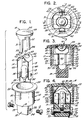
- the illuminated push button switch consists of a housing 10, two screws, 11 and 12, a miniature lamp 13, two contacts, 14 and 15, and a button 16.
- the housing 10 has a cylindrical body portion 17 and an integral mounting block portion 18.
- the housing 10, including the body portion 17 and the block portion 18, can be molded as a unit from a plastic, such as an acetal copolymer sold under the trademark "CELCON" by Hoechst Celanese Corp., Somerville, New Jersey.
- the portion 18, as shown, is joined to the base 19 of the cylindrical portion 17.
- the opposite end 20 of the cylindrical portion 17 has a cylindrical counterbore 21 that extends down into the cylindrical portion 17 and is surrounded by a wall.
- the mouth of the counterbore 21 is surrounded by a radially extending flange 22 tapered from a greater thickness at the mouth of the counterbore to a lesser thickness at its outer edge as shown in Figs. 3 and 4.
- the lower internal region of portion 17 has four radially inwardly extending blocks 23, 24, 25 and 26 separated circumferentially from each other thereby creating a cruciform cavity 27 having cavity arms radiating from a central cavity 28.
- the central cavity 28 is sized to receive with a loose fit the bulb 13 which is of a type known as a miniature bulb and generally contains a filament energizable by the relatively low voltage customarily used with bell or chime.
- the bulb 13 has a pair of were leads known as pigtail leads 29 and 30.
- the cylindrical portion 17 overhangs the block portion 18 and is provided with two openings, 31 and 32, in the bottom wall at the base 19 of the cylindrical portion 17.
- the openings 31 and 32 are of a size sufficient to accommodate the respective contact 14 or 15 which is passed therethrough after insertion of bulb 13.
- the contact 14 or 15 is passed through the corresponding opening 31 or 32 the contact encounters the corresponding lead 29 or 30 of bulb 13 carrying the lead downward and over the side face 33 or 34 of block 18 so as to capture the corresponding lead 29 or 30 between contact 14 or 15 and block face 33 or 34.
- screws 11 and 12 which are preferably self-tapping, through apertures 36 and 37, respectively, in contacts 14 and 15 into bores 38 and 39 in block 18 simultaneously secure the contacts 14 and 15 to block 18 and capture the bulb leads 29 and 30.
- the contacts 14 and 15 each has a rectangular end portion 40 and a slightly laterally diverging bifurcated end portion 41 inclined at a suitable angle cantilevered from portion 40.
- the arms 42 of the portion 41 end in a rolled over portion 43.
- the portions 41 of the contacts 14 and 15 are flexed and brought together by depressing the button 16 whose undersurface is provided with depressions bounded by inclined surfaces 44 that function as camming surfaces to cause the flexure of contact portions 41 until the portions 43 on opposing contacts 14 and 15 come into contacting engagement as shown by the dashed lines 45.
- the button 16 can be molded from a plastic, such as the acetal copolymer identified hereinbefore and has a translucent head 49, with a shallow generally spherical outer surface 50 and an inner surface provided with the surfaces 44.
- elastic legs 51 and 52 Depending from the head 49 are diametrally located, elastic legs 51 and 52 terminating in radial by outwardly extending projections or barbs 53 and 54, respectively.
- the legs 51 and 52 pass downward in counterbore 21 through the space between blocks 23 and 24 on one side and 25 and 26 on the other side until the barbs 53 and 54 pass through openings 55 and 56 in the bottom wall adjacent the side wall of cylindrical portion 17.
- the wall of the portion 17 may be provided with through openings into which the barbs 53 and 54 can extend. However, in each case the barbs 53 and 54 engage a surface extending transversly to the axis of sheling movement of the push button.
- the contacts 14 and 15 are made of suitable spring metal that also has good electrical conductivity. It is presently preferred to use beryllium copper for this purpose with the grain running lengthwise.
- the button 16 and housing 20 can be made of any suitable moldable plastic material.
- the housing 20 is provided with some means for securing the assembly in an escutcheon or the like.
- the housing 10 is intended to be mounted in an opening, bore or cavity and has a plurality of circumferentially spaced, radially projecting ribs 60 for gripping the wall of the cavity in the escutcheon.
- any suitable known means can be provided tailored to the particular design of the receptacle.
- the notch in the portion 41 which defines the bifurcation in contacts 14 and 15 should be sufficient to enable light from the bulb 13 to reach the head 49 of the button 16. It should be apparent that the screws 11 and 12, besides securing the contacts in the housing, also serve as the means for connecting wires thereto for establishing electrical connection of the bell or chime circuit to the switch assembly.
- the contacts 14 and 15 can each have a tab struck from the rectangular portion 40 an appropriate distance above the apertures 36 and 37 such that the tabs overlie and engage the respective bulb leads 29 and 30 when the contacts are installed in the housing 20.
- the tabs engaging the bulb leads will insure that the bulb cannot move out of position when the screws 11 and 12 are loosened.
Landscapes
- Engineering & Computer Science (AREA)
- General Engineering & Computer Science (AREA)
- Push-Button Switches (AREA)
- Switches With Compound Operations (AREA)
- Switch Cases, Indication, And Locking (AREA)
Claims (9)
- Ensemble commutateur à bouton-poussoir comprenant, en combinaison, un boîtier (10), une paire de contacts (14, 15) espacés l'un de l'autre, en un métal à ressort électriquement conducteur, un bouton-poussoir (16) assemblé audit boîtier de façon à pouvoir être déplacé par rapport à celui-ci, et des moyens (11, 12) pour raccorder séparément à chacun desdits contacts (14, 15) un conducteur électrique extérieur respectif, lesdits contacts (14, 15) étant positionnés à l'intérieur dudit boîtier (10) de façon à être saisis par ledit bouton-poussoir (16), lequel, lorsqu'il est enfoncé, fait fléchir lesdits contacts (14, 15) et les amène en prise mutuelle afin de fermer un circuit pour une source extérieure, au travers desdits moyens (11, 12) de raccordement desdits conducteurs électriques extérieurs, lesdits contacts (14, 15) étant interposés entre ledit bouton-poussoir (16) et ledit boîtier (10) de façon à exercer une force de rappel élastique sur ledit bouton-poussoir (16), caractérisé en ce qu'un dispositif émetteur de lumière (13), activable électriquement, est placé dans un espace présent entre lesdits contacts (14, 15) pour éclairer ledit ensemble, lesdits contacts (14, 15) étant, dans ledit boîtier, montés en contact électrique avec des moyens respectifs (29, 30) destinés à établir une connexion électrique avec ledit dispositif émetteur de lumière (13), lesdits contacts (14, 15), lorsqu'ils sont en prise mutuelle pour fermer ledit circuit, court-circuitant alors ledit dispositif émetteur de lumière (13), des parties d'extrémité (41) desdits contacts, aptes à être saisies par ledit bouton-poussoir, étant en forme de fourches pour ménager une ouverture à travers laquelle de la lumière émise par ledit dispositif émetteur de lumière (13) peut atteindre la surface intérieure dudit bouton-poussoir.
- Ensemble commutateur à bouton-poussoir selon la revendication 1, dans lequel ledit bouton-poussoir (16) présente une surface intérieure qui vient en prise avec l'un et l'autre desdits contacts (14, 15), lesdits contacts comprenant chacun une bande allongée faite dudit métal à ressort conducteur, ayant une première partie d'extrémité (40) assujettie audit boîtier, lesdites parties d'extrémité (41) desdits contacts, aptes à être saisies par ledit bouton-poussoir, comprenant des secondes parties d'extrémité respectives (41) qui s'étendent en porte-à-faux depuis lesdites premières parties d'extrémité, en contact avec ladite surface intérieure du bouton-poussoir, sous un angle aigu par rapport à la direction de déplacement dudit bouton-poussoir, les secondes parties d'extrémité (41) de chaque contact s'étendant en direction et jusqu'à proximité, sans la toucher, de la seconde partie d'extrémité (41) dudit autre contact, si bien qu'un enfoncement dudit bouton-poussoir fait fléchir l'une vers l'autre les deux dites secondes parties d'extrémité des contacts et les met en contact mutuel.
- Ensemble commutateur à bouton-poussoir selon la revendication 2, dans lequel lesdites premières parties d'extrémité (40) desdits contacts (14, 15) sont assujetties audit boîtier (10) en des emplacements diamétralement opposés, de part et d'autre de l'axe de déplacement dudit bouton-poussoir (16), et ledit dispositif émetteur de lumière (13) est disposé entre lesdites premières parties d'extrémité (40) desdits contacts.
- Ensemble commutateur à bouton-poussoir selon la revendication 2 ou 3, dans lequel ladite surface intérieure dudit bouton-poussoir présente des régions (44), qui sont inclinées par rapport à la perpendiculaire audit axe de déplacement, régions qui sont positionnées de façon à être saisies par lesdites secondes parties d'extrémité (41) desdits contacts, afin d'assurer un effet de came sur lesdits contacts, quand ledit bouton est enfoncé.
- Ensemble commutateur à bouton-poussoir selon la revendication 4, dans lequel ledit dispositif émetteur de lumière est une ampoule miniature (13), ledit boîtier présente une cavité centrale (28) destinée à recevoir ladite ampoule, ladite ampoule comporte une paire de fils conducteurs (29, 30) destinés chacun à être raccordés à un contact différent parmi lesdits contacts (14, 15), lesdits fils conducteurs étant enserrés entre lesdites premières parties d'extrémité (40) desdits contacts et une partie (18) dudit boîtier (10) et constituant lesdits moyens respectifs destinés à établir une connexion électrique avec ledit dispositif émetteur de lumière.
- Ensemble commutateur à bouton-poussoir selon l'une quelconque des revendications 1 à 5, dans lequel ledit boîtier (10) présente un alésage cylindrique (21) entouré par une paroi et ledit bouton-poussoir (16) est monté dans ledit alésage avec une possibilité de déplacement coulissant par rapport audit boîtier, dans la direction de l'axe dudit alésage, et ledit bouton comporte une tête (49) disposée à l'extrémité supérieure de ladite paroi et une paire de pattes élastiques (51, 52) s'étendant vers le bas depuis ladite tête en direction de l'extrémité inférieure de ladite paroi, chacune desdites pattes comportant, à son extrémité inférieure, un ergot (53, 54) qui s'étend radialement vers l'extérieur par rapport à l'axe dudit alésage, et lesdites pattes étant placées à distance dudit axe, vers l'extérieur de celui-ci, et étant espacées l'une de l'autre dans la direction circonférentielle autour dudit axe, tandis que ladite paroi présente une surface s'étendant transversalement audit axe, avec laquelle lesdits ergots peuvent venir en prise pour retenir ledit bouton à l'intérieur dudit alésage.
- Ensemble commutateur à bouton-poussoir selon la revendication 6, dans lequel ladite surface de paroi s'étendant transversalement se trouve à l'extrémité de base de ladite paroi.
- Ensemble commutateur à bouton-poussoir selon la revendication 6 ou 7, dans lequel au moins une partie (49) de ladite tête du bouton est translucide.
- Ensemble commutateur à bouton-poussoir selon l'une quelconque des revendications 1 à 8, dans lequel lesdits contacts (14, 15) sont assujettis audit boîtier (10) par lesdits moyens (12, 13) de raccordement desdits conducteurs auxdits contacts.
Applications Claiming Priority (2)
| Application Number | Priority Date | Filing Date | Title |
|---|---|---|---|
| US07/506,469 US5036441A (en) | 1990-04-09 | 1990-04-09 | Illuminated push button |
| US506469 | 1990-04-09 |
Publications (2)
| Publication Number | Publication Date |
|---|---|
| EP0451414A1 EP0451414A1 (fr) | 1991-10-16 |
| EP0451414B1 true EP0451414B1 (fr) | 1996-02-14 |
Family
ID=24014725
Family Applications (1)
| Application Number | Title | Priority Date | Filing Date |
|---|---|---|---|
| EP90313936A Expired - Lifetime EP0451414B1 (fr) | 1990-04-09 | 1990-12-19 | Interrupteur à bouton poussoir |
Country Status (8)
| Country | Link |
|---|---|
| US (1) | US5036441A (fr) |
| EP (1) | EP0451414B1 (fr) |
| KR (1) | KR910019080A (fr) |
| CN (1) | CN1025525C (fr) |
| AT (1) | ATE134277T1 (fr) |
| CA (1) | CA2030590C (fr) |
| DE (1) | DE69025396D1 (fr) |
| MX (1) | MX171909B (fr) |
Families Citing this family (19)
| Publication number | Priority date | Publication date | Assignee | Title |
|---|---|---|---|---|
| US5140116A (en) * | 1989-09-19 | 1992-08-18 | Schmitt Walter Stefan | Illuminated push-button switch |
| US5392202A (en) * | 1994-05-13 | 1995-02-21 | Fred M. Schildwachter & Sons, Inc. | Low profile illuminated push button |
| JP3518914B2 (ja) * | 1994-12-07 | 2004-04-12 | 本田技研工業株式会社 | 電動車両用モータの防水構造 |
| US6770829B1 (en) * | 2003-10-02 | 2004-08-03 | Eaton Corporation | Control apparatus |
| US6991345B2 (en) * | 2003-12-20 | 2006-01-31 | Jacek Helenowski | Portable light source with mirror |
| US20060209484A1 (en) * | 2005-03-16 | 2006-09-21 | Roell Robb R | Illuminated pushbutton switch assembly |
| US7180021B2 (en) * | 2005-04-05 | 2007-02-20 | Desa Ip, Llc | LED illuminated door chime push button with adjustable task light |
| TW200729261A (en) * | 2006-01-19 | 2007-08-01 | Benq Corp | Switch with light emitting function |
| AU316528S (en) * | 2007-08-01 | 2007-10-04 | Caroma Industries Ltd | A button assembly |
| AU316530S (en) * | 2007-08-01 | 2007-10-04 | Caroma Industries Ltd | A button assembly |
| AU316529S (en) * | 2007-08-01 | 2007-10-04 | Caroma Industries Ltd | A button assembly |
| AU316532S (en) * | 2007-08-01 | 2007-10-04 | Caroma Industries Ltd | A button assembly |
| AU316531S (en) * | 2007-08-01 | 2007-10-04 | Caroma Industries Ltd | A button assembly |
| US7819456B2 (en) * | 2008-01-09 | 2010-10-26 | Toyota Motor Engineering & Manufacturing North America, Inc. | Instrument panel covers with lockout ribs |
| US7878676B2 (en) * | 2008-08-20 | 2011-02-01 | Jacek Helenowski | Cosmetic housing |
| USD602637S1 (en) | 2008-08-20 | 2009-10-20 | Jacek Helenowski | Cosmetic holder |
| CN102568890A (zh) * | 2010-12-21 | 2012-07-11 | 富泰华工业(深圳)有限公司 | 电源按钮及采用该电源按钮的电子装置 |
| US20140062714A1 (en) * | 2012-09-05 | 2014-03-06 | Robert W. Chvatal | Flashing doorbell security lamp |
| US9101193B1 (en) * | 2014-08-25 | 2015-08-11 | Chuen Churn Co., Ltd. | Illuminating cosmetic applicator |
Family Cites Families (15)
| Publication number | Priority date | Publication date | Assignee | Title |
|---|---|---|---|---|
| DE584151C (de) * | 1930-02-28 | 1933-09-15 | Aeg | Beleuchtungseinrichtung fuer Installationsapparate |
| US2802082A (en) * | 1955-12-02 | 1957-08-06 | Trine Mfg Corp | Electric switch |
| US3309697A (en) * | 1963-12-26 | 1967-03-14 | Ford Motor Co | Seat belt reminder indicating switch |
| DE1765641A1 (de) * | 1968-06-22 | 1971-09-02 | Bosch Gmbh Robert | Schalter,insbesondere fuer Kraftfahrzeuge |
| DE1811394B2 (de) * | 1968-11-28 | 1971-12-09 | Blaupunkt Werke GmbH, 3200 Hildes heim | Schiebeschalter in kleinbauweise |
| US3590234A (en) * | 1970-03-06 | 1971-06-29 | Alfred M Bartick | Keyhole-illuminating device with time delay |
| US3934105A (en) * | 1974-05-09 | 1976-01-20 | Amp Incorporated | Miniature switch with lighted indicator |
| US3989912A (en) * | 1975-01-23 | 1976-11-02 | Illinois Tool Works Inc. | Lighted pushbutton electrical switch |
| DE2610713C3 (de) * | 1976-03-13 | 1979-10-11 | Fa. Leopold Kostal, 5880 Luedenscheid | Druckknopf-Tastschalter |
| US4293894A (en) * | 1980-03-17 | 1981-10-06 | Blank Nolan D | Battery operated illuminating device |
| DE3145802A1 (de) * | 1981-11-19 | 1983-05-26 | Wolfgang 2210 Itzehoe Priesemuth | Schaltkontkatanordnung und verfahren zu ihrer herstellung |
| DE3324254A1 (de) * | 1983-07-06 | 1985-01-17 | Rudolf Schadow Gmbh, 1000 Berlin | Kontaktfedersatz |
| JPS6086766U (ja) * | 1983-11-16 | 1985-06-14 | ナイルス部品株式会社 | 自動車用シガ−ライタ− |
| US4694130A (en) * | 1986-08-29 | 1987-09-15 | General Motors Corporation | Illuminated pushbutton switch with unitary spring and contact |
| US4745527A (en) * | 1987-01-09 | 1988-05-17 | Allison Corporation | Illuminated door lock scratch guard |
-
1990
- 1990-04-09 US US07/506,469 patent/US5036441A/en not_active Expired - Lifetime
- 1990-11-23 CA CA002030590A patent/CA2030590C/fr not_active Expired - Fee Related
- 1990-12-10 MX MX023666A patent/MX171909B/es unknown
- 1990-12-18 CN CN90110050A patent/CN1025525C/zh not_active Expired - Fee Related
- 1990-12-19 EP EP90313936A patent/EP0451414B1/fr not_active Expired - Lifetime
- 1990-12-19 AT AT90313936T patent/ATE134277T1/de not_active IP Right Cessation
- 1990-12-19 DE DE69025396T patent/DE69025396D1/de not_active Expired - Lifetime
-
1991
- 1991-03-15 KR KR1019910004102A patent/KR910019080A/ko not_active Withdrawn
Also Published As
| Publication number | Publication date |
|---|---|
| MX171909B (es) | 1993-11-23 |
| DE69025396D1 (de) | 1996-03-28 |
| US5036441A (en) | 1991-07-30 |
| CA2030590A1 (fr) | 1991-10-10 |
| CN1055622A (zh) | 1991-10-23 |
| ATE134277T1 (de) | 1996-02-15 |
| CA2030590C (fr) | 1994-09-27 |
| CN1025525C (zh) | 1994-07-20 |
| EP0451414A1 (fr) | 1991-10-16 |
| KR910019080A (ko) | 1991-11-30 |
Similar Documents
| Publication | Publication Date | Title |
|---|---|---|
| EP0451414B1 (fr) | Interrupteur à bouton poussoir | |
| US4177367A (en) | Push button switch | |
| US4331851A (en) | Printed circuit board having data input devices mounted thereon and input devices therefor | |
| US4163879A (en) | Selector switch | |
| US5263881A (en) | Socket for halogen bulb | |
| US5201410A (en) | Push-button switches | |
| US4825020A (en) | Slide switch | |
| US3995129A (en) | Key switch component | |
| CA2129408A1 (fr) | Ensemble de connexion par encliquetage | |
| US5392202A (en) | Low profile illuminated push button | |
| US3934104A (en) | Push-button switch | |
| US4154997A (en) | Miniature multi-contact pushbutton switch | |
| US4874913A (en) | Luminous element holding structure for an illuminated key switch | |
| KR0149161B1 (ko) | 키보드 스위치의 제조방법 및 키보드 스위치 | |
| US7202429B2 (en) | Switch with light supported in operating member | |
| US4227163A (en) | Electrical keyswitch | |
| EP0101958B1 (fr) | Interrupteur à bouton poussoir | |
| US4837411A (en) | Spring switch | |
| US4431880A (en) | Rocker switch with integrally defined retention means for resistor and lamp | |
| KR100381942B1 (ko) | 푸시버튼 스위치 | |
| GB2105911A (en) | Illuminated push-button switch | |
| GB2256323A (en) | Electrical trailing socket with switches | |
| JP2001250450A (ja) | 押釦スイッチ | |
| JPH0245939Y2 (fr) | ||
| US4410773A (en) | Multipole data switch |
Legal Events
| Date | Code | Title | Description |
|---|---|---|---|
| PUAI | Public reference made under article 153(3) epc to a published international application that has entered the european phase |
Free format text: ORIGINAL CODE: 0009012 |
|
| AK | Designated contracting states |
Kind code of ref document: A1 Designated state(s): AT BE CH DE DK ES FR GB GR IT LI LU NL SE |
|
| 17P | Request for examination filed |
Effective date: 19911210 |
|
| 17Q | First examination report despatched |
Effective date: 19940127 |
|
| GRAA | (expected) grant |
Free format text: ORIGINAL CODE: 0009210 |
|
| AK | Designated contracting states |
Kind code of ref document: B1 Designated state(s): AT BE CH DE DK ES FR GB GR IT LI LU NL SE |
|
| PG25 | Lapsed in a contracting state [announced via postgrant information from national office to epo] |
Ref country code: IT Free format text: LAPSE BECAUSE OF FAILURE TO SUBMIT A TRANSLATION OF THE DESCRIPTION OR TO PAY THE FEE WITHIN THE PRE;WARNING: LAPSES OF ITALIAN PATENTS WITH EFFECTIVE DATE BEFORE 2007 MAY HAVE OCCURRED AT ANY TIME BEFORE 2007. THE CORRECT EFFECTIVE DATE MAY BE DIFFERENT FROM THE ONE RECORDED.SCRIBED TIME-LIMIT Effective date: 19960214 Ref country code: ES Free format text: THE PATENT HAS BEEN ANNULLED BY A DECISION OF A NATIONAL AUTHORITY Effective date: 19960214 Ref country code: NL Free format text: LAPSE BECAUSE OF FAILURE TO SUBMIT A TRANSLATION OF THE DESCRIPTION OR TO PAY THE FEE WITHIN THE PRESCRIBED TIME-LIMIT Effective date: 19960214 Ref country code: LI Effective date: 19960214 Ref country code: GR Free format text: LAPSE BECAUSE OF FAILURE TO SUBMIT A TRANSLATION OF THE DESCRIPTION OR TO PAY THE FEE WITHIN THE PRESCRIBED TIME-LIMIT Effective date: 19960214 Ref country code: BE Effective date: 19960214 Ref country code: DK Effective date: 19960214 Ref country code: AT Effective date: 19960214 Ref country code: CH Effective date: 19960214 Ref country code: FR Effective date: 19960214 |
|
| REF | Corresponds to: |
Ref document number: 134277 Country of ref document: AT Date of ref document: 19960215 Kind code of ref document: T |
|
| REF | Corresponds to: |
Ref document number: 69025396 Country of ref document: DE Date of ref document: 19960328 |
|
| PG25 | Lapsed in a contracting state [announced via postgrant information from national office to epo] |
Ref country code: SE Effective date: 19960514 |
|
| PG25 | Lapsed in a contracting state [announced via postgrant information from national office to epo] |
Ref country code: DE Effective date: 19960515 |
|
| EN | Fr: translation not filed | ||
| NLV1 | Nl: lapsed or annulled due to failure to fulfill the requirements of art. 29p and 29m of the patents act | ||
| REG | Reference to a national code |
Ref country code: CH Ref legal event code: PL |
|
| PLBE | No opposition filed within time limit |
Free format text: ORIGINAL CODE: 0009261 |
|
| STAA | Information on the status of an ep patent application or granted ep patent |
Free format text: STATUS: NO OPPOSITION FILED WITHIN TIME LIMIT |
|
| PG25 | Lapsed in a contracting state [announced via postgrant information from national office to epo] |
Ref country code: LU Free format text: LAPSE BECAUSE OF NON-PAYMENT OF DUE FEES Effective date: 19961231 |
|
| 26N | No opposition filed | ||
| PGFP | Annual fee paid to national office [announced via postgrant information from national office to epo] |
Ref country code: GB Payment date: 20011219 Year of fee payment: 12 |
|
| REG | Reference to a national code |
Ref country code: GB Ref legal event code: IF02 |
|
| PG25 | Lapsed in a contracting state [announced via postgrant information from national office to epo] |
Ref country code: GB Free format text: LAPSE BECAUSE OF NON-PAYMENT OF DUE FEES Effective date: 20021219 |
|
| GBPC | Gb: european patent ceased through non-payment of renewal fee |
Effective date: 20021219 |