EP0451421A1 - Extinguishing apparatus - Google Patents
Extinguishing apparatus Download PDFInfo
- Publication number
- EP0451421A1 EP0451421A1 EP90401018A EP90401018A EP0451421A1 EP 0451421 A1 EP0451421 A1 EP 0451421A1 EP 90401018 A EP90401018 A EP 90401018A EP 90401018 A EP90401018 A EP 90401018A EP 0451421 A1 EP0451421 A1 EP 0451421A1
- Authority
- EP
- European Patent Office
- Prior art keywords
- cartridge
- casing
- jet nozzle
- discharge
- cartridge casing
- Prior art date
- Legal status (The legal status is an assumption and is not a legal conclusion. Google has not performed a legal analysis and makes no representation as to the accuracy of the status listed.)
- Granted
Links
Images


Classifications
-
- A—HUMAN NECESSITIES
- A62—LIFE-SAVING; FIRE-FIGHTING
- A62C—FIRE-FIGHTING
- A62C17/00—Hand fire-extinguishers essentially in the form of pistols or rifles
-
- A—HUMAN NECESSITIES
- A62—LIFE-SAVING; FIRE-FIGHTING
- A62C—FIRE-FIGHTING
- A62C35/00—Permanently-installed equipment
- A62C35/02—Permanently-installed equipment with containers for delivering the extinguishing substance
- A62C35/10—Containers destroyed or opened by flames or heat
Definitions
- the present invention relates to an extinguishing apparatus capable of detecting heat and automatically jetting an extinguishing material and also capable of jetting the extinguishing material manually.
- a discharge unit containing a high pressure bomb is arranged to the exterior of the cartridge casing, and a conduit pipe extends from this discharge unit. An end of this conduit pipe is detachably coupled with the rear cap of the cartridge whereby it is connected with the interior of the casing.
- Incombustible high pressure fluid is charged in the pressure bomb, and the high pressure fluid within this pressure bomb is made either to be discharged manually or to be discharged automatically by detecting heat. Accordingly, when the high pressure fluid is discharged from the discharge unit, that is, from the pressure bomb, this high pressure fluid flows through the conduit pipe into the cartridge casing and acts to compress the cartridge. Consequently, the extinguishing liquid within this cartridge is pressed out of the cartridge and thereby projected from the jet nozzle.
- the threaded coupling has to be respectively released between the connector and jet nozzle as well as between the front cap and casing, and thereafter the respective threaded couplings must be made over with the replacement cartridge and discharge unit.
- the manual operating mechanism comprising the trigger etc.
- the discharge unit are mechanically coupled to one another, and therefore it is necessary to execute the releasing or coupling between the manual operating mechanism and discharge unit for the changing of the discharge unit.
- An object of the present invention is to provide, in an extinguishing apparatus of the above-described type, in which the changing of the cartridge of extinguishing material and the discharge unit containing the high pressure bomb can be rapidly executed and subsequent use of the apparatus is made possible.
- the extinguishing apparatus of this invention which comprises: a hollow cartridge casing, said cartridge casing having a closed end and an open end; a jet nozzle device mounted to the closed end of said cartridge casing, said jet nozzle device including a discharge pipe extending into the cartridge casing by passing through the closed end of said cartridge casing in air tight manner from outside, and at least one jet nozzle mounted to a portion of the discharge pipe protruding from said cartridge casing; a cartridge inserted into said cartridge casing from the open end thereof, said cartridge including a flexible tube closed on both ends, fluid extinguishing material charged within the tube, a discharge outlet protruding from an end of the tube positioned on the side of said cartridge adjacent the discharge pipe when the cartridge is inserted into the interior of said cartridge casing, and sealing means for blocking the discharge outlet and for opening the discharge outlet when said cartridge is compressed by a predetermined force from the outside; connecting means for coupling detachably the discharge outlet of said cartridge in plug-in manner to the discharge
- the releasing means is operated and the closed oulet of high pressure bomb is opened. Accordingly, incombustible high pressure fluid is discharged within the unit casing from the high pressure bomb, and the high pressure fluid is fed from the unit casing through said joint pipe into said cartridge casing. The pressure in said cartridge casing is thereby increased and said cartridge is compressed. Consequently, the discharge outlet of said cartridge is opened, and the extinguishing material flows out from said cartridge into said cartridge casing, and is thus supplied to said jet nozzle through the discharge pipe. As a result, the extinguishing material is delivered from said cartridge casing into the discharge pipe and projected from said jet nozzle.
- the cartridge since the cartridge is coupled in plug-in manner to the discharged pipe by the connecting means, after the extinguishing material within the cartridge is exhausted, the exhausted cartridge can be simply drawn out of the cartridge casing after the cap of the cartridge casing is removed. Thereafter, a new cartridge can be connected to the discharge pipe by simply inserting the new cartridge into the cartridge casing, and the cartridge changing operation can be rapidly finished by remounting the cap to the cartridge casing.
- the discharge unit is also coupled in plug-in manner to the joint pipe by the joint means in a similar way to the cartridge, and the discharge unit and the trigger means are separated from one another, whereby the changing of the discharge unit can be rapidly done, once the high pressure fluid of high pressure bomb is exhausted.
- the extinguishing apparatus of the present invention affords the rapid replacement of the cartridge and the discharge unit, which become expendable articles, and subsequent use of the extinguishing apparatus becomes possible by previously preparing a large number of such cartridges and discharge units.
- FIG. 1 an extinguishing apparatus according to a preferred embodiment of this invention is shown.
- This extinguishing apparatus is provided with a cartridge casing 2, formed of a hollow cylinder open on both ends as shown in detail in Fig. 2.
- a front cap 4 is coupled threadingly to an open end of the cartridge casing 2 located at the left side as seen in Fig. 2, and closes one open end of the casing 2.
- a packing 6 is sandwiched between the front cap 4 and forward end of the casing 2, and seals the gap between the the front cap 4 and the open end in an airtight manner.
- a rear cap 8 is coupled threadingly to the other open end of the casing 2, and closes the rear end of the casing 2 in an airtight manner.
- the rear cap 8 comprises an inner cap 10 inserted into the cartridge casing 2, an outer cap 12 coupled threadingly to the other open end of the casing 2, and a sealing member 14 sandwiched between these inner and outer caps 10 and 12. Further, the inner cap 10 and the outer cap 12 are coupled together by means of a coupling disc 16 and a coupling screw 18, and an O-ring seal 20 for sealing a gap between the inner cap 10 and the inner surface of casing 2 is mounted on the outer surface of the inner cap 10.
- a cartridge 22 charged with extinguishing liquid is contained within the cartridge casing 2.
- This cartridge 22 is made of flexible tube closed on both ends. Gaps are provided between the cartridge 22 and the inner surface of the casing 2.
- the cartridge 22 is supported by the rear cap 8 as the cartridge 22 is inserted into the casing as shown in Fig. 2.
- a knob 22a protrudes from one end of the cartridge 22 located at the rear cap side, and a discharge head 24 for extinguishing liquid is provided on the other end located at the front cap side thereof.
- This discharge head 24 has a discharge pipe 26 which is coaxial with cartridge 22 and protrudes from the interior of cartridge 22 to the exterior in a liquidtight manner.
- a plurality of openings 28 are formed in the portion of the discharge pipe 26, located within the cartridge 22, and an opening end of the discharge pipe 26 protrudes from the cartridge 22 and is blocked by a sealing film 30.
- This sealing film 30 has sufficient strength so as not to be broken until the cartridge 22 is compressed by a predetermined pressure from the outside.
- a connector plug 32 is mounted on the protruding portion of the discharge pipe 26.
- This connector plug 32 has a tubular stepped shape having a large diameter portion into which the protruding portion of the discharge pipe 26 is liquidtightly inserted.
- the small diameter portion of the connector plug 32 extends to form an extension of the discharge pipe 26, and an O-ring seal 34 is provided near the forward end of the connector plug 32.
- a connecting pipe 36 in which is formed a discharge passage for the extinguishing liquid, is arranged within the cartridge casing 2 and cooperates with the connector plug 32.
- This connecting pipe 36 is positioned coaxial with the connector plug 32 and the discharge pipe 26, and the end of the connecting pipe 36 located adjacent the connector plug 32 is formed as a socket portion 38 for the connector plug 32. That is, the socket portion 38, is formed with a socket hole in which the small diameter portion of the connector plug 32 can be inserted. This insertion is guided by the funnel-like open end of the socket portion 38.
- the other end portion of the connecting pipe 36 is connected to the jet nozzle device 42 for extinguishing liquid by the inlet pipe 44 of the jet nozzle device 42.
- the inlet pipe 44 as shown in Fig.
- a flange 46 is formed on the outer peripheral surface of the inlet pipe 44 and located within the cartridge casing 2. Further, a male threaded portion is formed on the inlet pipe 44 extending from the flange 46 toward the outside of the casing 2. Accordingly, the inlet pipe 44 is fixed to the front cap 4 by means of a nut 48 screwed onto the male threaded portion.
- the connecting pipe 36 is connected to the inlet pipe 44 by insertion of the forward end portion of the connecting pipe 36 into the inlet pipe 44.
- An O-ring seal 50 is mounted on the forward end portion of the connecting pipe 36, and this connecting pipe 36 is secured with respect to the inlet pipe 44 by means of a set screw 52.
- a partitioning wall 54 is integrally formed at the interior of the front end portion protruding from the front cap 4.
- the partitioning wall 54 partitions the interior of the inlet pipe 44 into a rearward passage 56 communicating with the connector plug 32 and a forward passage 58 of the front end side of the inlet pipe 44.
- a plurality of ports 60, close to the partitioning wall 54 and communicating with the rearward passage 56, and a plurality of ports 62, close to the partitioning wall 54 and the communicating with the forward passage 58, are formed in the outer peripheral wall of the inlet pipe 44, respectively.
- a forward jet nozzle 64 is mounted on the front end of the inlet pipe 44 and is provided with inner and outer bodies 66 and 68 both formed of stepped tubular members.
- a small diameter portion 66a of the inner body 66 is screwed into the front end opening of the inlet pipe 44 and the large diameter portion 66b thereof is screwed into the outer body 68.
- O-ring seals 70 are disposed between the inner body 66 and the inlet pipe 44 as well as between the inner body and the outer body 68, respectively.
- a partitioning wall 72 is formed in the interior of the outer body 68, and a jet nozzle hole 74 is formed at the center of this partitioning wall 72.
- a spray disc 78 is disposed between the partitioning wall 72 and the large diameter portion 66b of the inner body 66. As shown in Figs. 5 and 6, the spray disc 78 is formed of circular plate 82 having a through hole 80 at its center, and a plurality of spray fins 84 disposed at equal intervals in the circumferential direction of the circular plate 82 on the one side surface thereof abutting the surface of partitioning wall 72. These spray fins 84 are formed with sector plate pieces 84a and circular arcuate walls 34b formed integrally at circumferential edges of these plate pieces 84a.
- a slide 86 is mounted on the inlet pipe 44 so as to cover the aforementioned ports 60 and 62.
- This slide 86 comprises a cylindrical, stepped member.
- An annular groove 88 communicating with the ports 60 when the slide 86 is located in the position shown in Fig. 3, is formed on the inner surface of the large diameter portion 86a of the slide 86.
- a pair of O-ring seals 90a located on either side of the ports 60 are mounted on the inlet pipe 44, while an O-ring seal 90b is mounted within the small diameter portion 86b of the slide 86 near the forward end thereof.
- an annular groove 92 is also formed on the inner surface of the small diameter portion 86b.
- the annular groove 92 has a predetermined width so that when this annular groove 92 is in the position shown in Fig. 3, the ports 62 communicate with the right end of the annular groove 92 and when the slide 86 is moved rightward as shown in Fig. 4, the ports 60 and 62 simultaneously communicate with the right and left ends of the annular groove 92 respectively. Accordingly, as is shown in Fig. 4, ports 60 and 62 are connected to one another through the annular groove 92, while the connection between the annular groove 88 and the ports 60 is closed.
- a downward jet nozzle 94 is mounted on the large diameter portion 86a of the slide 86. That is, a threaded downwardly facing opening 96 is formed in the outer wall of the large diameter portion 86a so as to communicate with the annular groove 88.
- the downward jet nozzle 94 includes a body 98 of hollow, cylindrical shape. The body 98 is screwed into the threaded opening 96 through a seal 100. This body 98 has a broader lower portion protruding from the side 86.
- a jet disc 102 is screwed into the lower end opening of the body 98. This jet disc 102 is ring shaped, having a recess at its center as shown in Figs.
- a partitioning wall 104 formed at the base of this recess.
- a generally rectangular jet hole 106 is formed at the center of this partitioning wall 104, and four circular holes 108 are formed around the jet hole 106 on the partitioning wall 104.
- an O-ring seal 110 is provided between the jet disc 102 and the body 98, and a flange 112, larger in diameter than the body 98 and abutting to the lower edge thereof is integrally formed at the outer end of the jet disc 102.
- a spray disc 116 is contained within the body 98, so as to be sandwiched between the jet disc 102 and a spacer ring 114.
- This spray disc 116 has a through hole 118 at its center as shown in detail in Figs. 9 to 11, and four protrusions 120 are integrally formed on the jet disc side of the spray disc 116, mutually independent from one another in the circumferential direction of the jet disc 116.
- Screw holes 122 are formed in the protrusions 120 at positions corresponding to the holes 108 of the jet disc 102.
- the spray disc 116 is coupled to the jet disc 102 by screwing screws 124 into the screw holes 122 through the holes 108 of the jet disc 102.
- a plurality of grooves 126 extending generally in spiral from the through hole 118 are provided on the other end surface of the spray disc 116.
- a feeding device 128 for feeding the high pressure fluid into the interior of the casing 2 is mounted beneath the cartridge casing 2.
- This feeding device 128 is provided with a joint 130 fixed to the front end portion of the casing 2 as shown in detail in Fig. 12.
- This joint 130 has a fixed tube 132 of which one end protrudes in an airtight manner into the interior of the casing 2, and another end extends downwardly.
- the fixed tube 126 comprises a stepped tubular member, the lower portion of which has an outer diameter slightly broader than the upper portion thereof and of which the top end is held by means of a nut 134 to the inner wall of the casing 2.
- a hole 136 is provided in the lower end portion of the fixed tube 132, and a receiving seat 138 is mounted at the opening of the hole 136.
- the joint 130 further has a movable tube 140 of which one end portion is formed as a ball 142.
- the ball 142 is fitted in the hole 136 and held between the receiving seat 138 and the inner surface of the hole 136 so as to be able to rotate.
- the other end of the movable tube 140 protrudes rearwardly through a slit 144 formed in the fixed tube, and is provided with an end portion serving as a socket 146.
- the slit 144 extends generally vertically and defines the rotational direction of the movable tube 140. That is, the movable tube 140 may rotate only upwardly and downwardly.
- Fig. 2 shows only a hole 152 for inserting the fixed tube 132 into the interior of the casing 2, the remaining elements of the joint being visible in Fig. 12.
- a discharge unit 154 of high pressure fluid is connected to the joint 130 by the movable tube 140.
- the discharge unit 154 has a hollow cylindrical unit casing 156 as shown in detail in Fig. 13, and one side opening end of the unit casing 156 is closed by a connector cap 160 and packing 158, in airtight manner.
- a connector pipe 162 protrudes from the outer surface of the connector cap 160 and is positioned coaxial with the unit casing 156.
- the connector pipe 162 can be detachably inserted into the socket 146 of the movable tube 140, whereby the connector pipe 162 communicates with the interior of the unit casing 156 through a through hole 164 formed at the center of the packing 158 on one side, and communicates with the interior of the cartridge casing 2 through the joint 130 on the other side.
- An O-ring 166 is provided at the front end portion of the connector pipe 162 affording the airtight coupling of the joint 130 and the connector pipe 162.
- a closing cap 170 is coupled threadingly through packing 168 to the rearward end opening of the unit casing 156.
- a high pressure bomb 172 charged with incombustible high pressure fluid is contained within the unit casing 156.
- the mouth portion 174 of the high pressure bomb 172 is directed toward the closing cap and closed by a breakable seal 176.
- the mouth portion 174 of the high pressure bomb 172 is screwed into a supporting pipe 178.
- the supporting pipe 178 penetrates through the packing 168 and the closing cap 170 in airtight manner.
- a flange portion 178a slightly larger in diameter is formed on the outer surface of the supporting pipe 178 located within the closing cap 170.
- the flange portion 178a contacts a stepped face 170a provided on the inner surface of the closing cap 170. Accordingly, the through hole 164 of the packing 158 is never closed by the high pressure bomb 172 as the supporting tube 178 is situated sufficiently to the right as viewed in Fig. 13.
- the internal passage of the supporting pipe 178 is formed as a stepped hole 180, reduced in diameter at the end thereof remote from the mouth portion 174 of the high pressure bomb 172, and an actuator rod 182 is slidably inserted into the small diameter portion of the stepped hole 180.
- One end portion of the actuator rod 182 protrudes from the supporting pipe 178, and this protruding end portion is held by a retainer 186.
- the retainer 186 is made of a U-shaped spring member so that one end of the spring member is closed and the other end is open, the closed end portion being rotably mounted to the closing cap 170.
- a connector plate 188 is disposed on the outer end surface of the closing cap 170, and a hole affording passage of the portion of supporting tube 178 protruding from the closing cap 170 is formed at the center of the connector plate 188.
- a fixing bolt 190 is screwed into the closing cap 170 through the closed end portion of the retainer 186 and the connector plate 188, such that the retainer 186 is rotably mounted on the fixing bolt 190.
- both legs 186a of the retainer 186 extend so as to grip the protruding end portion of the actuator rod 182, and the center portion of both legs 186a is engaged with an annular groove 182a formed on the outer peripheral surface of the protruding end portion of the actuator rod 182 as shown in Fig. 14.
- An O-ring 194 is provided on the outer peripheral surface of the actuator rod 182 within the small diameter portion of the stepped hole 180 of the supporting pipe 178.
- the other end portion, that is the inner end of the actuator rod 182 extends into the large diameter portion of the stepped hole 180.
- a flange 196 is integrally formed at the inner end of the actuator rod 182.
- a compression coil spring 198 is disposed between the flange 196 and a step surface 180a dividing the small diameter portion and the large diameter portion within the stepped hole 180.
- the compression coil spring 198 constantly urges the actuator rod 182 toward the high pressure bomb 172.
- the extension stroke of the compression coil spring 198 is selected larger than the distance between the inner end of the actuator rod 182 and the mouth portion 174 of high pressure bomb 172 as viewed in Fig. 13.
- a breaking needle 200 projects from the inner end surface of the actuator rod 182.
- the breaking needle 200 is made of a tubular member having a tip end for breaking the seal 176 of the high pressure bomb 172 and an integral passage communicating with a radial hole 202 formed in the actuator rod 182.
- the radial hole 202 opens onto the outer peripheral surface of the actuator rod 182. That is, the radial hole 202 communicates with a receiving chamber 204 for the compression coil spring 198 defined between the actuator rod 182 and the supporting pipe 178.
- a plurality of communicating holes 206 are formed in the peripheral wall of the supporting pipe 178 and located between the mouth portion 174 of high pressure bomb 172 and the actuator rod 182. These communicating holes 206 are never closed by the flange 196 of the actuator rod 182, even when the actuator rod 182 abutts against the mouth portion 174 of the high pressure bomb 172. In other words, the communicating holes 206 are positioned at a larger distance from the mouth portion 174 of high pressure bottle 172, than the width of the flange 196.
- the aforementioned connector plate 188 has a pair of semi-circular bracket portions 188a integrally formed on either edge thereof and on the side thereof adjacent the fixing bolt.
- the connector plate 188 supports a fixing section 212 for a temperature sensor by cooperating with a further connector plate 208 having the same shape as the connector plate 188.
- Connector plate 208 is disposed opposite connector plate 188 as will be clear from Fig. 15.
- a pair of bracket portions 208a are superposed with the corresponding bracket portions 188a of the connector plate 188, and these sets of bracket portions are respectively interconnected by means of a pin 210. Accordingly, connector plate 208 is rotatable around the pin 210 relative to connector plate 188.
- a guide shaft 214 is provided on the closing cap 170 diametrically opposite and spaced from the fixing bolt 190.
- the guide shaft 214 has at one end portion thereof a threaded portion 214a which is screwed into the closing cap 170.
- the other end portion of the guide shaft 214 extends through the connector plate 188.
- a slider ring 216 is slidably mounted on the latter portion of the guide shaft 214 so as to be located between the connector plates 188 and 208.
- the slider ring 216 has a tapered portion 218 whose diameter tapers down toward the closing cap 170, and the smaller diametric portion of this tapered portion 218 is clamped between the two legs 186a of the retainer 186. In the arrangement shown in Figs.
- a safety pin 220 as shown in Fig. 17 is arranged so as to clamp the guide shaft 214 between the connector plate 188 and the slider ring 216.
- the safety pin 220 has the function of preventing the slider ring 216 from being moved unnecessarily toward the closing cap side.
- a coil 222 made of a shape memory alloy is disposed between the slider ring 216 and the connector plate 208.
- This coil 222 has the property of, for example, extending when the ambient temperature reaches 70 ⁇ 5°C. That is, the coil 222 serves not only as a temperature sensor, but also as an actuator for actuating the slider ring 216.
- a relief hole 224 for affording sufficient moving distance of the slider ring 216 is formed in the connector plate 188 and the closing cap 170 as shown in Fig. 16.
- an annular groove 226 is formed on the outer peripheral surface of the closing cap 170, and an attachment 228 for contacting with the front end of threaded portion 214a of the guide shaft 214 is fitted into the annular groove 226.
- the attachment 228 is made of synthetic resin and has a circular arc shape as will be clear from Fig. 18.
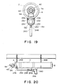
- the aforementioned discharge unit 154 is held, as shown in Figs. 12 and 19, so as to be gripped along the cartridge casing 2 by means of a pair of spring-like holders 230.
- a pair of fixing plates 232 are fixed at the lower portion of the casing 2 and extend in the axial direction of the casing 2, and the holders 230 are respectively fixed in mutually facing relation to the central portion of the corresponding fixing plate 232.
- the discharge unit 154 and the joint 130 are covered from below by a cover 234 of U-shaped cross section, and the end portion of this cover 234 on the front cap side of the cartridge casing 2 is rotatably mounted to the fixing plates 232 by means of a pair of pins 236.
- a plurality of slits 238 are formed near the other end portion of the cover 234. These slits 238 are arranged so as to correspond to a location of the fixing section 212 of aforementioned temperature sensor comprising the coil 222.
- the other end portion of the cover 234 is detachably coupled to a frame-like handle portion 240. That is, as shown in Fig. 12, an end wall 242 of cover 234 contacts the handle portion 240, and the end wall 242 and the handle portion 240 are latched by a connection pin 244.
- the connection pin 244 is urged in the direction of drawing out from the handle portion 240 by a compression coil spring. However, in the arrangement shown in Fig. 12, the displacement of the connection pin 244 is blocked by a lock lever 248 provided in the cover 234. Thus, when the lock lever 248 is unblocked, the connection pin 244 is drawn out of the handle portion 240 by the action of the urging force of the compression coil spring 246, and the latch between the cover 234 and the handle portion 240 is released.
- a sliding plate 252 is slidably mounted at the top of the handle portion 240 by means of two spacers 250.
- the head portions of each of the spacers 250 penetrate through slots in the sliding plate 252. These slots extend in the axial direction of the cartridge casing 2, such that the sliding plate 252 may be slid within a predetermined range in the direction toward and from the discharge unit 154.
- a tension coil spring 254 is mounted between the handle portion 240 and the end potion of the sliding plate 252 distal from the discharge unit 154.
- the handle portion 240 has a trigger 256 of which the central portion is rotatably supported on the handle portion 240 and the top end is rotatably coupled to the sliding plate 252.
- a protrusion 258 is formed on the lower surface of the sliding plate 252, and a hooking nail 260 is hooked to the protrusion 258.
- the hooking nail 260 is rotatably supported by cover plates 262 (see Fig. 1), which are mounted on the upper portion of the handle 240. As long as the hooking nail 260 is engaged to the protrusion 258, sliding of the sliding plate 252 toward the discharge unit 154 is blocked, that is, the operation of the trigger 256 is disabled. Furthermore, the engagement of the hooking nail 260 with the protrusion 258 can be released by actuating a releasing lever 264 connected to the hooking nail 260.
- An actuator arm 266 is fixed to the end portion of the sliding plate 252 which is positioned adjacent the discharge unit.
- the actuator arm 266 extends from the sliding plate 252 toward the discharge unit 154, and its front end is, as shown in Fig. 13, positioned so as to be close to the connector plate 208.
- the extinguishing apparatus can be kept, as shown in Fig. 20, hanging horizontally by means of suspending hooks 268 at an appropriate location in a house, a building, and the like. It is assumed that the slide 86 of the jet nozzle device 4 in the extinguishing apparatus is set in the switched positioned shown in Fig. 3 and the safety pin 220 of the discharge unit 154 is drawn away. Accordingly, as will be clear from Fig. 16, the slider ring 216 is allowed to move toward the closing cap 170 on the guide shaft 214, the slider ring 216 being held between the coil 222 made of the shape memory alloy and the two legs 186a of the retainer 186.
- the extinguishing apparatus of the invention thus set, should a fire break out, the discharge unit 154 becomes operational. That is, when the ambient air surrounding the extinguishing apparatus is heated by the fire, and the temperature of the coil 222 in the discharge unit 154 reaches over 70 ⁇ 5°C, coil 222 extends. As the plurality of slits 238 are formed on the cover 234 of the discharge unit 154, the heated ambient air can easily reach the coil 222 of the discharge unit through said slits 238. Accordingly, the response of the coil 222 to the outbreak of fire is enhanced, and the fire can be rapidly detected.
- the slider ring 216 is moved so as to be pushed into the relief hole 224 (refer to Fig. 16) of the closing cap 170 and the tapered portion 218 of the slider ring 216 pushes and opens the two legs 186a of the retainer, as shown by dot chain line in Fig. 14.
- the retainer 186 is pushed and opened, the two legs 186a of the retainer 186, which had been engaged with the annular groove 182a of the actuator rod 182 are released from the annular 182a, and the actuator rod 182 is thrust toward and strikes the mouth portion 174 of the high pressure bomb 172 due to the urging force of the compression coil spring 198.
- the hollow breaking needle 200 projects from the inner end surface of the actuator rod 182, this breaking needle pushes and breaks the seal 176 and enters into the interior of the mouth portion 174 of the high pressure bomb 172. Accordingly, the mouth portion 174 is opened and the high pressure fluid contained within the pressure bomb 172 flows out to the receiving chamber 204 of the compression coil spring 198 through the breaking needle 200 and the radial holes 202, and then flows into the interior of the unit casing 156 from the receiving chamber 204 through the communicating holes 206 of the supporting pipe 178. Thereafter, the high pressure fluid within the unit casing 156 flows into the interior of the cartridge casing 2 through the connector pipe 162 of the connector cap 160 and the joint 130.
- the extinguishing liquid is jetted downwardly from the downward jet nozzle 94.
- the extinguishing liquid is jetted from the forward jet nozzle 64. That is, in the latter case, the extinguishing liquid may flow from the rearward passage 56 to the forward passage 58 through the ports 60, the annular groove 92 and the ports 62, as will be clear from Fig. 4. Thereafter, the extinguishing liquid flows from this forward passage 58 to the front jet nozzle 64 and is then jetted from the jet hole 74 of the forward jet nozzle 64. Since the spray disc 78 is contained within the forward jet nozzle 64, as in the previous case, the extinguishing liquid jetted from the jet hole 74 of the front jet nozzle 64 assumes a conical shape of wide angle.
- the extinguishing apparatus of this invention detects heat due to a fire, and then can jet automatically the extinguishing liquid from either of the forward or downward jet nozzles 64, 94 of the jet nozzle device 42.
- the extinguishing liquid may be jetted from the jet nozzle device 42 by manual operation as well. That is, in the event a fire breaks out at a point distant from the place where the extinguishing apparatus is kept, the user may remove the extinguishing apparatus from the suspended hooks 268, and transport it to within operating proximity of the fire.
- the slide 86 of the jet nozzle device 42 of the extinguishing apparatus is preferably switched to the position of Fig. 4 and it is assumed that the coupling between the hooking nail 260 and the protrusion 258 shown in Fig. 12 has already been released by operation of the releasing lever 264 by the user.
- the user holds the front portion of the extinguishing apparatus with one hand and grasps the handle portion 240 with the other hand so as to direct the forward jet nozzle 64 toward the fire and then pulls the trigger 256 of the handle portion 240.
- the actuator arm 266 is advanced toward the discharge unit 154 by means of the sliding plate 252, as will be clear from Fig. 13, and presses the connector plate 208 of the discharge unit 154. Since the connector plate 208 is rotatable about pin 210 relative to the connector plate 188, the connector plate 208 is turned by the actuator arm 266, and made to move so as to push the slider ring 216 through the coil 222 toward the relief hole 224 of the closing cap 170. As a result, as in the foregoing examples the actuator rod 182 held back by the retainer 186 is released, whereby the extinguishing liquid is jetted from the forward jet nozzle 64 of the jet nozzle device 42.
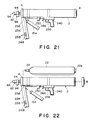
- a new cartridge 22 filled with extinguishing liquid is charged into the cartridge casing 2, and a new discharge unit 154 is coupled to the joint 130, whereby the re-use of the extinguishing apparatus becomes possible. That is, in order to remove the exhausted discharge unit 154, firstly, the cover 234 is opened as shown in Fig. 21, and the exhausted discharge unit 154 is taken out of the holders 230. This discharge unit 154 is then drawn out of the movable tube 140 of the joint, whereby it is released. As for the removal of the cartridge 22, first the rear cap 8 of the cartridge casing 2 is rotated and removed. The knob portion 22a of the cartridge 22 is then gripped by hand and drawn therefrom, whereby the cartridge 22 can be removed from the casing 2.
- a new discharge unit 154 and a new cartridge 22 can simply and rapidly be charged respectively by executing in reverse the aforementioned removal sequence steps.
Landscapes
- Health & Medical Sciences (AREA)
- Public Health (AREA)
- Business, Economics & Management (AREA)
- Emergency Management (AREA)
- Nozzles (AREA)
- Filling Or Discharging Of Gas Storage Vessels (AREA)
Abstract
Description
- The present invention relates to an extinguishing apparatus capable of detecting heat and automatically jetting an extinguishing material and also capable of jetting the extinguishing material manually.
- An extinguishing apparatus of this kind is disclosed in Japanese Provisional Patent Application No 61-37267 which has already been filed by an applicant of the present application. This known extinguishing apparatus is provided with a cartridge casing which is hollow cylindrical in shape and is open on its both ends. Both open ends of this casing are respectively closed by front and rear caps. A cartridge charged with extinguishing liquid is contained within the casing, and this cartridge is formed with tube having flexibility. Further, a screw-in type connector is provided at one end of this cartridge, and this connector protrudes to the outside through the front cap. A jet nozzle for extinguishing material is connected to the protruded end of the connector.
- Furthermore, a discharge unit containing a high pressure bomb is arranged to the exterior of the cartridge casing, and a conduit pipe extends from this discharge unit. An end of this conduit pipe is detachably coupled with the rear cap of the cartridge whereby it is connected with the interior of the casing. Incombustible high pressure fluid is charged in the pressure bomb, and the high pressure fluid within this pressure bomb is made either to be discharged manually or to be discharged automatically by detecting heat. Accordingly, when the high pressure fluid is discharged from the discharge unit, that is, from the pressure bomb, this high pressure fluid flows through the conduit pipe into the cartridge casing and acts to compress the cartridge. Consequently, the extinguishing liquid within this cartridge is pressed out of the cartridge and thereby projected from the jet nozzle.
- Moreover, in the aforementioned known extinguishing apparatus, after the extinguishing liquid within the cartridge is exhausted, not only the exhausted cartridge within the casing is replaced with a new cartridge, but the exhausted high pressure bomb, i.e., discharge unit is also replaced with a new discharge unit. However, the changing of the cartridge and high pressure bomb takes considerable effort and time, and in the case of known extinguishing apparatus, an inconvenience exists in that it cannot be rapidly reused. That is, as the cartridge is threadingly coupled with the jet nozzle through the connector passed through the front cap, and as the front cap is also fixed threadingly to the casing, in order to change the cartridge, the threaded coupling has to be respectively released between the connector and jet nozzle as well as between the front cap and casing, and thereafter the respective threaded couplings must be made over with the replacement cartridge and discharge unit.
- With respect to the changing of the discharge unit, it takes considerable effort to release and couple the conduit pipe from and to the rear cap. Furthermore, as aforementioned, in order to enable the discharging of high pressure fluid from the discharge unit by manual operation, the manual operating mechanism, comprising the trigger etc., and the discharge unit are mechanically coupled to one another, and therefore it is necessary to execute the releasing or coupling between the manual operating mechanism and discharge unit for the changing of the discharge unit.
- An object of the present invention is to provide, in an extinguishing apparatus of the above-described type, in which the changing of the cartridge of extinguishing material and the discharge unit containing the high pressure bomb can be rapidly executed and subsequent use of the apparatus is made possible.
- The above-described object is accomplished by the extinguishing apparatus of this invention, which comprises:
a hollow cartridge casing, said cartridge casing having a closed end and an open end;
a jet nozzle device mounted to the closed end of said cartridge casing,
said jet nozzle device including a discharge pipe extending into the cartridge casing by passing through the closed end of said cartridge casing in air tight manner from outside, and at least one jet nozzle mounted to a portion of the discharge pipe protruding from said cartridge casing;
a cartridge inserted into said cartridge casing from the open end thereof,
said cartridge including a flexible tube closed on both ends, fluid extinguishing material charged within the tube, a discharge outlet protruding from an end of the tube positioned on the side of said cartridge adjacent the discharge pipe when the cartridge is inserted into the interior of said cartridge casing, and sealing means for blocking the discharge outlet and for opening the discharge outlet when said cartridge is compressed by a predetermined force from the outside;
connecting means for coupling detachably the discharge outlet of said cartridge in plug-in manner to the discharge pipe of said jet nozzle as said cartridge is inserted to the interior of said cartridge casing;
a cap for closing the open end of said cartridge casing, detachably, threadingly mounted to the open end of said cartridge casing;
a joint pipe mounted to the external wall of said cartridge casing, one end of said joint pipe being open to the interior of said cartridge casing and the other end thereof being open to the exterior of said cartridge casing;
a discharge unit for discharging incombustible high pressure fluid through said joint pipe into said cartridge casing upon detection of a predetermined temperature,
said discharge unit including a hollow unit casing, joint means for detachably coupling said unit casing in plug-in manner to said joint pipe, a high pressure bomb contained within the unit casing, charged with high pressure fluid and having a closed outlet for discharging the high pressure fluid, and a heat responsive releasing means for opening the closed outlet of the high pressure bomb when the ambient temperature exceeds a predetermined temperature, the releasing means having a heat sensitive operational section exposed at the exterior of the unit casing;
holding means for detachably holding said discharge unit, connected with said joint pipe, to said cartridge casing; and
trigger means mounted separately from said discharge unit, and which may be actuated by the manual operation of the heat sensitive operational section of said releasing means regardless of temperature. - According to the above-described extinguishing apparatus, when either the ambient temperature exceeds a predetermined temperature, or said trigger means is operated manually, the releasing means is operated and the closed oulet of high pressure bomb is opened. Accordingly, incombustible high pressure fluid is discharged within the unit casing from the high pressure bomb, and the high pressure fluid is fed from the unit casing through said joint pipe into said cartridge casing. The pressure in said cartridge casing is thereby increased and said cartridge is compressed. Consequently, the discharge outlet of said cartridge is opened, and the extinguishing material flows out from said cartridge into said cartridge casing, and is thus supplied to said jet nozzle through the discharge pipe. As a result, the extinguishing material is delivered from said cartridge casing into the discharge pipe and projected from said jet nozzle.
- In the extinguishing apparatus of this invention, since the cartridge is coupled in plug-in manner to the discharged pipe by the connecting means, after the extinguishing material within the cartridge is exhausted, the exhausted cartridge can be simply drawn out of the cartridge casing after the cap of the cartridge casing is removed. Thereafter, a new cartridge can be connected to the discharge pipe by simply inserting the new cartridge into the cartridge casing, and the cartridge changing operation can be rapidly finished by remounting the cap to the cartridge casing.
- Furthermore, the discharge unit is also coupled in plug-in manner to the joint pipe by the joint means in a similar way to the cartridge, and the discharge unit and the trigger means are separated from one another, whereby the changing of the discharge unit can be rapidly done, once the high pressure fluid of high pressure bomb is exhausted.
- Therefore, the extinguishing apparatus of the present invention affords the rapid replacement of the cartridge and the discharge unit, which become expendable articles, and subsequent use of the extinguishing apparatus becomes possible by previously preparing a large number of such cartridges and discharge units.
- Other advantages of this invention will become clear from the following description of a preferred embodiment with reference to the accompanying drawings.
-
- Fig. 1 is a side view of an extinguishing apparatus according to a preferred embodiment of the present invention,
- Fig. 2 is a partially sectional side view of the extinguishing apparatus of Fig. 1,
- Fig. 3 is a cross sectional view of the jet nozzle device,
- Fig. 4 is cross sectional view of the jet nozzle in a second operational position,
- Fig. 5 is a plan view of spray disc contained within the forward jet nozzle,
- Fig. 6 is a cross sectional view taken along a line VI-VI in Fig. 5,
- Fig. 7 is a front view of jet disc of the downward jet nozzle,
- Fig. 8 is a cross sectional view taken along a line VIII-VIII in Fig. 7,
- Fig. 9 is a front view of the spray disc contained within the downward jet nozzle,
- Fig. 10 is a cross sectional view taken along a line X-X in Fig. 9,
- Fig. 11 is a rear view of the spray disc of Fig. 9,
- Fig. 12 is a cross sectional view showing a discharge unit and trigger,
- Fig. 13 is a detailed cross sectional view of the discharge unit,
- Fig. 14 is a plan view of a retainer,
- Fig. 15 is a perspective view of a pair of connector plates,
- Fig. 16 is a cross sectional view showing a coil arrangement made of a shape memory alloy, a slider ring and a retainer,
- Fig. 17 is a plan view of a safety pin,
- Fig. 18 shows an end surface of discharge unit,
- Fig. 19 is a front elevational view of extinguishing apparatus,
- Fig. 20 is a side view showing an operational position of the extinguishing apparatus, and
- Figs. 21 and 22 show the exchanging sequence of the cartridge and discharge unit.
- Referring to Fig. 1, an extinguishing apparatus according to a preferred embodiment of this invention is shown. This extinguishing apparatus is provided with a
cartridge casing 2, formed of a hollow cylinder open on both ends as shown in detail in Fig. 2. Afront cap 4 is coupled threadingly to an open end of thecartridge casing 2 located at the left side as seen in Fig. 2, and closes one open end of thecasing 2. Apacking 6 is sandwiched between thefront cap 4 and forward end of thecasing 2, and seals the gap between the thefront cap 4 and the open end in an airtight manner. Arear cap 8 is coupled threadingly to the other open end of thecasing 2, and closes the rear end of thecasing 2 in an airtight manner. Therear cap 8 comprises aninner cap 10 inserted into thecartridge casing 2, anouter cap 12 coupled threadingly to the other open end of thecasing 2, and a sealingmember 14 sandwiched between these inner andouter caps inner cap 10 and theouter cap 12 are coupled together by means of acoupling disc 16 and acoupling screw 18, and an O-ring seal 20 for sealing a gap between theinner cap 10 and the inner surface ofcasing 2 is mounted on the outer surface of theinner cap 10. - A
cartridge 22 charged with extinguishing liquid is contained within thecartridge casing 2. Thiscartridge 22 is made of flexible tube closed on both ends. Gaps are provided between thecartridge 22 and the inner surface of thecasing 2. Thecartridge 22 is supported by therear cap 8 as thecartridge 22 is inserted into the casing as shown in Fig. 2. - A
knob 22a protrudes from one end of thecartridge 22 located at the rear cap side, and adischarge head 24 for extinguishing liquid is provided on the other end located at the front cap side thereof. Thisdischarge head 24 has adischarge pipe 26 which is coaxial withcartridge 22 and protrudes from the interior ofcartridge 22 to the exterior in a liquidtight manner. A plurality ofopenings 28 are formed in the portion of thedischarge pipe 26, located within thecartridge 22, and an opening end of thedischarge pipe 26 protrudes from thecartridge 22 and is blocked by a sealingfilm 30. This sealingfilm 30 has sufficient strength so as not to be broken until thecartridge 22 is compressed by a predetermined pressure from the outside. - Furthermore, a
connector plug 32 is mounted on the protruding portion of thedischarge pipe 26. Thisconnector plug 32 has a tubular stepped shape having a large diameter portion into which the protruding portion of thedischarge pipe 26 is liquidtightly inserted. The small diameter portion of theconnector plug 32 extends to form an extension of thedischarge pipe 26, and an O-ring seal 34 is provided near the forward end of theconnector plug 32. - A connecting
pipe 36, in which is formed a discharge passage for the extinguishing liquid, is arranged within thecartridge casing 2 and cooperates with theconnector plug 32. This connectingpipe 36 is positioned coaxial with theconnector plug 32 and thedischarge pipe 26, and the end of the connectingpipe 36 located adjacent theconnector plug 32 is formed as asocket portion 38 for theconnector plug 32. That is, thesocket portion 38, is formed with a socket hole in which the small diameter portion of theconnector plug 32 can be inserted. This insertion is guided by the funnel-like open end of thesocket portion 38. The other end portion of the connectingpipe 36 is connected to thejet nozzle device 42 for extinguishing liquid by theinlet pipe 44 of thejet nozzle device 42. Theinlet pipe 44, as shown in Fig. 2, is formed of a tubular member of larger diameter than the connectingpipe 36, and passes through thefront cap 4 from the outside and thereby extends into thecasing 2. Aflange 46 is formed on the outer peripheral surface of theinlet pipe 44 and located within thecartridge casing 2. Further, a male threaded portion is formed on theinlet pipe 44 extending from theflange 46 toward the outside of thecasing 2. Accordingly, theinlet pipe 44 is fixed to thefront cap 4 by means of anut 48 screwed onto the male threaded portion. - The connecting
pipe 36 is connected to theinlet pipe 44 by insertion of the forward end portion of the connectingpipe 36 into theinlet pipe 44. An O-ring seal 50 is mounted on the forward end portion of the connectingpipe 36, and this connectingpipe 36 is secured with respect to theinlet pipe 44 by means of aset screw 52. - Referring to Figs. 3 and 4, details of aforementioned
jet nozzle device 42 are shown which will be hereinafter described. In theinlet pipe 44, apartitioning wall 54 is integrally formed at the interior of the front end portion protruding from thefront cap 4. Thepartitioning wall 54 partitions the interior of theinlet pipe 44 into arearward passage 56 communicating with theconnector plug 32 and aforward passage 58 of the front end side of theinlet pipe 44. - Furthermore, a plurality of
ports 60, close to thepartitioning wall 54 and communicating with therearward passage 56, and a plurality ofports 62, close to thepartitioning wall 54 and the communicating with theforward passage 58, are formed in the outer peripheral wall of theinlet pipe 44, respectively. - A
forward jet nozzle 64 is mounted on the front end of theinlet pipe 44 and is provided with inner andouter bodies small diameter portion 66a of theinner body 66 is screwed into the front end opening of theinlet pipe 44 and thelarge diameter portion 66b thereof is screwed into theouter body 68. O-ring seals 70 are disposed between theinner body 66 and theinlet pipe 44 as well as between the inner body and theouter body 68, respectively. - A
partitioning wall 72 is formed in the interior of theouter body 68, and ajet nozzle hole 74 is formed at the center of thispartitioning wall 72. Aspray disc 78 is disposed between the partitioningwall 72 and thelarge diameter portion 66b of theinner body 66. As shown in Figs. 5 and 6, thespray disc 78 is formed ofcircular plate 82 having a throughhole 80 at its center, and a plurality ofspray fins 84 disposed at equal intervals in the circumferential direction of thecircular plate 82 on the one side surface thereof abutting the surface of partitioningwall 72. Thesespray fins 84 are formed withsector plate pieces 84a and circular arcuate walls 34b formed integrally at circumferential edges of theseplate pieces 84a. - A
slide 86 is mounted on theinlet pipe 44 so as to cover theaforementioned ports slide 86 comprises a cylindrical, stepped member. Anannular groove 88, communicating with theports 60 when theslide 86 is located in the position shown in Fig. 3, is formed on the inner surface of thelarge diameter portion 86a of theslide 86. A pair of O-ring seals 90a located on either side of theports 60 are mounted on theinlet pipe 44, while an O-ring seal 90b is mounted within thesmall diameter portion 86b of theslide 86 near the forward end thereof. Furthermore, anannular groove 92 is also formed on the inner surface of thesmall diameter portion 86b. Theannular groove 92 has a predetermined width so that when thisannular groove 92 is in the position shown in Fig. 3, theports 62 communicate with the right end of theannular groove 92 and when theslide 86 is moved rightward as shown in Fig. 4, theports annular groove 92 respectively. Accordingly, as is shown in Fig. 4,ports annular groove 92, while the connection between theannular groove 88 and theports 60 is closed. - A
downward jet nozzle 94 is mounted on thelarge diameter portion 86a of theslide 86. That is, a threaded downwardly facingopening 96 is formed in the outer wall of thelarge diameter portion 86a so as to communicate with theannular groove 88. Thedownward jet nozzle 94 includes abody 98 of hollow, cylindrical shape. Thebody 98 is screwed into the threadedopening 96 through aseal 100. Thisbody 98 has a broader lower portion protruding from theside 86. Ajet disc 102 is screwed into the lower end opening of thebody 98. Thisjet disc 102 is ring shaped, having a recess at its center as shown in Figs. 7 and 8, and apartitioning wall 104 formed at the base of this recess. A generallyrectangular jet hole 106 is formed at the center of thispartitioning wall 104, and fourcircular holes 108 are formed around thejet hole 106 on thepartitioning wall 104. Further, an O-ring seal 110 is provided between thejet disc 102 and thebody 98, and aflange 112, larger in diameter than thebody 98 and abutting to the lower edge thereof is integrally formed at the outer end of thejet disc 102. - A
spray disc 116 is contained within thebody 98, so as to be sandwiched between thejet disc 102 and a spacer ring 114. Thisspray disc 116 has a throughhole 118 at its center as shown in detail in Figs. 9 to 11, and fourprotrusions 120 are integrally formed on the jet disc side of thespray disc 116, mutually independent from one another in the circumferential direction of thejet disc 116. Screw holes 122 are formed in theprotrusions 120 at positions corresponding to theholes 108 of thejet disc 102. Thespray disc 116 is coupled to thejet disc 102 by screwingscrews 124 into the screw holes 122 through theholes 108 of thejet disc 102. Furthermore, a plurality ofgrooves 126 extending generally in spiral from the throughhole 118 are provided on the other end surface of thespray disc 116. - A
feeding device 128 for feeding the high pressure fluid into the interior of thecasing 2 is mounted beneath thecartridge casing 2. Thisfeeding device 128 is provided with a joint 130 fixed to the front end portion of thecasing 2 as shown in detail in Fig. 12. This joint 130 has a fixedtube 132 of which one end protrudes in an airtight manner into the interior of thecasing 2, and another end extends downwardly. The fixedtube 126 comprises a stepped tubular member, the lower portion of which has an outer diameter slightly broader than the upper portion thereof and of which the top end is held by means of anut 134 to the inner wall of thecasing 2. Ahole 136 is provided in the lower end portion of the fixedtube 132, and a receivingseat 138 is mounted at the opening of thehole 136. The joint 130 further has amovable tube 140 of which one end portion is formed as aball 142. Theball 142 is fitted in thehole 136 and held between the receivingseat 138 and the inner surface of thehole 136 so as to be able to rotate. The other end of themovable tube 140 protrudes rearwardly through aslit 144 formed in the fixed tube, and is provided with an end portion serving as asocket 146. Theslit 144 extends generally vertically and defines the rotational direction of themovable tube 140. That is, themovable tube 140 may rotate only upwardly and downwardly. - The
internal passage 148 of themovable tube 140 turns upward within theball 142 and opens onto the outer surface of theball 142, whereby it communicates with theinternal passage 150 of the fixedtube 132. It will be noted that Fig. 2 shows only ahole 152 for inserting the fixedtube 132 into the interior of thecasing 2, the remaining elements of the joint being visible in Fig. 12. - A
discharge unit 154 of high pressure fluid is connected to the joint 130 by themovable tube 140. Thedischarge unit 154 has a hollowcylindrical unit casing 156 as shown in detail in Fig. 13, and one side opening end of theunit casing 156 is closed by aconnector cap 160 and packing 158, in airtight manner. Aconnector pipe 162 protrudes from the outer surface of theconnector cap 160 and is positioned coaxial with theunit casing 156. Theconnector pipe 162 can be detachably inserted into thesocket 146 of themovable tube 140, whereby theconnector pipe 162 communicates with the interior of theunit casing 156 through a throughhole 164 formed at the center of the packing 158 on one side, and communicates with the interior of thecartridge casing 2 through the joint 130 on the other side. An O-ring 166 is provided at the front end portion of theconnector pipe 162 affording the airtight coupling of the joint 130 and theconnector pipe 162. - A
closing cap 170 is coupled threadingly through packing 168 to the rearward end opening of theunit casing 156. - A
high pressure bomb 172 charged with incombustible high pressure fluid is contained within theunit casing 156. Themouth portion 174 of thehigh pressure bomb 172 is directed toward the closing cap and closed by a breakable seal 176. Themouth portion 174 of thehigh pressure bomb 172 is screwed into a supportingpipe 178. The supportingpipe 178 penetrates through the packing 168 and theclosing cap 170 in airtight manner. A flange portion 178a slightly larger in diameter is formed on the outer surface of the supportingpipe 178 located within theclosing cap 170. The flange portion 178a contacts a stepped face 170a provided on the inner surface of theclosing cap 170. Accordingly, the throughhole 164 of the packing 158 is never closed by thehigh pressure bomb 172 as the supportingtube 178 is situated sufficiently to the right as viewed in Fig. 13. - The internal passage of the supporting
pipe 178 is formed as a steppedhole 180, reduced in diameter at the end thereof remote from themouth portion 174 of thehigh pressure bomb 172, and anactuator rod 182 is slidably inserted into the small diameter portion of the steppedhole 180. One end portion of theactuator rod 182 protrudes from the supportingpipe 178, and this protruding end portion is held by aretainer 186. Theretainer 186 is made of a U-shaped spring member so that one end of the spring member is closed and the other end is open, the closed end portion being rotably mounted to theclosing cap 170. Aconnector plate 188 is disposed on the outer end surface of theclosing cap 170, and a hole affording passage of the portion of supportingtube 178 protruding from theclosing cap 170 is formed at the center of theconnector plate 188. A fixingbolt 190 is screwed into theclosing cap 170 through the closed end portion of theretainer 186 and theconnector plate 188, such that theretainer 186 is rotably mounted on the fixingbolt 190. Furthermore, bothlegs 186a of theretainer 186 extend so as to grip the protruding end portion of theactuator rod 182, and the center portion of bothlegs 186a is engaged with anannular groove 182a formed on the outer peripheral surface of the protruding end portion of theactuator rod 182 as shown in Fig. 14. - An O-
ring 194 is provided on the outer peripheral surface of theactuator rod 182 within the small diameter portion of the steppedhole 180 of the supportingpipe 178. The other end portion, that is the inner end of theactuator rod 182 extends into the large diameter portion of the steppedhole 180. Aflange 196 is integrally formed at the inner end of theactuator rod 182. Acompression coil spring 198 is disposed between theflange 196 and astep surface 180a dividing the small diameter portion and the large diameter portion within the steppedhole 180. Thecompression coil spring 198 constantly urges theactuator rod 182 toward thehigh pressure bomb 172. The extension stroke of thecompression coil spring 198 is selected larger than the distance between the inner end of theactuator rod 182 and themouth portion 174 ofhigh pressure bomb 172 as viewed in Fig. 13. - A breaking
needle 200 projects from the inner end surface of theactuator rod 182. The breakingneedle 200 is made of a tubular member having a tip end for breaking the seal 176 of thehigh pressure bomb 172 and an integral passage communicating with a radial hole 202 formed in theactuator rod 182. The radial hole 202 opens onto the outer peripheral surface of theactuator rod 182. That is, the radial hole 202 communicates with a receivingchamber 204 for thecompression coil spring 198 defined between theactuator rod 182 and the supportingpipe 178. - A plurality of communicating
holes 206 are formed in the peripheral wall of the supportingpipe 178 and located between themouth portion 174 ofhigh pressure bomb 172 and theactuator rod 182. These communicatingholes 206 are never closed by theflange 196 of theactuator rod 182, even when theactuator rod 182 abutts against themouth portion 174 of thehigh pressure bomb 172. In other words, the communicatingholes 206 are positioned at a larger distance from themouth portion 174 ofhigh pressure bottle 172, than the width of theflange 196. - The
aforementioned connector plate 188 has a pair ofsemi-circular bracket portions 188a integrally formed on either edge thereof and on the side thereof adjacent the fixing bolt. Theconnector plate 188 supports afixing section 212 for a temperature sensor by cooperating with afurther connector plate 208 having the same shape as theconnector plate 188.Connector plate 208 is disposedopposite connector plate 188 as will be clear from Fig. 15. A pair ofbracket portions 208a are superposed with thecorresponding bracket portions 188a of theconnector plate 188, and these sets of bracket portions are respectively interconnected by means of apin 210. Accordingly,connector plate 208 is rotatable around thepin 210 relative toconnector plate 188. - A
guide shaft 214 is provided on theclosing cap 170 diametrically opposite and spaced from the fixingbolt 190. Theguide shaft 214 has at one end portion thereof a threaded portion 214a which is screwed into theclosing cap 170. The other end portion of theguide shaft 214 extends through theconnector plate 188. Aslider ring 216 is slidably mounted on the latter portion of theguide shaft 214 so as to be located between theconnector plates slider ring 216 has a tapered portion 218 whose diameter tapers down toward theclosing cap 170, and the smaller diametric portion of this tapered portion 218 is clamped between the twolegs 186a of theretainer 186. In the arrangement shown in Figs. 13 and 16, asafety pin 220 as shown in Fig. 17 is arranged so as to clamp theguide shaft 214 between theconnector plate 188 and theslider ring 216. Thesafety pin 220 has the function of preventing theslider ring 216 from being moved unnecessarily toward the closing cap side. - A coil 222 made of a shape memory alloy is disposed between the
slider ring 216 and theconnector plate 208. This coil 222 has the property of, for example, extending when the ambient temperature reaches 70 ± 5°C. That is, the coil 222 serves not only as a temperature sensor, but also as an actuator for actuating theslider ring 216. - Furthermore, a
relief hole 224 for affording sufficient moving distance of theslider ring 216 is formed in theconnector plate 188 and theclosing cap 170 as shown in Fig. 16. As shown in Fig. 13, anannular groove 226 is formed on the outer peripheral surface of theclosing cap 170, and anattachment 228 for contacting with the front end of threaded portion 214a of theguide shaft 214 is fitted into theannular groove 226. Theattachment 228 is made of synthetic resin and has a circular arc shape as will be clear from Fig. 18. - The
aforementioned discharge unit 154 is held, as shown in Figs. 12 and 19, so as to be gripped along thecartridge casing 2 by means of a pair of spring-like holders 230. A pair of fixingplates 232 are fixed at the lower portion of thecasing 2 and extend in the axial direction of thecasing 2, and theholders 230 are respectively fixed in mutually facing relation to the central portion of the corresponding fixingplate 232. - Further, the
discharge unit 154 and the joint 130 are covered from below by acover 234 of U-shaped cross section, and the end portion of thiscover 234 on the front cap side of thecartridge casing 2 is rotatably mounted to the fixingplates 232 by means of a pair ofpins 236. A plurality ofslits 238 are formed near the other end portion of thecover 234. Theseslits 238 are arranged so as to correspond to a location of the fixingsection 212 of aforementioned temperature sensor comprising the coil 222. - The other end portion of the
cover 234 is detachably coupled to a frame-like handle portion 240. That is, as shown in Fig. 12, anend wall 242 ofcover 234 contacts thehandle portion 240, and theend wall 242 and thehandle portion 240 are latched by aconnection pin 244. Theconnection pin 244 is urged in the direction of drawing out from thehandle portion 240 by a compression coil spring. However, in the arrangement shown in Fig. 12, the displacement of theconnection pin 244 is blocked by alock lever 248 provided in thecover 234. Thus, when thelock lever 248 is unblocked, theconnection pin 244 is drawn out of thehandle portion 240 by the action of the urging force of thecompression coil spring 246, and the latch between thecover 234 and thehandle portion 240 is released. - A sliding
plate 252 is slidably mounted at the top of thehandle portion 240 by means of twospacers 250. The head portions of each of thespacers 250 penetrate through slots in the slidingplate 252. These slots extend in the axial direction of thecartridge casing 2, such that the slidingplate 252 may be slid within a predetermined range in the direction toward and from thedischarge unit 154. Atension coil spring 254 is mounted between thehandle portion 240 and the end potion of the slidingplate 252 distal from thedischarge unit 154. - The
handle portion 240 has atrigger 256 of which the central portion is rotatably supported on thehandle portion 240 and the top end is rotatably coupled to the slidingplate 252. Aprotrusion 258 is formed on the lower surface of the slidingplate 252, and a hookingnail 260 is hooked to theprotrusion 258. The hookingnail 260 is rotatably supported by cover plates 262 (see Fig. 1), which are mounted on the upper portion of thehandle 240. As long as the hookingnail 260 is engaged to theprotrusion 258, sliding of the slidingplate 252 toward thedischarge unit 154 is blocked, that is, the operation of thetrigger 256 is disabled. Furthermore, the engagement of the hookingnail 260 with theprotrusion 258 can be released by actuating a releasinglever 264 connected to the hookingnail 260. - An
actuator arm 266 is fixed to the end portion of the slidingplate 252 which is positioned adjacent the discharge unit. Theactuator arm 266 extends from the slidingplate 252 toward thedischarge unit 154, and its front end is, as shown in Fig. 13, positioned so as to be close to theconnector plate 208. - The operation of the extinguishing apparatus will now be described.
- The extinguishing apparatus can be kept, as shown in Fig. 20, hanging horizontally by means of suspending
hooks 268 at an appropriate location in a house, a building, and the like. It is assumed that theslide 86 of thejet nozzle device 4 in the extinguishing apparatus is set in the switched positioned shown in Fig. 3 and thesafety pin 220 of thedischarge unit 154 is drawn away. Accordingly, as will be clear from Fig. 16, theslider ring 216 is allowed to move toward theclosing cap 170 on theguide shaft 214, theslider ring 216 being held between the coil 222 made of the shape memory alloy and the twolegs 186a of theretainer 186. - The extinguishing apparatus of the invention thus set, should a fire break out, the
discharge unit 154 becomes operational. That is, when the ambient air surrounding the extinguishing apparatus is heated by the fire, and the temperature of the coil 222 in thedischarge unit 154 reaches over 70 ± 5°C, coil 222 extends. As the plurality ofslits 238 are formed on thecover 234 of thedischarge unit 154, the heated ambient air can easily reach the coil 222 of the discharge unit through said slits 238. Accordingly, the response of the coil 222 to the outbreak of fire is enhanced, and the fire can be rapidly detected. - Thus, when the coil extends due to the outbreak of a fire, the
slider ring 216 is moved so as to be pushed into the relief hole 224 (refer to Fig. 16) of theclosing cap 170 and the tapered portion 218 of theslider ring 216 pushes and opens the twolegs 186a of the retainer, as shown by dot chain line in Fig. 14. Thus, when theretainer 186 is pushed and opened, the twolegs 186a of theretainer 186, which had been engaged with theannular groove 182a of theactuator rod 182 are released from the annular 182a, and theactuator rod 182 is thrust toward and strikes themouth portion 174 of thehigh pressure bomb 172 due to the urging force of thecompression coil spring 198. Since thehollow breaking needle 200 projects from the inner end surface of theactuator rod 182, this breaking needle pushes and breaks the seal 176 and enters into the interior of themouth portion 174 of thehigh pressure bomb 172. Accordingly, themouth portion 174 is opened and the high pressure fluid contained within thepressure bomb 172 flows out to the receivingchamber 204 of thecompression coil spring 198 through the breakingneedle 200 and the radial holes 202, and then flows into the interior of the unit casing 156 from the receivingchamber 204 through the communicatingholes 206 of the supportingpipe 178. Thereafter, the high pressure fluid within theunit casing 156 flows into the interior of thecartridge casing 2 through theconnector pipe 162 of theconnector cap 160 and the joint 130. - Thus, when the high pressure fluid has flowed into the interior of the
casing 2, as will be clear from Fig. 2, the pressure in thecasing 2 is increased to a high level and thecartridge 22 charged with the extinguishing liquid is then compressed by such high pressure. As a result, the sealingfilm 30 of thecartridge 22 is broken, and the extinguishing liquid in thecartridge 22 flows out from theconnector plug 32 into therearward passage 56 of thejet nozzle device 42 through the connectingpipe 36. Since therearward passage 56 of theinlet pipe 44 is coupled to thedownward jet nozzle 94 through theport 60 and theannular groove 88 as shown in Fig. 3, the extinguishing liquid is jetted downwardly fromjet hole 106, passing through the interior of thedownward jet nozzle 94. As thespray disc 116 shown in Figs. 9 to 11 is contained within the interior of thedownward jet nozzle 94, the downward jet flow of the extinguishing liquid from thejet hole 106 assumes a conical shape of wide angle. - In the above described operating case, since the
slide 86 of thejet nozzle device 42 is set to the switched position shown in Fig. 3, the extinguishing liquid is jetted downwardly from thedownward jet nozzle 94. However, in the event theslide 86 is switched to the position shown in Fig. 4, the extinguishing liquid is jetted from theforward jet nozzle 64. That is, in the latter case, the extinguishing liquid may flow from therearward passage 56 to theforward passage 58 through theports 60, theannular groove 92 and theports 62, as will be clear from Fig. 4. Thereafter, the extinguishing liquid flows from thisforward passage 58 to thefront jet nozzle 64 and is then jetted from thejet hole 74 of theforward jet nozzle 64. Since thespray disc 78 is contained within theforward jet nozzle 64, as in the previous case, the extinguishing liquid jetted from thejet hole 74 of thefront jet nozzle 64 assumes a conical shape of wide angle. - The extinguishing apparatus of this invention, as aforementioned, detects heat due to a fire, and then can jet automatically the extinguishing liquid from either of the forward or
downward jet nozzles jet nozzle device 42. However, the extinguishing liquid may be jetted from thejet nozzle device 42 by manual operation as well. That is, in the event a fire breaks out at a point distant from the place where the extinguishing apparatus is kept, the user may remove the extinguishing apparatus from the suspended hooks 268, and transport it to within operating proximity of the fire. In such a case, theslide 86 of thejet nozzle device 42 of the extinguishing apparatus is preferably switched to the position of Fig. 4 and it is assumed that the coupling between the hookingnail 260 and theprotrusion 258 shown in Fig. 12 has already been released by operation of the releasinglever 264 by the user. - Thereafter, the user holds the front portion of the extinguishing apparatus with one hand and grasps the
handle portion 240 with the other hand so as to direct theforward jet nozzle 64 toward the fire and then pulls thetrigger 256 of thehandle portion 240. When thistrigger 256 is pulled, theactuator arm 266 is advanced toward thedischarge unit 154 by means of the slidingplate 252, as will be clear from Fig. 13, and presses theconnector plate 208 of thedischarge unit 154. Since theconnector plate 208 is rotatable aboutpin 210 relative to theconnector plate 188, theconnector plate 208 is turned by theactuator arm 266, and made to move so as to push theslider ring 216 through the coil 222 toward therelief hole 224 of theclosing cap 170. As a result, as in the foregoing examples theactuator rod 182 held back by theretainer 186 is released, whereby the extinguishing liquid is jetted from theforward jet nozzle 64 of thejet nozzle device 42. - After the extinguishing liquid contained within the
cartridge 22 is exhausted, anew cartridge 22 filled with extinguishing liquid is charged into thecartridge casing 2, and anew discharge unit 154 is coupled to the joint 130, whereby the re-use of the extinguishing apparatus becomes possible. That is, in order to remove theexhausted discharge unit 154, firstly, thecover 234 is opened as shown in Fig. 21, and theexhausted discharge unit 154 is taken out of theholders 230. Thisdischarge unit 154 is then drawn out of themovable tube 140 of the joint, whereby it is released. As for the removal of thecartridge 22, first therear cap 8 of thecartridge casing 2 is rotated and removed. Theknob portion 22a of thecartridge 22 is then gripped by hand and drawn therefrom, whereby thecartridge 22 can be removed from thecasing 2. - Thereafter, as will be clear from Fig. 22, a
new discharge unit 154 and anew cartridge 22 can simply and rapidly be charged respectively by executing in reverse the aforementioned removal sequence steps. - Therefore, according to the extinguishing apparatus of this invention, successive use of the extinguishing apparatus becomes possible by preparing beforehand
cartridges 22 anddischarge units 154 in large number.
Claims (8)
- Extinguishing apparatus comprising:
a cartridge casing,
a cartridge of extinguishing material contained within said cartridge casing,
a jet nozzle device which is mounted to said cartridge casing and coupled to said cartridge, and
discharge means for discharging the extinguishing material contained within said cartridge either automatically by detecting the ambient temperature or by manual operation,
characterized in that:
said cartridge casing (2) is hollow and includes a closed end, an open end and a cap (8) which is detachably threadingly fixed to the open end of said cartridge casing (2) and closes the open end of said cartridge casing (2);
said jet nozzle device (42) includes a discharge pipe (44) which penetrates in airtight manner through the closed end of said cartridge casing (2) from outside and extends into the interior of said cartridge casing (2), and at least one jet nozzle (64) fixed at the portion of the discharge pipe (44) protruding from said cartridge casing (2);
said cartridge (22) includes a flexible tube which is insertable from the open end of said cartridge casing (2) therein and of which both ends are closed, an extinguishing material having fluidity charged within the tube, a discharging outlet (24), protruding from the end portion of said cartridge (22) positioned at the discharge pipe side of said cartridge casing (2) when said cartridge (22) is inserted into said cartridge casing (2), and sealing means (30) which closes the discharge outlet (24) and opens the discharge outlet (24) when said cartridge (22) is compressed by a predetermined force from outside;
and in that said extinguishing apparatus further comprises:
coupling means (38) for detachably coupling the discharge outlet (24) of said cartridge (22) in plug-in manner to the discharge pipe (44) of said jet nozzle device (42) when said cartridge (22) is inserted into said cartridge casing (2); and
a joint pipe (130) which is fixed to the outer wall of said cartridge casing (2) and of which one end opens within said cartridge casing (2) and the other end is open to the outside of said cartridge casing (2);
said discharge means including a discharge unit (154) for discharging the incombustible high pressure fluid through said joint pipe (130) into said cartridge casing (2) when a sensor (222) has detected a predetermined temperature,
the discharge unit (154) comprising a hollow unit casing (156), joint means (162) for detachably coupling the unit casing (156) with said joint pipe (130), a high pressure bomb (172) which is contained within the unit casing (156) and in which a high pressure fluid is charged, the high pressure bomb (172) having a closed mouth portion (174) for discharging the high pressure fluid, and releasing means (212) of heat responsive type for opening the closed mouth portion (174) of the high pressure bomb (172) when the ambient temperature rises above a predetermined temperature, said releasing means (212) having a heat sensitive operating section (186,206,208,222) exposed to the outside of the unit casing (156); and
said discharge means further including holding means (230) for detachably holding the discharge unit (154) coupled with said joint pipe (130) to said cartridge casing (2), and trigger means (240,256,266) which is arranged separately from the discharge unit (154) and may be operated manually regardless of the temperature of the heat sensitive operating section (212) of the releasing means. - Extinguishing apparatus according to claim 1, characterized in that the jet nozzle (64) of said jet nozzle device (42) is threadingly fixed into the discharge pipe (44), and said jet nozzle device (42) further includes a second jet nozzle (94) which is different in jetting direction from the jetting direction of the first jet nozzle (64), and switching means (60,62,86,88,92) for selectively and manually coupling either one of the first and second jet nozzle (64,94) with the discharge pipe (44).
- Extinguishing apparatus according to claim 2, characterized in that the switching means comprises:
a partitioning wall (54) for partitioning the interior of the portion of the discharge pipe (44) protruding from said cartridge casing (2) into a forward passage (58) of a first jet nozzle side and a rearward passage (56) of a cartridge casing side,
a forward port (60) which is formed on the discharge pipe (44) and open to the forward passage (58),
a rearward port (62) which is formed on the discharge pipe (44) and open to the rearward passage (56),
a slide (86) which is located on the outside of said cartridge casing (2), said slide (86) being mounted on the discharged pipe (44) and coupled with the second jet nozzle (94),
a first annular groove (88) which is formed on the inner surface of the slide (86), said first annular groove (88) communicating with the rearward port (60) for the second jet nozzle (94) when the slide (86) is positioned in a first position in the axial direction of discharge pipe (44), and
a second annular groove (92) which is formed on the inner surface of the slide (86), said second annular groove (92) connecting the forward port (62) to the rearward port (60) when the slide (86) is positioned at a second position in the axial direction of the discharge pipe (44). - Extinguishing apparatus according to claim 3, characterized in that the first jet nozzle (64) is adapted to jet extinguishing material in a forward direction with respect to the discharge pipe (44), and the second jet nozzle (94) is adapted to jet extinguishing material in a sideward direction with respect to the discharge pipe (44).
- Extinguishing apparatus according to claim 1, characterized in that said connecting means includes a socket (38) formed at the end portion of the discharge pipe (44) positioned within said cartridge casing (2), and a connector plug (32) which is provided on the discharge outlet (24) of said cartridge (22) and adapted to be removably inserted into the socket (38) of the discharge pipe (44).
- Extinguishing apparatus according to claim 1, characterized in that the joint means includes a socket (146) provided at the distal end of the joint pipe (130), a connector pipe (162) provided on the unit casing (156) of said discharge unit (154) being adapted to be removably inserted in the socket (146).
- Extinguishing apparatus according to claim 1, characterized in that the releasing means of said discharge unit (154) includes:
an actuator rod (182) capable of thrust toward the closed outlet (174) of the high pressure bomb (172),
a breaking needle (200) provided on the actuator rod (182) and adapted to contact the closed outlet (174) and thereby break the closed outlet (174), and
a mechanism (182a,186) for blocking the thrust of the actuator rod (182). - Extinguishing apparatus according to claim 6, characterized in that the heat sensitive operating section includes a coil (222) made of a shape memory alloy which extends when heated over a predetermined temperature.
Priority Applications (1)
| Application Number | Priority Date | Filing Date | Title |
|---|---|---|---|
| DE69020721T DE69020721D1 (en) | 1990-04-12 | 1990-04-12 | Fire extinguishing system. |
Applications Claiming Priority (1)
| Application Number | Priority Date | Filing Date | Title |
|---|---|---|---|
| US07/497,895 US4972910A (en) | 1990-03-22 | 1990-03-22 | Extinguishing apparatus |
Publications (2)
| Publication Number | Publication Date |
|---|---|
| EP0451421A1 true EP0451421A1 (en) | 1991-10-16 |
| EP0451421B1 EP0451421B1 (en) | 1995-07-05 |
Family
ID=23978765
Family Applications (1)
| Application Number | Title | Priority Date | Filing Date |
|---|---|---|---|
| EP90401018A Expired - Lifetime EP0451421B1 (en) | 1990-03-22 | 1990-04-12 | Extinguishing apparatus |
Country Status (2)
| Country | Link |
|---|---|
| US (1) | US4972910A (en) |
| EP (1) | EP0451421B1 (en) |
Cited By (2)
| Publication number | Priority date | Publication date | Assignee | Title |
|---|---|---|---|---|
| EP0638334A1 (en) * | 1993-07-23 | 1995-02-15 | Glory Kiki Co. Ltd. | Repeating injector for fire extinguishing gas |
| EP0684053A1 (en) * | 1994-05-24 | 1995-11-29 | Katsutoshi Matsumoto | Fire extinguisher |
Families Citing this family (8)
| Publication number | Priority date | Publication date | Assignee | Title |
|---|---|---|---|---|
| JP2602239Y2 (en) * | 1993-06-22 | 2000-01-11 | グローリー機器株式会社 | Retainer operation mechanism of fire extinguishing gas automatic injection device |
| JPH07275388A (en) * | 1994-04-07 | 1995-10-24 | Glory Kiki Kk | Manually operated fire extinguisher |
| US5555940A (en) * | 1994-05-03 | 1996-09-17 | Glory Kiki Co., Ltd. | Automatic gas injection fire extinguisher |
| US5808541A (en) * | 1995-04-04 | 1998-09-15 | Golden; Patrick E. | Hazard detection, warning, and response system |
| US7188753B2 (en) * | 2004-04-20 | 2007-03-13 | Black & Decker Inc. | Pressure release connection and pneumatic dispensing device |
| KR101029554B1 (en) * | 2009-07-02 | 2011-04-18 | 강윤범 | Multifunctional Portable Fire Extinguisher System |
| US9604082B2 (en) * | 2014-12-18 | 2017-03-28 | Mpact Mpower, Llc. | Fore-grip handled fire-extinguisher |
| WO2025201549A1 (en) * | 2024-03-29 | 2025-10-02 | 上海永曜一合科技有限公司 | Fire extinguishing device |
Citations (2)
| Publication number | Priority date | Publication date | Assignee | Title |
|---|---|---|---|---|
| FR1216612A (en) * | 1957-12-16 | 1960-04-26 | Hand held fire extinguisher | |
| JPS6137267A (en) * | 1984-07-31 | 1986-02-22 | 藤木 優 | Automatic and manual fire extinguisher |
Family Cites Families (8)
| Publication number | Priority date | Publication date | Assignee | Title |
|---|---|---|---|---|
| US1634976A (en) * | 1924-01-25 | 1927-07-05 | Battle Fyre Company | Fire extinguisher |
| US1675232A (en) * | 1926-05-12 | 1928-06-26 | Straubhaar Albert | Fire extinguisher |
| US1988637A (en) * | 1933-02-01 | 1935-01-22 | Mccord Radiator & Mfg Co | Fire extinguisher |
| US2496160A (en) * | 1945-07-31 | 1950-01-31 | Cardox Corp | Hand fire extinguisher |
| US3005495A (en) * | 1957-12-16 | 1961-10-24 | Herberg Ernst | Hand fire extinguishers |
| US3802511A (en) * | 1972-12-06 | 1974-04-09 | L Good | Portable fire extinguisher |
| US4899826A (en) * | 1988-03-25 | 1990-02-13 | Penn William T | Combination fire extinguisher and tire sealer |
| JP3465195B2 (en) * | 1992-10-22 | 2003-11-10 | 株式会社日立製作所 | Cryopump |
-
1990
- 1990-03-22 US US07/497,895 patent/US4972910A/en not_active Expired - Fee Related
- 1990-04-12 EP EP90401018A patent/EP0451421B1/en not_active Expired - Lifetime
Patent Citations (2)
| Publication number | Priority date | Publication date | Assignee | Title |
|---|---|---|---|---|
| FR1216612A (en) * | 1957-12-16 | 1960-04-26 | Hand held fire extinguisher | |
| JPS6137267A (en) * | 1984-07-31 | 1986-02-22 | 藤木 優 | Automatic and manual fire extinguisher |
Cited By (3)
| Publication number | Priority date | Publication date | Assignee | Title |
|---|---|---|---|---|
| EP0638334A1 (en) * | 1993-07-23 | 1995-02-15 | Glory Kiki Co. Ltd. | Repeating injector for fire extinguishing gas |
| US5535829A (en) * | 1993-07-23 | 1996-07-16 | Glory Kiki Co., Ltd. | Repeating injector for fire extinguishing gas |
| EP0684053A1 (en) * | 1994-05-24 | 1995-11-29 | Katsutoshi Matsumoto | Fire extinguisher |
Also Published As
| Publication number | Publication date |
|---|---|
| US4972910A (en) | 1990-11-27 |
| EP0451421B1 (en) | 1995-07-05 |
Similar Documents
| Publication | Publication Date | Title |
|---|---|---|
| EP0451421B1 (en) | Extinguishing apparatus | |
| US4880143A (en) | Dispenser and components for high viscosity foam products | |
| US5088624A (en) | Attack-repellent device | |
| EP0218481B1 (en) | Inline dispersal valve | |
| BRPI0606694A2 (en) | cartridge for use with a distributor | |
| EP3797977B1 (en) | Anti-spray joint structure for connection of air nozzle of tire and connection hose of air compressor | |
| JPS61188086A (en) | Cartridge for skeleton stapler | |
| DK148973B (en) | SPRAY GUN FOR INJECTING MATERIAL IN A SPACE | |
| CA2161253A1 (en) | Paint ball gun | |
| GB2186059A (en) | Water fitting | |
| EP3797978B1 (en) | Anti-spray structure for connection of air nozzle of tire of vehicle and connection hose of air compressor | |
| US5076324A (en) | Quick disconnect coupling | |
| US4854388A (en) | Fire extinguishing apparatus | |
| EP0082950A2 (en) | Liquid supply device for an endoscope | |
| EP0081098B1 (en) | Endoscope | |
| WO1992006727A1 (en) | Disposable dispenser for powder | |
| KR920002462A (en) | Dilution instrument | |
| US2620038A (en) | Fire extinguisher | |
| US11603256B2 (en) | Device to spray omnidirectionally and avoid backflow | |
| US3632045A (en) | Portable fluid container | |
| JP2001340485A (en) | Differential pressure release valve and open sprinkler equipment | |
| KR960010507B1 (en) | Fire extinguishing | |
| US4583691A (en) | Spray gun and solvent cleaning of same | |
| JPH0661371B2 (en) | Fire extinguishing equipment with automatic and manual extinguishing cartridge replacement | |
| EP0238676A1 (en) | Drainage valve unit |
Legal Events
| Date | Code | Title | Description |
|---|---|---|---|
| PUAI | Public reference made under article 153(3) epc to a published international application that has entered the european phase |
Free format text: ORIGINAL CODE: 0009012 |
|
| AK | Designated contracting states |
Kind code of ref document: A1 Designated state(s): CH DE ES FR GB IT LI NL |
|
| 17P | Request for examination filed |
Effective date: 19920404 |
|
| 17Q | First examination report despatched |
Effective date: 19930826 |
|
| GRAA | (expected) grant |
Free format text: ORIGINAL CODE: 0009210 |
|
| AK | Designated contracting states |
Kind code of ref document: B1 Designated state(s): CH DE ES FR GB IT LI NL |
|
| PG25 | Lapsed in a contracting state [announced via postgrant information from national office to epo] |
Ref country code: IT Free format text: LAPSE BECAUSE OF FAILURE TO SUBMIT A TRANSLATION OF THE DESCRIPTION OR TO PAY THE FEE WITHIN THE PRE;WARNING: LAPSES OF ITALIAN PATENTS WITH EFFECTIVE DATE BEFORE 2007 MAY HAVE OCCURRED AT ANY TIME BEFORE 2007. THE CORRECT EFFECTIVE DATE MAY BE DIFFERENT FROM THE ONE RECORDED.SCRIBED TIME-LIMIT Effective date: 19950705 Ref country code: ES Free format text: THE PATENT HAS BEEN ANNULLED BY A DECISION OF A NATIONAL AUTHORITY Effective date: 19950705 Ref country code: FR Effective date: 19950705 Ref country code: NL Free format text: LAPSE BECAUSE OF FAILURE TO SUBMIT A TRANSLATION OF THE DESCRIPTION OR TO PAY THE FEE WITHIN THE PRESCRIBED TIME-LIMIT Effective date: 19950705 Ref country code: LI Effective date: 19950705 Ref country code: CH Effective date: 19950705 |
|
| REF | Corresponds to: |
Ref document number: 69020721 Country of ref document: DE Date of ref document: 19950810 |
|
| PG25 | Lapsed in a contracting state [announced via postgrant information from national office to epo] |
Ref country code: DE Effective date: 19951006 |
|
| REG | Reference to a national code |
Ref country code: CH Ref legal event code: PL |
|
| EN | Fr: translation not filed | ||
| NLV1 | Nl: lapsed or annulled due to failure to fulfill the requirements of art. 29p and 29m of the patents act | ||
| PLBE | No opposition filed within time limit |
Free format text: ORIGINAL CODE: 0009261 |
|
| STAA | Information on the status of an ep patent application or granted ep patent |
Free format text: STATUS: NO OPPOSITION FILED WITHIN TIME LIMIT |
|
| 26N | No opposition filed | ||
| PGFP | Annual fee paid to national office [announced via postgrant information from national office to epo] |
Ref country code: GB Payment date: 19960801 Year of fee payment: 7 |
|
| PG25 | Lapsed in a contracting state [announced via postgrant information from national office to epo] |
Ref country code: GB Effective date: 19970412 |
|
| GBPC | Gb: european patent ceased through non-payment of renewal fee |
Effective date: 19970412 |