EP0451444B1 - Valve for bottles of liquified petroleum gases - Google Patents
Valve for bottles of liquified petroleum gases Download PDFInfo
- Publication number
- EP0451444B1 EP0451444B1 EP91101071A EP91101071A EP0451444B1 EP 0451444 B1 EP0451444 B1 EP 0451444B1 EP 91101071 A EP91101071 A EP 91101071A EP 91101071 A EP91101071 A EP 91101071A EP 0451444 B1 EP0451444 B1 EP 0451444B1
- Authority
- EP
- European Patent Office
- Prior art keywords
- ram
- cylindrical
- valve
- mouth
- valve according
- Prior art date
- Legal status (The legal status is an assumption and is not a legal conclusion. Google has not performed a legal analysis and makes no representation as to the accuracy of the status listed.)
- Expired - Lifetime
Links
- 239000007789 gas Substances 0.000 title claims abstract description 38
- 239000003208 petroleum Substances 0.000 title claims abstract description 10
- 230000000295 complement effect Effects 0.000 claims description 3
- 238000004080 punching Methods 0.000 claims description 2
- 238000007519 figuring Methods 0.000 description 7
- 230000008901 benefit Effects 0.000 description 4
- 230000007246 mechanism Effects 0.000 description 2
- 238000000034 method Methods 0.000 description 2
- 230000008569 process Effects 0.000 description 2
- 230000002547 anomalous effect Effects 0.000 description 1
- 230000000740 bleeding effect Effects 0.000 description 1
- 239000001273 butane Substances 0.000 description 1
- 230000008859 change Effects 0.000 description 1
- 230000001419 dependent effect Effects 0.000 description 1
- 230000006872 improvement Effects 0.000 description 1
- 238000002347 injection Methods 0.000 description 1
- 239000007924 injection Substances 0.000 description 1
- 239000000463 material Substances 0.000 description 1
- IJDNQMDRQITEOD-UHFFFAOYSA-N n-butane Chemical compound CCCC IJDNQMDRQITEOD-UHFFFAOYSA-N 0.000 description 1
- OFBQJSOFQDEBGM-UHFFFAOYSA-N n-pentane Natural products CCCCC OFBQJSOFQDEBGM-UHFFFAOYSA-N 0.000 description 1
- 238000009527 percussion Methods 0.000 description 1
- 239000007787 solid Substances 0.000 description 1
Images

Classifications
-
- F—MECHANICAL ENGINEERING; LIGHTING; HEATING; WEAPONS; BLASTING
- F16—ENGINEERING ELEMENTS AND UNITS; GENERAL MEASURES FOR PRODUCING AND MAINTAINING EFFECTIVE FUNCTIONING OF MACHINES OR INSTALLATIONS; THERMAL INSULATION IN GENERAL
- F16K—VALVES; TAPS; COCKS; ACTUATING-FLOATS; DEVICES FOR VENTING OR AERATING
- F16K1/00—Lift valves or globe valves, i.e. cut-off apparatus with closure members having at least a component of their opening and closing motion perpendicular to the closing faces
- F16K1/30—Lift valves or globe valves, i.e. cut-off apparatus with closure members having at least a component of their opening and closing motion perpendicular to the closing faces specially adapted for pressure containers
- F16K1/304—Shut-off valves with additional means
- F16K1/306—Shut-off valves with additional means with a valve member, e.g. stem or shaft, passing through the seat
-
- F—MECHANICAL ENGINEERING; LIGHTING; HEATING; WEAPONS; BLASTING
- F16—ENGINEERING ELEMENTS AND UNITS; GENERAL MEASURES FOR PRODUCING AND MAINTAINING EFFECTIVE FUNCTIONING OF MACHINES OR INSTALLATIONS; THERMAL INSULATION IN GENERAL
- F16K—VALVES; TAPS; COCKS; ACTUATING-FLOATS; DEVICES FOR VENTING OR AERATING
- F16K1/00—Lift valves or globe valves, i.e. cut-off apparatus with closure members having at least a component of their opening and closing motion perpendicular to the closing faces
- F16K1/30—Lift valves or globe valves, i.e. cut-off apparatus with closure members having at least a component of their opening and closing motion perpendicular to the closing faces specially adapted for pressure containers
- F16K1/307—Additional means used in combination with the main valve
-
- F—MECHANICAL ENGINEERING; LIGHTING; HEATING; WEAPONS; BLASTING
- F17—STORING OR DISTRIBUTING GASES OR LIQUIDS
- F17C—VESSELS FOR CONTAINING OR STORING COMPRESSED, LIQUEFIED OR SOLIDIFIED GASES; FIXED-CAPACITY GAS-HOLDERS; FILLING VESSELS WITH, OR DISCHARGING FROM VESSELS, COMPRESSED, LIQUEFIED, OR SOLIDIFIED GASES
- F17C13/00—Details of vessels or of the filling or discharging of vessels
- F17C13/04—Arrangement or mounting of valves
-
- F—MECHANICAL ENGINEERING; LIGHTING; HEATING; WEAPONS; BLASTING
- F17—STORING OR DISTRIBUTING GASES OR LIQUIDS
- F17C—VESSELS FOR CONTAINING OR STORING COMPRESSED, LIQUEFIED OR SOLIDIFIED GASES; FIXED-CAPACITY GAS-HOLDERS; FILLING VESSELS WITH, OR DISCHARGING FROM VESSELS, COMPRESSED, LIQUEFIED, OR SOLIDIFIED GASES
- F17C2205/00—Vessel construction, in particular mounting arrangements, attachments or identifications means
- F17C2205/03—Fluid connections, filters, valves, closure means or other attachments
- F17C2205/0302—Fittings, valves, filters, or components in connection with the gas storage device
- F17C2205/0323—Valves
- F17C2205/0332—Safety valves or pressure relief valves
-
- F—MECHANICAL ENGINEERING; LIGHTING; HEATING; WEAPONS; BLASTING
- F17—STORING OR DISTRIBUTING GASES OR LIQUIDS
- F17C—VESSELS FOR CONTAINING OR STORING COMPRESSED, LIQUEFIED OR SOLIDIFIED GASES; FIXED-CAPACITY GAS-HOLDERS; FILLING VESSELS WITH, OR DISCHARGING FROM VESSELS, COMPRESSED, LIQUEFIED, OR SOLIDIFIED GASES
- F17C2205/00—Vessel construction, in particular mounting arrangements, attachments or identifications means
- F17C2205/03—Fluid connections, filters, valves, closure means or other attachments
- F17C2205/0302—Fittings, valves, filters, or components in connection with the gas storage device
- F17C2205/0338—Pressure regulators
-
- F—MECHANICAL ENGINEERING; LIGHTING; HEATING; WEAPONS; BLASTING
- F17—STORING OR DISTRIBUTING GASES OR LIQUIDS
- F17C—VESSELS FOR CONTAINING OR STORING COMPRESSED, LIQUEFIED OR SOLIDIFIED GASES; FIXED-CAPACITY GAS-HOLDERS; FILLING VESSELS WITH, OR DISCHARGING FROM VESSELS, COMPRESSED, LIQUEFIED, OR SOLIDIFIED GASES
- F17C2205/00—Vessel construction, in particular mounting arrangements, attachments or identifications means
- F17C2205/03—Fluid connections, filters, valves, closure means or other attachments
- F17C2205/0302—Fittings, valves, filters, or components in connection with the gas storage device
- F17C2205/0382—Constructional details of valves, regulators
- F17C2205/0385—Constructional details of valves, regulators in blocks or units
-
- F—MECHANICAL ENGINEERING; LIGHTING; HEATING; WEAPONS; BLASTING
- F17—STORING OR DISTRIBUTING GASES OR LIQUIDS
- F17C—VESSELS FOR CONTAINING OR STORING COMPRESSED, LIQUEFIED OR SOLIDIFIED GASES; FIXED-CAPACITY GAS-HOLDERS; FILLING VESSELS WITH, OR DISCHARGING FROM VESSELS, COMPRESSED, LIQUEFIED, OR SOLIDIFIED GASES
- F17C2221/00—Handled fluid, in particular type of fluid
- F17C2221/03—Mixtures
- F17C2221/032—Hydrocarbons
- F17C2221/035—Propane butane, e.g. LPG, GPL
-
- F—MECHANICAL ENGINEERING; LIGHTING; HEATING; WEAPONS; BLASTING
- F17—STORING OR DISTRIBUTING GASES OR LIQUIDS
- F17C—VESSELS FOR CONTAINING OR STORING COMPRESSED, LIQUEFIED OR SOLIDIFIED GASES; FIXED-CAPACITY GAS-HOLDERS; FILLING VESSELS WITH, OR DISCHARGING FROM VESSELS, COMPRESSED, LIQUEFIED, OR SOLIDIFIED GASES
- F17C2223/00—Handled fluid before transfer, i.e. state of fluid when stored in the vessel or before transfer from the vessel
- F17C2223/01—Handled fluid before transfer, i.e. state of fluid when stored in the vessel or before transfer from the vessel characterised by the phase
- F17C2223/0146—Two-phase
- F17C2223/0153—Liquefied gas, e.g. LPG, GPL
-
- F—MECHANICAL ENGINEERING; LIGHTING; HEATING; WEAPONS; BLASTING
- F17—STORING OR DISTRIBUTING GASES OR LIQUIDS
- F17C—VESSELS FOR CONTAINING OR STORING COMPRESSED, LIQUEFIED OR SOLIDIFIED GASES; FIXED-CAPACITY GAS-HOLDERS; FILLING VESSELS WITH, OR DISCHARGING FROM VESSELS, COMPRESSED, LIQUEFIED, OR SOLIDIFIED GASES
- F17C2223/00—Handled fluid before transfer, i.e. state of fluid when stored in the vessel or before transfer from the vessel
- F17C2223/03—Handled fluid before transfer, i.e. state of fluid when stored in the vessel or before transfer from the vessel characterised by the pressure level
- F17C2223/033—Small pressure, e.g. for liquefied gas
-
- F—MECHANICAL ENGINEERING; LIGHTING; HEATING; WEAPONS; BLASTING
- F17—STORING OR DISTRIBUTING GASES OR LIQUIDS
- F17C—VESSELS FOR CONTAINING OR STORING COMPRESSED, LIQUEFIED OR SOLIDIFIED GASES; FIXED-CAPACITY GAS-HOLDERS; FILLING VESSELS WITH, OR DISCHARGING FROM VESSELS, COMPRESSED, LIQUEFIED, OR SOLIDIFIED GASES
- F17C2260/00—Purposes of gas storage and gas handling
- F17C2260/02—Improving properties related to fluid or fluid transfer
- F17C2260/021—Avoiding over pressurising
-
- F—MECHANICAL ENGINEERING; LIGHTING; HEATING; WEAPONS; BLASTING
- F17—STORING OR DISTRIBUTING GASES OR LIQUIDS
- F17C—VESSELS FOR CONTAINING OR STORING COMPRESSED, LIQUEFIED OR SOLIDIFIED GASES; FIXED-CAPACITY GAS-HOLDERS; FILLING VESSELS WITH, OR DISCHARGING FROM VESSELS, COMPRESSED, LIQUEFIED, OR SOLIDIFIED GASES
- F17C2270/00—Applications
- F17C2270/07—Applications for household use
- F17C2270/0745—Gas bottles
Definitions
- This invention relates to a valve for bottles of liquified petroleum gases.
- valve for bottles of liquified petroleum gases shows a main advantage in relation to the old designs of valves which are collected and mentioned in the state of the art.
- valves known at present which are mounted in the mouths of the bottles for liquified petroleum gases, known as bottles for butane gas, show the same flow section for the supply than the section of exit of the gas. This exit section cannot be very large, as it would be desirable when bottling, if required to keep the pressure regulator within a reasonable size.
- CH-A-607646 discloses a valve assembly for bottles of liquified petroleum gases corresponding to the preamble of claim 1. Also this known valve assembly shows a flow section for the supply equal to that of the exit of the gas.
- the present invention provides a valve for bottles of liquified petroleum gases the shape of which is defined by a nearby cylindrical body having an upper section with a hollow cylindrical mouth inside which an opening is defined by a hollow cylindrical boss allowing the entrance to a nearly cylindrical inner space housing two rams one of them is external and approximately cylindrical and the other has two outercylindrical subsections and an intermediate prismatic body and further having a lower section, crowned by a fixing hex-nut having on one of its sides a safety valve lowerly followed by a truncated cone like subsection reversed with the revolution surface, threaded, a lower mouth allowing access to a wide cavity.
- a valve for bottles of liquified petroleum gases according to this invention shows the main advantage that nothing has been changed in the appearance of the valves, and these have the same configuration as those known, but some of its internal devices have been improved so to enable a gas admission flow at least twice. Therefore, we have an important lowering of the bottling time with the guarantee that the bottle will not show any leakages.
- a rubber ring or washer the function of which is adaptable tight locking.
- the outer vertex of the mouth is chamfered to facilitate the entrance of the regulator.
- a circular undercut is provided for the pressure mounting of the bearings shown on the mouth of the regulator. All these components are in the upper sub-body of the valve, while in its lower side, screwed to the upper one, another sub-body is shown crowned by a hex-nut which has in one of its sides a safety valve provided for allowing gas intermittent leakages when extreme dangerous environment conditions exist which cause the overpressure of the gas inside the bottles.
- An anomalous circumstance which would operate the safety valve can be that the place where the bottle is stocked reaches a very high temperature. This could cause an overpressure inside the bottle which could inflate and burst somewhere letting escape the gas.
- the safety valve operates, it makes that when inside the bottles the pressure precisely increases to 25 kg per square centimeter, this internal pressure overcomes the spring shown in the safety valve and let exhaust a quantity of gas which intermittently exits in a stream, until to loose the excess of internal pressure and recover the one that stabilizes the inside of the bottle.
- a reversed cylindrical hollow Inside, in the upper sub-body of the valve is a reversed cylindrical hollow, whose outer sides or external revolution surface create another cylindrical hollow between them and the external side of the valve, being these spaces for the flow of the liquified gas when going in and out of the bottle.
- This cylindrical ram has in its upper base a central cavity defined by a hollow cylinder projecting externally and internally and defining circular splines around them, in the bottom side, and internally, near to the lower mouth of this hollow cylindrical ram are cylindrical circular splines where a lock ring is attached with a central cylindrical punching.
- a central member in horizontal layout with quadrangular prismatic shape and chamfered apex, and that is crossed by a body or solid cylindrical rod, the ends of which project outside through holes existing in the upper base of the lower side of another cylindrical ram that receives it in its cavity.
- This inner ram can move up and down inside the cylindrical inner ram, following a fixed and set stroke.
- the operation of the valve is basically as follows:
- the obvious advantage is a higher gas supply through the aforesaid rams, with a first stage during which the first ram is operated and moved till the end of its stroke. So that during a second stage falls the second ram housing it, falling down, allowing a larger cavity twice higher than the one of the the known valves.
- the gas has basically when entering a first stage or position of the internal mechanisms of the valve where the gas enters with some difficulty in small quantities so that when acting a higher pressure, determines a higher stroke of all the device of the rams admission, and a higher heigth of the admission space, so that the mechanism has two admissions and the flow is clearly higher.
- the pressure of the gas in the bottle will keep the valve closed, as this is a self-locking valve.
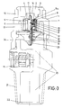
- Figures 1 and 2 shows the two rams determining the closing and the opening of the valve.
- the outer appearance of its revolution surface is shown in which prismatic ribs or bosses 6 are symmetrically located, allowing between them wide splines 5.
- the reference 12 indicates an intermediate prismatic body of the ram which is the actual closing member.
- the apex of this prismatic body is chamfered.
- the side view of the inner ram shows the lower cylindrical branch 23 located in the same shaft than the upper branch 11, both perpendicular to the intermediate prismatic body 12.
- the plan view of this ram shows its bottom surface and like around the vertical branch 11 is an annular ring 9 corresponding to a rubber ring that determines the seat and locking of the ram on the lower wall 10 of the central cylindrical mouth of the outer hollow cylindrical ram that houses it.
- the reference 2 indicates the hollow mouth of the valve.
- the reference 3 shows the profile of one of the inner bosses figuring in the valve mouth.
- the reference 4 indicates the inner hollow cylinder shown in the cavity 2 of the valve serving as entrance of the gas.
- the end branch 11 of one of the inner rams projects through it.
- the reference 16 indicates the rubber cylindrical ring figuring outside near to the mouth which is a member allowing the tightness with the regulator.
- the references 5 and 6 indicate the ribs and splines figuring at the outside of the cylindrical ram.
- the reference 17 indicates the outer wall and the wall inside which are the rams. The gas flows through the cavities of these rams.
- the reference 24 is a circular hollow provided for the mounting of the bearings of the regulator.
- the reference 15 is the side safety valve provided to remove the overpressure that could appear inside the bottle.
- the reference 21 indicates the threads of the valve for fixing the bottle.
- the reference 22 indicates the inner valve mouth which communicates with the bottle and the cavity 20 with the wide admission space, a cranked path and other small upper space communicating with the internal devices of the valve.
- the reference 15a indicates an inner cavity existing between the outer cylindrical ram and the hollow cylindrical mouth of the valve which is the length which will allow the flow of the gas after having lowered the double ram.
- the reference 7 indicates the opening or cylindrical mouth defined by a cylindrical wall 10.
- the reference 13 indicates a space or cavity inside the outer cylindrical ram allowing the flow of the gas after that the inner ram has travelled its descent stroke.
- the reference 9 indicates the rubber ring figuring embedded in the intermediate prismatic part 12 of the inner ram.
- the reference 18 indicates a lock ring limiting the stroke and independent descent of the inner ram with regard to the outer one.
- the references 19 and 29 indicate the springs which hold the rams pressed upwards and therefore the supply of the valves closed.
- the reference 23 indicates the lower branch of the preceding ram.
- the reference 13 indicates the inner cavity existing between the outer and inner rams 10 and 12.
Landscapes
- Engineering & Computer Science (AREA)
- General Engineering & Computer Science (AREA)
- Mechanical Engineering (AREA)
- Filling Or Discharging Of Gas Storage Vessels (AREA)
- Sampling And Sample Adjustment (AREA)
- Cookers (AREA)
- Devices For Use In Laboratory Experiments (AREA)
Applications Claiming Priority (2)
| Application Number | Priority Date | Filing Date | Title |
|---|---|---|---|
| ES19909001199U ES1013513Y (es) | 1990-04-10 | 1990-04-10 | Valvula para envases de gases licuados del petroleo perfeccionada. |
| ES9001199U | 1990-04-10 |
Publications (3)
| Publication Number | Publication Date |
|---|---|
| EP0451444A2 EP0451444A2 (en) | 1991-10-16 |
| EP0451444A3 EP0451444A3 (en) | 1992-02-26 |
| EP0451444B1 true EP0451444B1 (en) | 1996-07-10 |
Family
ID=8267079
Family Applications (1)
| Application Number | Title | Priority Date | Filing Date |
|---|---|---|---|
| EP91101071A Expired - Lifetime EP0451444B1 (en) | 1990-04-10 | 1991-01-28 | Valve for bottles of liquified petroleum gases |
Country Status (5)
| Country | Link |
|---|---|
| EP (1) | EP0451444B1 (da) |
| AT (1) | ATE140304T1 (da) |
| DE (1) | DE69120709T2 (da) |
| DK (1) | DK0451444T3 (da) |
| ES (1) | ES1013513Y (da) |
Families Citing this family (2)
| Publication number | Priority date | Publication date | Assignee | Title |
|---|---|---|---|---|
| ES2263326B1 (es) * | 2004-04-01 | 2007-11-01 | Repsol Butano, S.A. | Adaptador para acoplamiento a las valvulas de botellas de gases licuados del petroleo destinadas a automocion. |
| RU2629166C2 (ru) * | 2011-11-23 | 2017-08-24 | Микро Матик А/С | Система подачи давления |
Family Cites Families (6)
| Publication number | Priority date | Publication date | Assignee | Title |
|---|---|---|---|---|
| FR506639A (fr) * | 1918-11-18 | 1920-08-26 | Sulzer Ag | Organe obturateur pour fluides à haute pression |
| DE737483C (de) * | 1939-11-26 | 1943-07-15 | Forschungsanstalt Professor Ju | Zum gemeinsamen Versperren bzw. Eroeffnen zweier Durchlaesse an verfluessigtes Gas aufnehmenden Druckgefaessen dienendes, eingriffiges Doppelventil |
| FR1132374A (fr) * | 1955-03-24 | 1957-03-11 | Oxhydrique Francaise L | Robinet perfectionné |
| GB958111A (en) * | 1959-03-10 | 1964-05-13 | Sankey & Sons Ltd Joseph | Improvements in or relating to containers and closures therefor |
| JPS5120116A (en) * | 1974-08-09 | 1976-02-18 | Neriki Shokai Kk | Atsuryokuyokyono jidogyakushishiki shudoben |
| CH607646A5 (en) * | 1975-11-18 | 1978-09-29 | Liongas Ag | Valve unit on a container for liquid gas |
-
1990
- 1990-04-10 ES ES19909001199U patent/ES1013513Y/es not_active Expired - Lifetime
-
1991
- 1991-01-28 AT AT91101071T patent/ATE140304T1/de not_active IP Right Cessation
- 1991-01-28 DE DE69120709T patent/DE69120709T2/de not_active Expired - Fee Related
- 1991-01-28 EP EP91101071A patent/EP0451444B1/en not_active Expired - Lifetime
- 1991-01-28 DK DK91101071.8T patent/DK0451444T3/da active
Also Published As
| Publication number | Publication date |
|---|---|
| EP0451444A3 (en) | 1992-02-26 |
| DE69120709D1 (de) | 1996-08-14 |
| ATE140304T1 (de) | 1996-07-15 |
| DE69120709T2 (de) | 1997-02-27 |
| EP0451444A2 (en) | 1991-10-16 |
| ES1013513Y (es) | 1991-05-16 |
| DK0451444T3 (da) | 1996-08-12 |
| ES1013513U (es) | 1990-12-16 |
Similar Documents
| Publication | Publication Date | Title |
|---|---|---|
| US3789875A (en) | Fluid pressure actuated valve operator | |
| US5657790A (en) | Valves for pressurized containers | |
| US6419168B1 (en) | Metering head | |
| JPS6437361A (en) | Qunatity control pump for liquefied and/or low-viscosity substance | |
| EP1574450B1 (en) | Safety bottle cap | |
| RU2004126375A (ru) | Устройство, регулирующее давление в сосуде для распыления под давлением | |
| EP0451444A2 (en) | Valve for bottles of liquified petroleum gases | |
| KR20050070021A (ko) | 공기 유동 조절 장치 | |
| CN1044160A (zh) | 非提升式杆阀及更换永久密封装置方法 | |
| KR20070043929A (ko) | 액체 디스펜싱 밸브 | |
| BRPI0621871A2 (pt) | sistema para formação de fundo de lata | |
| KR100632932B1 (ko) | 거품 분출 펌프디스펜서 | |
| DE59307272D1 (de) | Zweikomponenten-Druckdose | |
| JPH0193676A (ja) | 安全制御弁 | |
| US4523515A (en) | Valve operating cylinder unit | |
| KR920006682B1 (ko) | 부착분입체 불락장치(付着紛粒體佛落裝置) | |
| US4142449A (en) | Hydraulic mine prop | |
| CA1162895A (en) | Slide valve for container of bulk material | |
| US7607490B2 (en) | Pneumatic impact tool and method | |
| CA2011964A1 (en) | Tilt valve cartridge | |
| CN222220102U (zh) | 一种可调节的出胶阀 | |
| KR20000055503A (ko) | 가스 스프링의 피스톤 조립체 | |
| JPH0814410A (ja) | ピストン弁 | |
| KR200261198Y1 (ko) | 에어모터 | |
| SU1736860A1 (ru) | Загрузочно-запорное устройство дл сыпучих материалов |
Legal Events
| Date | Code | Title | Description |
|---|---|---|---|
| PUAI | Public reference made under article 153(3) epc to a published international application that has entered the european phase |
Free format text: ORIGINAL CODE: 0009012 |
|
| AK | Designated contracting states |
Kind code of ref document: A2 Designated state(s): AT BE CH DE DK FR GB IT LI LU NL SE |
|
| PUAL | Search report despatched |
Free format text: ORIGINAL CODE: 0009013 |
|
| AK | Designated contracting states |
Kind code of ref document: A3 Designated state(s): AT BE CH DE DK FR GB IT LI LU NL SE |
|
| 17P | Request for examination filed |
Effective date: 19920825 |
|
| 17Q | First examination report despatched |
Effective date: 19941104 |
|
| GRAH | Despatch of communication of intention to grant a patent |
Free format text: ORIGINAL CODE: EPIDOS IGRA |
|
| GRAH | Despatch of communication of intention to grant a patent |
Free format text: ORIGINAL CODE: EPIDOS IGRA |
|
| ITF | It: translation for a ep patent filed | ||
| GRAA | (expected) grant |
Free format text: ORIGINAL CODE: 0009210 |
|
| AK | Designated contracting states |
Kind code of ref document: B1 Designated state(s): AT BE CH DE DK FR GB IT LI LU NL SE |
|
| REF | Corresponds to: |
Ref document number: 140304 Country of ref document: AT Date of ref document: 19960715 Kind code of ref document: T |
|
| REG | Reference to a national code |
Ref country code: DK Ref legal event code: T3 |
|
| REF | Corresponds to: |
Ref document number: 69120709 Country of ref document: DE Date of ref document: 19960814 |
|
| ET | Fr: translation filed | ||
| REG | Reference to a national code |
Ref country code: CH Ref legal event code: NV Representative=s name: BOVARD AG PATENTANWAELTE |
|
| PLBE | No opposition filed within time limit |
Free format text: ORIGINAL CODE: 0009261 |
|
| STAA | Information on the status of an ep patent application or granted ep patent |
Free format text: STATUS: NO OPPOSITION FILED WITHIN TIME LIMIT |
|
| 26N | No opposition filed | ||
| PGFP | Annual fee paid to national office [announced via postgrant information from national office to epo] |
Ref country code: FR Payment date: 20010111 Year of fee payment: 11 |
|
| PGFP | Annual fee paid to national office [announced via postgrant information from national office to epo] |
Ref country code: CH Payment date: 20010117 Year of fee payment: 11 |
|
| PGFP | Annual fee paid to national office [announced via postgrant information from national office to epo] |
Ref country code: BE Payment date: 20010119 Year of fee payment: 11 |
|
| PGFP | Annual fee paid to national office [announced via postgrant information from national office to epo] |
Ref country code: GB Payment date: 20010124 Year of fee payment: 11 |
|
| PGFP | Annual fee paid to national office [announced via postgrant information from national office to epo] |
Ref country code: AT Payment date: 20010125 Year of fee payment: 11 |
|
| PGFP | Annual fee paid to national office [announced via postgrant information from national office to epo] |
Ref country code: LU Payment date: 20010129 Year of fee payment: 11 |
|
| PGFP | Annual fee paid to national office [announced via postgrant information from national office to epo] |
Ref country code: DK Payment date: 20010130 Year of fee payment: 11 |
|
| PGFP | Annual fee paid to national office [announced via postgrant information from national office to epo] |
Ref country code: NL Payment date: 20010131 Year of fee payment: 11 |
|
| PGFP | Annual fee paid to national office [announced via postgrant information from national office to epo] |
Ref country code: SE Payment date: 20010205 Year of fee payment: 11 |
|
| PGFP | Annual fee paid to national office [announced via postgrant information from national office to epo] |
Ref country code: DE Payment date: 20010327 Year of fee payment: 11 |
|
| REG | Reference to a national code |
Ref country code: GB Ref legal event code: IF02 |
|
| PG25 | Lapsed in a contracting state [announced via postgrant information from national office to epo] |
Ref country code: LU Free format text: LAPSE BECAUSE OF NON-PAYMENT OF DUE FEES Effective date: 20020128 Ref country code: GB Free format text: LAPSE BECAUSE OF NON-PAYMENT OF DUE FEES Effective date: 20020128 Ref country code: AT Free format text: LAPSE BECAUSE OF NON-PAYMENT OF DUE FEES Effective date: 20020128 |
|
| PG25 | Lapsed in a contracting state [announced via postgrant information from national office to epo] |
Ref country code: SE Free format text: LAPSE BECAUSE OF NON-PAYMENT OF DUE FEES Effective date: 20020129 |
|
| PG25 | Lapsed in a contracting state [announced via postgrant information from national office to epo] |
Ref country code: LI Free format text: LAPSE BECAUSE OF NON-PAYMENT OF DUE FEES Effective date: 20020131 Ref country code: DK Free format text: LAPSE BECAUSE OF NON-PAYMENT OF DUE FEES Effective date: 20020131 Ref country code: CH Free format text: LAPSE BECAUSE OF NON-PAYMENT OF DUE FEES Effective date: 20020131 Ref country code: BE Free format text: LAPSE BECAUSE OF NON-PAYMENT OF DUE FEES Effective date: 20020131 |
|
| BERE | Be: lapsed |
Owner name: S.A. REPSOL-BUTANO Effective date: 20020131 |
|
| PG25 | Lapsed in a contracting state [announced via postgrant information from national office to epo] |
Ref country code: NL Free format text: LAPSE BECAUSE OF NON-PAYMENT OF DUE FEES Effective date: 20020801 Ref country code: DE Free format text: LAPSE BECAUSE OF NON-PAYMENT OF DUE FEES Effective date: 20020801 |
|
| EUG | Se: european patent has lapsed |
Ref document number: 91101071.8 |
|
| REG | Reference to a national code |
Ref country code: CH Ref legal event code: PL |
|
| GBPC | Gb: european patent ceased through non-payment of renewal fee |
Effective date: 20020128 |
|
| PG25 | Lapsed in a contracting state [announced via postgrant information from national office to epo] |
Ref country code: FR Free format text: LAPSE BECAUSE OF NON-PAYMENT OF DUE FEES Effective date: 20020930 |
|
| NLV4 | Nl: lapsed or anulled due to non-payment of the annual fee |
Effective date: 20020801 |
|
| REG | Reference to a national code |
Ref country code: DK Ref legal event code: EBP |
|
| REG | Reference to a national code |
Ref country code: FR Ref legal event code: ST |
|
| PG25 | Lapsed in a contracting state [announced via postgrant information from national office to epo] |
Ref country code: IT Free format text: LAPSE BECAUSE OF NON-PAYMENT OF DUE FEES;WARNING: LAPSES OF ITALIAN PATENTS WITH EFFECTIVE DATE BEFORE 2007 MAY HAVE OCCURRED AT ANY TIME BEFORE 2007. THE CORRECT EFFECTIVE DATE MAY BE DIFFERENT FROM THE ONE RECORDED. Effective date: 20050128 |