EP0451464A2 - Méthode et circuit de réglage du courant de soudage, la puissance de soudage en fonction de la vitesse de soudage - Google Patents
Méthode et circuit de réglage du courant de soudage, la puissance de soudage en fonction de la vitesse de soudage Download PDFInfo
- Publication number
- EP0451464A2 EP0451464A2 EP91102241A EP91102241A EP0451464A2 EP 0451464 A2 EP0451464 A2 EP 0451464A2 EP 91102241 A EP91102241 A EP 91102241A EP 91102241 A EP91102241 A EP 91102241A EP 0451464 A2 EP0451464 A2 EP 0451464A2
- Authority
- EP
- European Patent Office
- Prior art keywords
- welding
- actuator
- circuit arrangement
- current
- controller
- Prior art date
- Legal status (The legal status is an assumption and is not a legal conclusion. Google has not performed a legal analysis and makes no representation as to the accuracy of the status listed.)
- Granted
Links
- 238000003466 welding Methods 0.000 title claims abstract description 94
- 238000000034 method Methods 0.000 title claims description 8
- 230000001419 dependent effect Effects 0.000 claims abstract description 18
- 239000002184 metal Substances 0.000 claims description 6
- 229910052751 metal Inorganic materials 0.000 claims description 6
- 230000001105 regulatory effect Effects 0.000 claims description 3
- 238000004021 metal welding Methods 0.000 abstract description 2
- 238000004519 manufacturing process Methods 0.000 description 4
- 238000010586 diagram Methods 0.000 description 2
- 150000002739 metals Chemical class 0.000 description 2
- 230000006978 adaptation Effects 0.000 description 1
- 239000000654 additive Substances 0.000 description 1
- 230000000996 additive effect Effects 0.000 description 1
- 239000002826 coolant Substances 0.000 description 1
- 238000001816 cooling Methods 0.000 description 1
- 230000000694 effects Effects 0.000 description 1
- 238000002955 isolation Methods 0.000 description 1
- 238000011144 upstream manufacturing Methods 0.000 description 1
- XLYOFNOQVPJJNP-UHFFFAOYSA-N water Substances O XLYOFNOQVPJJNP-UHFFFAOYSA-N 0.000 description 1
- 238000004804 winding Methods 0.000 description 1
Images


Classifications
-
- B—PERFORMING OPERATIONS; TRANSPORTING
- B23—MACHINE TOOLS; METAL-WORKING NOT OTHERWISE PROVIDED FOR
- B23K—SOLDERING OR UNSOLDERING; WELDING; CLADDING OR PLATING BY SOLDERING OR WELDING; CUTTING BY APPLYING HEAT LOCALLY, e.g. FLAME CUTTING; WORKING BY LASER BEAM
- B23K9/00—Arc welding or cutting
- B23K9/095—Monitoring or automatic control of welding parameters
- B23K9/0956—Monitoring or automatic control of welding parameters using sensing means, e.g. optical
-
- B—PERFORMING OPERATIONS; TRANSPORTING
- B23—MACHINE TOOLS; METAL-WORKING NOT OTHERWISE PROVIDED FOR
- B23K—SOLDERING OR UNSOLDERING; WELDING; CLADDING OR PLATING BY SOLDERING OR WELDING; CUTTING BY APPLYING HEAT LOCALLY, e.g. FLAME CUTTING; WORKING BY LASER BEAM
- B23K26/00—Working by laser beam, e.g. welding, cutting or boring
- B23K26/20—Bonding
- B23K26/21—Bonding by welding
- B23K26/24—Seam welding
- B23K26/26—Seam welding of rectilinear seams
- B23K26/262—Seam welding of rectilinear seams of longitudinal seams of tubes
-
- B—PERFORMING OPERATIONS; TRANSPORTING
- B23—MACHINE TOOLS; METAL-WORKING NOT OTHERWISE PROVIDED FOR
- B23K—SOLDERING OR UNSOLDERING; WELDING; CLADDING OR PLATING BY SOLDERING OR WELDING; CUTTING BY APPLYING HEAT LOCALLY, e.g. FLAME CUTTING; WORKING BY LASER BEAM
- B23K9/00—Arc welding or cutting
- B23K9/06—Arrangements or circuits for starting the arc, e.g. by generating ignition voltage, or for stabilising the arc
- B23K9/073—Stabilising the arc
Definitions
- the present invention relates to a method and a circuit arrangement for regulating the welding current or the welding power as a function of the welding speed in welding devices for continuous longitudinal seam welding to metal tubes formed into a tube.
- a circuit arrangement (DE-OS 19 00 856) is already known, in which the electrodes of a welding device are influenced from a voltage source via a transformer, an actuator adjusting the welding current and a speed-dependent tachometer generator. Means are provided for regulating the level of the welding current as a function of the supply voltage, the electrode spacing and as a function of the supply voltage, the electrode spacing and as a function of temperature fluctuations.
- the actual welding current value is measured continuously and the actuator is influenced by means of a feedforward control with even the slightest fluctuations, so that the welding current intensity corresponds to the given requirements.
- the control can be carried out at short notice, so that fluctuations in the supply voltage, the electrode spacing or temperature changes with respect to the Do not make the welding current noticeable, but the welding current strength always receives the value that is required for welding through the weld seam.
- the invention is therefore based on the object of bringing about a welding current control or a regulation of the welding power when it comes to a laser welding device as a function of the production speed, which ensures problem-free welding of any metals and metal strips of different strip thicknesses with an optimal welding current shape.
- a speed-dependent voltage value is added to an adjustable fixed voltage value.
- Setting a fixed tension value for example depending on the selected strip thickness, causes one Zero point shift in the current-speed diagram, while the addition of the speed-dependent voltage value leads to the welding current or welding load characteristic curve beginning at the respective zero point. This measure enables the selection of any current or power values depending on the welding speed, the adaptation to any welding conditions is possible.
- a circuit arrangement has proven to be expedient in the case of a direct-current arc welding device in which the welding electrodes are fed from a voltage source via a transformer, an actuator which adjusts the welding current and rectifier elements, and the actuator is influenced by a speed-dependent tachometer generator which is connected to a controller.
- a speed-dependent tachometer generator which is connected to a controller.
- an adjustable fixed voltage source is connected in series with the tachometer generator.
- the tachometer generator provides the speed-dependent voltage of z. B. 0-20 V
- the adjustable fixed voltage source such as any step switch, provides a base voltage value of 0-10 V.
- the voltage values added in a corresponding circuit are then fed to one input of a welding current regulator, while the actual welding current value coming from the current transformer is input at the other input.
- a target / actual value comparison in the welding current controller then leads to the required welding current at the output.
- the welding electrodes from a voltage source via a transformer, the one Actuator setting welding current and rectifier elements are fed, the actuator being influenced by a welding speed-dependent tachometer generator which is connected to a controller.
- the tachogenerator and a fixed voltage source are connected with their outputs separately to the inputs of a summing amplifier, the output of which acts on an input of the welding current regulator, while a further input of this regulator is connected to the direct current converter.
- a further improvement in the welding current control is ensured in that a voltage divider is provided between the output of the tachometer generator and the input of the summing amplifier. With its help, the inclination of the welding current characteristic can be adjusted.
- the object of the invention by reducing the ripple of the welding current, optimal conditions for welding metal strips formed into tubes
- a welding current control in which the welding electrodes are fed from a voltage source via a transformer, an actuator adjusting the welding current and rectifier elements and the actuator is influenced by a welding speed-dependent tachometer generator, which is connected to a controller, to the measure that the actuator is a thyristor rectifier arrangement, which is controlled via a downstream transistor unit controlled by the controller.
- the advantage of short control times, which result from the use of the transistors, is used when applying the invention.
- the thyristor rectifier arrangement is controlled in such a way that the voltage drop across the transistors and the consequent loss line are kept to a minimum.
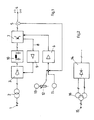
- 1 denotes the supply voltage source, which can be, for example, the 50 Hz AC network.
- the transformer 2 is connected to the voltage source 1 and is connected to the thyristor 3 on the secondary side.
- a DC converter 5 is connected between the electrodes (4) of the welding device (not shown) and the thyristor 3 (+) and (-), from which a voltage corresponding to the actual value of the welding current can be tapped on the secondary side.
- the controller 6 receives its energy supply via a power pack, not shown.
- the thyristor rectifier arrangement 3 is again impermeable to current at each zero crossing of the voltage and must then be fired again in each case.
- This ignition takes place by the controller 6, which sets the time of ignition of the thyristor 3 sooner or later depending on the circumstances, so that correspondingly more or less current reaches the welding electrodes 4.
- This control of the thyristor unit 3 by the controller 6 does not take place directly, but, as shown, via the transistor unit 7, which is connected downstream of the thyristor rectifier arrangement 3 but has a feedback 8 to it, with the aid of which the thyristor arrangement 3 is connected via a control amplifier 9 is controlled so that the voltage drop across the transistors 7 and thus their power loss can be kept to a minimum.
- the controllability is further improved and there is a substantial reduction in the ripple of the welding current even at high take-off speeds reached.
- a further improvement can be achieved in that, as can be seen from FIG. 1, a filter element 10 is arranged between the thyristor rectifier arrangement 3 and the downstream transistor unit 7.
- the regulator 6 is acted upon by a voltage which is composed of an adjustable fixed voltage value and a speed-dependent voltage value.
- an additive circuit comprising the tachometer generator 11 and a voltage source 13 which can be set via the resistor 12 is provided.
- the voltage value resulting from the switching elements 11 and 13 is passed to the controller 6, which is connected to the DC converter 5 and receives the actual DC value from there, which is then compared with the voltage value supplied by the tachometer generator 11 and the adjustable voltage source 13 and for regulation is used.
- FIG. 2 Deviating from the embodiment shown in FIG. 1, an arrangement is shown in FIG. 2, in which the z. B. six-pulse thyristor rectifier arrangement 3 is replaced by a twelve-pulse arrangement 14. Accordingly, the transformer 16 fed by the supply voltage source 15 is also equipped with a second secondary winding. All other switching elements of the circuit arrangement according to the invention correspond to those as have been used in FIG. 1 for carrying out the invention.
- 21 denotes the supply voltage source, which is, for example, the 50 Hz AC network connected, which is connected to the thyristor 23 on the secondary side.
- a direct current converter 25 is connected between the electrodes (24) of the welding device and the thyristor (23), from which a voltage corresponding to the actual value of the welding current can be tapped on the secondary side.
- the controller 26 receives its energy supply from the power supply unit 27. As already mentioned above, the thyristor 23 becomes impermeable to current at each zero crossing of the voltage and must then be fired again. This ignition is carried out by the controller 26, which sooner or later sets the time of the ignition of the thyristor 23 depending on the circumstances, so that correspondingly more or less current reaches the welding electrodes 24.
- the controller 26, in whose place the input of a laser can also take place, is subjected to a voltage which results from an adjustable fixed voltage value and a speed-dependent voltage value.
- an addition circuit comprising the tachometer generator 28 and the adjustable voltage source 29 is provided.
- the voltage value determined from 28 and 29 is passed to the controller 26, which is connected to the direct current converter 25 and receives the actual welding current value from there, which is then compared with the voltage value supplied by the tachometer generator 28 and the adjustable voltage source 29 and used for regulation .
- the DC converter 25 can also be formed by a shunt with a downstream isolation amplifier.
- a summing amplifier 30 of a commercially available type is used to add the two voltage values.
- the output of a summing amplifier is with the becomes.
- the output of a summing amplifier is connected to one input of the controller 26 or to the input z.
- B. a controllable high-frequency generator that controls the output power of a welding laser while the other input is connected to the current transformer 25.
- the fixed voltage value required for the addition is supplied from the adjustable voltage source 31 to the one input of the summing amplifier 30, the respective voltage value being set by the voltage divider 32.
- the speed-dependent value is supplied by the tachometer generator 33, the steepness of the speed-dependent characteristic curve being adjustable by the step switch 34.
- FIG. 5 The operation of the circuits described in FIGS. 3 and 4 is shown in FIG. 5 in a diagram.
- the welding current in A is plotted against the welding speed in m / min.
- the permanently adjustable voltage value supplied to the summing amplifier 30 leads to a certain base current, a change in this voltage value leads, as can be seen from the figure, to a parallel shift of the zero point in the direction of the current axis or to a corresponding parallel shift of the curve family C. It is essential for the invention further that the inclination of the family of curves 30 can be changed by the step switch 34 connected upstream of the tachometer generator 33, so that depending on the requirements, depending on the welding speed, it is possible to run with smaller or larger welding current strengths per unit of time.
Landscapes
- Engineering & Computer Science (AREA)
- Physics & Mathematics (AREA)
- Plasma & Fusion (AREA)
- Mechanical Engineering (AREA)
- Optics & Photonics (AREA)
- Arc Welding Control (AREA)
- Generation Of Surge Voltage And Current (AREA)
- Lining Or Joining Of Plastics Or The Like (AREA)
- Resistance Welding (AREA)
- Butt Welding And Welding Of Specific Article (AREA)
- Laser Beam Processing (AREA)
- Dc-Dc Converters (AREA)
Applications Claiming Priority (4)
| Application Number | Priority Date | Filing Date | Title |
|---|---|---|---|
| DE4011647 | 1990-04-11 | ||
| DE4011647A DE4011647A1 (de) | 1990-04-11 | 1990-04-11 | Verfahren zur regelung des schweissstromes in abhaengigkeit von der schweissgeschwindigkeit bei lichtbogenschweisseinrichtungen |
| DE4014275 | 1990-05-04 | ||
| DE4014275A DE4014275A1 (de) | 1990-05-04 | 1990-05-04 | Schaltungsanordnung zur regelung des schweissstromes in abhaengigkeit von der schweissgeschwindigkeit |
Publications (3)
| Publication Number | Publication Date |
|---|---|
| EP0451464A2 true EP0451464A2 (fr) | 1991-10-16 |
| EP0451464A3 EP0451464A3 (en) | 1992-10-07 |
| EP0451464B1 EP0451464B1 (fr) | 1996-06-12 |
Family
ID=25892090
Family Applications (1)
| Application Number | Title | Priority Date | Filing Date |
|---|---|---|---|
| EP91102241A Expired - Lifetime EP0451464B1 (fr) | 1990-04-11 | 1991-02-18 | Méthode et circuit de réglage du courant de soudage, la puissance de soudage en fonction de la vitesse de soudage |
Country Status (15)
| Country | Link |
|---|---|
| US (1) | US5192850A (fr) |
| EP (1) | EP0451464B1 (fr) |
| JP (1) | JP3091509B2 (fr) |
| KR (1) | KR0180021B1 (fr) |
| CN (1) | CN1031929C (fr) |
| AT (1) | ATE139160T1 (fr) |
| AU (1) | AU643984B2 (fr) |
| CA (1) | CA2040132C (fr) |
| DE (1) | DE59107913D1 (fr) |
| DK (1) | DK0451464T3 (fr) |
| ES (1) | ES2090153T3 (fr) |
| FI (1) | FI98711C (fr) |
| GR (1) | GR3020309T3 (fr) |
| NO (1) | NO300920B1 (fr) |
| RU (1) | RU2028203C1 (fr) |
Cited By (1)
| Publication number | Priority date | Publication date | Assignee | Title |
|---|---|---|---|---|
| EP0570678A1 (fr) * | 1992-05-20 | 1993-11-24 | kabelmetal electro GmbH | Méthode de réglage du courant de soudage en fonction de la vitesse de soudage pour des installations de soudage à arc |
Families Citing this family (8)
| Publication number | Priority date | Publication date | Assignee | Title |
|---|---|---|---|---|
| JP2586331B2 (ja) * | 1993-05-27 | 1997-02-26 | 日本電気株式会社 | 移動体衛星通信用送受信装置 |
| RU2147979C1 (ru) * | 1999-04-07 | 2000-04-27 | Совместное российско-итальянское предприятие "Гамем" | Источник питания для дуговой сварки на основе высокочастотного инвертора |
| US6288356B1 (en) * | 2000-01-10 | 2001-09-11 | Dane Systems, Inc. | Apparatus for making welds through partitions in battery cases |
| EP2193159A1 (fr) | 2007-09-27 | 2010-06-09 | Evonik Goldschmidt GmbH | Copolymères séquencés de polysiloxane |
| KR100974738B1 (ko) * | 2008-03-03 | 2010-08-06 | 엘에스전선 주식회사 | 동축 케이블 제조용 용접 제어 장치 및 그 방법 |
| JP5813338B2 (ja) * | 2011-03-01 | 2015-11-17 | 株式会社ダイヘン | 被覆アーク溶接の出力制御方法 |
| KR101417481B1 (ko) * | 2012-12-17 | 2014-07-08 | 주식회사 포스코 | 오버레이 용접 장치 |
| CN116748648B (zh) * | 2023-05-31 | 2025-09-30 | 湖南恒岳重钢钢结构工程有限公司 | 一种内环焊缝焊接小车的电流电压自适应调节方法 |
Family Cites Families (7)
| Publication number | Priority date | Publication date | Assignee | Title |
|---|---|---|---|---|
| NL294582A (fr) * | 1962-06-29 | |||
| US3261960A (en) * | 1965-10-21 | 1966-07-19 | Lehnert Gunther | Apparatus for regulating welding current |
| GB1175949A (en) * | 1968-08-28 | 1970-01-01 | Standard Telephones Cables Ltd | Servo Control System |
| DE1900856B2 (de) * | 1969-01-09 | 1971-04-29 | Kabel und Metallwerke Gutehoff nungshutte AG, 3000 Hannover | Verfahren zur automatischen regelung der gleichstromlicht bogenschweissung duenner bleche |
| US3619554A (en) * | 1970-01-20 | 1971-11-09 | Kabel Und Metallwerke Gulehoff | Dc arc welding current control responsive to current and workpiece feed rate |
| US4574176A (en) * | 1983-11-28 | 1986-03-04 | Sws Incorporated | Method and apparatus for pulsed high energy density welding |
| US4649256A (en) * | 1985-01-10 | 1987-03-10 | Nippon Steel Corporation | High-frequency electric resistance welding method using irradiation with a laser beam |
-
1991
- 1991-02-18 ES ES91102241T patent/ES2090153T3/es not_active Expired - Lifetime
- 1991-02-18 DK DK91102241.6T patent/DK0451464T3/da active
- 1991-02-18 DE DE59107913T patent/DE59107913D1/de not_active Expired - Fee Related
- 1991-02-18 EP EP91102241A patent/EP0451464B1/fr not_active Expired - Lifetime
- 1991-02-18 AT AT91102241T patent/ATE139160T1/de not_active IP Right Cessation
- 1991-04-09 KR KR1019910005652A patent/KR0180021B1/ko not_active Expired - Fee Related
- 1991-04-10 NO NO911388A patent/NO300920B1/no unknown
- 1991-04-10 JP JP03077882A patent/JP3091509B2/ja not_active Expired - Fee Related
- 1991-04-10 CA CA002040132A patent/CA2040132C/fr not_active Expired - Fee Related
- 1991-04-10 RU SU914895012A patent/RU2028203C1/ru not_active IP Right Cessation
- 1991-04-10 CN CN91102518A patent/CN1031929C/zh not_active Expired - Fee Related
- 1991-04-10 AU AU74333/91A patent/AU643984B2/en not_active Ceased
- 1991-04-10 FI FI911711A patent/FI98711C/fi active
- 1991-04-11 US US07/683,995 patent/US5192850A/en not_active Expired - Lifetime
-
1996
- 1996-06-20 GR GR960401679T patent/GR3020309T3/el unknown
Cited By (2)
| Publication number | Priority date | Publication date | Assignee | Title |
|---|---|---|---|---|
| EP0570678A1 (fr) * | 1992-05-20 | 1993-11-24 | kabelmetal electro GmbH | Méthode de réglage du courant de soudage en fonction de la vitesse de soudage pour des installations de soudage à arc |
| US5440097A (en) * | 1992-05-20 | 1995-08-08 | Kabelmetal Electro Gmbh | Process for controlling the welding current as a function of welding speed in arc welding equipment |
Also Published As
| Publication number | Publication date |
|---|---|
| RU2028203C1 (ru) | 1995-02-09 |
| ES2090153T3 (es) | 1996-10-16 |
| NO911388D0 (no) | 1991-04-10 |
| NO300920B1 (no) | 1997-08-18 |
| AU643984B2 (en) | 1993-12-02 |
| DK0451464T3 (da) | 1996-11-11 |
| ATE139160T1 (de) | 1996-06-15 |
| FI911711A0 (fi) | 1991-04-10 |
| FI98711C (fi) | 1997-08-11 |
| NO911388L (no) | 1991-10-14 |
| FI911711A7 (fi) | 1991-10-12 |
| CN1055685A (zh) | 1991-10-30 |
| CA2040132A1 (fr) | 1991-10-12 |
| CA2040132C (fr) | 1994-09-13 |
| KR910018112A (ko) | 1991-11-30 |
| AU7433391A (en) | 1991-10-17 |
| KR0180021B1 (ko) | 1999-02-18 |
| JPH04228265A (ja) | 1992-08-18 |
| JP3091509B2 (ja) | 2000-09-25 |
| US5192850A (en) | 1993-03-09 |
| DE59107913D1 (de) | 1996-07-18 |
| EP0451464B1 (fr) | 1996-06-12 |
| EP0451464A3 (en) | 1992-10-07 |
| GR3020309T3 (en) | 1996-09-30 |
| FI98711B (fi) | 1997-04-30 |
| CN1031929C (zh) | 1996-06-05 |
Similar Documents
| Publication | Publication Date | Title |
|---|---|---|
| DE69619343T2 (de) | Impulslichtbogenschweissen und -vorrichtung | |
| EP0382110A2 (fr) | Circuit de commande de sortie pour inverseur, ainsi que source de courant haute fréquence pour l'alimentation en courant continue d'une station de sondage | |
| DE2433275B2 (de) | Schaltanordnung für eine Stromquelle zumGleichstrom-Lichtbogen-SchweiOen | |
| DE2824326A1 (de) | Stromversorgung fuer elektrische bearbeitung | |
| EP0451464B1 (fr) | Méthode et circuit de réglage du courant de soudage, la puissance de soudage en fonction de la vitesse de soudage | |
| DE3533618C1 (en) | Arrangement for regulating the energy supplied to the welding point at a resistance welding machine | |
| DE3219726C2 (de) | Vorrichtung zum Lichtbogenschweißen mit einer nachgeführten abschmelzenden Elektrode | |
| DE2325786C2 (de) | Schaltung zur Regelung der Betriebsparameter eines Elektronenstrahlerzeugers | |
| EP0064570B2 (fr) | Source d'énergie électrique pour une machine à souder par résistance | |
| DE2609971C3 (de) | Gleichstrom-Lichtbogenschweißgerät für Betrieb mit hochfrequentem Impulsstrom | |
| DE2730151C3 (de) | Drehzahl-Regelschaltung für einen Elektromotor | |
| DE1540911A1 (de) | Einrichtung zur elektrischen Lichtbogenschweissung | |
| EP0492414B1 (fr) | Source de courant ainsi que méthode de commande | |
| DE2703127A1 (de) | Abbrennstumpfschweiss-verfahren und schweissvorrichtung | |
| DE2140241C3 (de) | Verfahren zur Regelung des Betriebszustandes einer Anlage zur Plasmalichtbogenbearbeitung von Werkstücken und Plasmalichtbogenbearbeitungsanlage | |
| DE941494C (de) | Magnetischer Verstaerker | |
| EP0570678B1 (fr) | Méthode de réglage du courant de soudage en fonction de la vitesse de soudage pour des installations de soudage à arc | |
| DE1206104B (de) | Gleichstrom-Lichtbogenschweissanlage | |
| DE2217023B2 (de) | Speiseschaltung für einen von einer ein- oder mehrphasigen Wechselstromquelle gespeisten Gleichstromverbraucher | |
| DE3326162C2 (de) | Elektrische Speiseeinheit für eine mit Hochgeschwindigkeit arbeitende Kurzstreckenanlage für das Weichglühen von Drähten | |
| DE2030658C3 (de) | Vorrichtung zur Vorschubsteuerung bei elektrolytisch abtragender Bearbeitung metallischer Werkstücke | |
| DE2628385A1 (de) | Einrichtung zum lichtbogen- bzw. plasmaschweissen und/oder -schneiden, insbesondere zum unterpulverschweissen | |
| DE4014275A1 (de) | Schaltungsanordnung zur regelung des schweissstromes in abhaengigkeit von der schweissgeschwindigkeit | |
| DE3011885A1 (de) | Verfahren und anordnung zum elektronischen steuern eines lichtbogenschweissgeraetes | |
| DE2559369C3 (de) | Verfahren und Vorrichtung zur Regelung der Abbrenngeschwindigkeit beim Widerstandsstumpfschweißen |
Legal Events
| Date | Code | Title | Description |
|---|---|---|---|
| PUAI | Public reference made under article 153(3) epc to a published international application that has entered the european phase |
Free format text: ORIGINAL CODE: 0009012 |
|
| AK | Designated contracting states |
Kind code of ref document: A2 Designated state(s): AT BE CH DE DK ES FR GB GR IT LI NL SE |
|
| PUAL | Search report despatched |
Free format text: ORIGINAL CODE: 0009013 |
|
| AK | Designated contracting states |
Kind code of ref document: A3 Designated state(s): AT BE CH DE DK ES FR GB GR IT LI NL SE |
|
| 17P | Request for examination filed |
Effective date: 19920904 |
|
| 17Q | First examination report despatched |
Effective date: 19930727 |
|
| GRAH | Despatch of communication of intention to grant a patent |
Free format text: ORIGINAL CODE: EPIDOS IGRA |
|
| GRAH | Despatch of communication of intention to grant a patent |
Free format text: ORIGINAL CODE: EPIDOS IGRA |
|
| GRAA | (expected) grant |
Free format text: ORIGINAL CODE: 0009210 |
|
| ITF | It: translation for a ep patent filed | ||
| AK | Designated contracting states |
Kind code of ref document: B1 Designated state(s): AT BE CH DE DK ES FR GB GR IT LI NL SE |
|
| REF | Corresponds to: |
Ref document number: 139160 Country of ref document: AT Date of ref document: 19960615 Kind code of ref document: T |
|
| REG | Reference to a national code |
Ref country code: CH Ref legal event code: NV Representative=s name: PATENTANWAELTE GEORG ROEMPLER UND ALDO ROEMPLER |
|
| REF | Corresponds to: |
Ref document number: 59107913 Country of ref document: DE Date of ref document: 19960718 |
|
| REG | Reference to a national code |
Ref country code: GR Ref legal event code: FG4A Free format text: 3020309 |
|
| GBT | Gb: translation of ep patent filed (gb section 77(6)(a)/1977) |
Effective date: 19960730 |
|
| ET | Fr: translation filed | ||
| REG | Reference to a national code |
Ref country code: ES Ref legal event code: FG2A Ref document number: 2090153 Country of ref document: ES Kind code of ref document: T3 |
|
| REG | Reference to a national code |
Ref country code: DK Ref legal event code: T3 |
|
| REG | Reference to a national code |
Ref country code: ES Ref legal event code: FG2A Ref document number: 2090153 Country of ref document: ES Kind code of ref document: T3 |
|
| PLBE | No opposition filed within time limit |
Free format text: ORIGINAL CODE: 0009261 |
|
| STAA | Information on the status of an ep patent application or granted ep patent |
Free format text: STATUS: NO OPPOSITION FILED WITHIN TIME LIMIT |
|
| 26N | No opposition filed | ||
| REG | Reference to a national code |
Ref country code: GB Ref legal event code: IF02 |
|
| PGFP | Annual fee paid to national office [announced via postgrant information from national office to epo] |
Ref country code: GR Payment date: 20060111 Year of fee payment: 16 |
|
| PGFP | Annual fee paid to national office [announced via postgrant information from national office to epo] |
Ref country code: GB Payment date: 20060215 Year of fee payment: 16 |
|
| PGFP | Annual fee paid to national office [announced via postgrant information from national office to epo] |
Ref country code: ES Payment date: 20060317 Year of fee payment: 16 |
|
| GBPC | Gb: european patent ceased through non-payment of renewal fee |
Effective date: 20070218 |
|
| PG25 | Lapsed in a contracting state [announced via postgrant information from national office to epo] |
Ref country code: GB Free format text: LAPSE BECAUSE OF NON-PAYMENT OF DUE FEES Effective date: 20070218 |
|
| PGFP | Annual fee paid to national office [announced via postgrant information from national office to epo] |
Ref country code: DK Payment date: 20080215 Year of fee payment: 18 Ref country code: CH Payment date: 20080215 Year of fee payment: 18 |
|
| REG | Reference to a national code |
Ref country code: ES Ref legal event code: FD2A Effective date: 20070219 |
|
| PGFP | Annual fee paid to national office [announced via postgrant information from national office to epo] |
Ref country code: IT Payment date: 20080220 Year of fee payment: 18 Ref country code: SE Payment date: 20080214 Year of fee payment: 18 Ref country code: DE Payment date: 20080219 Year of fee payment: 18 Ref country code: NL Payment date: 20080214 Year of fee payment: 18 |
|
| PGFP | Annual fee paid to national office [announced via postgrant information from national office to epo] |
Ref country code: AT Payment date: 20080215 Year of fee payment: 18 |
|
| PG25 | Lapsed in a contracting state [announced via postgrant information from national office to epo] |
Ref country code: ES Free format text: LAPSE BECAUSE OF NON-PAYMENT OF DUE FEES Effective date: 20070219 |
|
| PGFP | Annual fee paid to national office [announced via postgrant information from national office to epo] |
Ref country code: FR Payment date: 20080214 Year of fee payment: 18 |
|
| PGFP | Annual fee paid to national office [announced via postgrant information from national office to epo] |
Ref country code: BE Payment date: 20080327 Year of fee payment: 18 |
|
| REG | Reference to a national code |
Ref country code: CH Ref legal event code: PCAR Free format text: ALDO ROEMPLER PATENTANWALT;BRENDENWEG 11 POSTFACH 154;9424 RHEINECK (CH) |
|
| PG25 | Lapsed in a contracting state [announced via postgrant information from national office to epo] |
Ref country code: GR Free format text: LAPSE BECAUSE OF NON-PAYMENT OF DUE FEES Effective date: 20070904 |
|
| BERE | Be: lapsed |
Owner name: *KABELMETAL ELECTRO G.M.B.H. Effective date: 20090228 |
|
| REG | Reference to a national code |
Ref country code: CH Ref legal event code: PL |
|
| EUG | Se: european patent has lapsed | ||
| REG | Reference to a national code |
Ref country code: DK Ref legal event code: EBP |
|
| PG25 | Lapsed in a contracting state [announced via postgrant information from national office to epo] |
Ref country code: CH Free format text: LAPSE BECAUSE OF NON-PAYMENT OF DUE FEES Effective date: 20090228 Ref country code: LI Free format text: LAPSE BECAUSE OF NON-PAYMENT OF DUE FEES Effective date: 20090228 Ref country code: AT Free format text: LAPSE BECAUSE OF NON-PAYMENT OF DUE FEES Effective date: 20090218 |
|
| NLV4 | Nl: lapsed or anulled due to non-payment of the annual fee |
Effective date: 20090901 |
|
| REG | Reference to a national code |
Ref country code: FR Ref legal event code: ST Effective date: 20091030 |
|
| PG25 | Lapsed in a contracting state [announced via postgrant information from national office to epo] |
Ref country code: NL Free format text: LAPSE BECAUSE OF NON-PAYMENT OF DUE FEES Effective date: 20090901 |
|
| PG25 | Lapsed in a contracting state [announced via postgrant information from national office to epo] |
Ref country code: DE Free format text: LAPSE BECAUSE OF NON-PAYMENT OF DUE FEES Effective date: 20090901 |
|
| PG25 | Lapsed in a contracting state [announced via postgrant information from national office to epo] |
Ref country code: BE Free format text: LAPSE BECAUSE OF NON-PAYMENT OF DUE FEES Effective date: 20090228 |
|
| PG25 | Lapsed in a contracting state [announced via postgrant information from national office to epo] |
Ref country code: FR Free format text: LAPSE BECAUSE OF NON-PAYMENT OF DUE FEES Effective date: 20090302 |
|
| PG25 | Lapsed in a contracting state [announced via postgrant information from national office to epo] |
Ref country code: DK Free format text: LAPSE BECAUSE OF NON-PAYMENT OF DUE FEES Effective date: 20090831 |
|
| PG25 | Lapsed in a contracting state [announced via postgrant information from national office to epo] |
Ref country code: IT Free format text: LAPSE BECAUSE OF NON-PAYMENT OF DUE FEES Effective date: 20090218 |
|
| PG25 | Lapsed in a contracting state [announced via postgrant information from national office to epo] |
Ref country code: SE Free format text: LAPSE BECAUSE OF NON-PAYMENT OF DUE FEES Effective date: 20090219 |