EP0451474A2 - Procédé et dispositif pour mesurer sans contact le contour superficiel d'un objet - Google Patents
Procédé et dispositif pour mesurer sans contact le contour superficiel d'un objet Download PDFInfo
- Publication number
- EP0451474A2 EP0451474A2 EP91102737A EP91102737A EP0451474A2 EP 0451474 A2 EP0451474 A2 EP 0451474A2 EP 91102737 A EP91102737 A EP 91102737A EP 91102737 A EP91102737 A EP 91102737A EP 0451474 A2 EP0451474 A2 EP 0451474A2
- Authority
- EP
- European Patent Office
- Prior art keywords
- stripe
- camera
- phase
- projectors
- patterns
- Prior art date
- Legal status (The legal status is an assumption and is not a legal conclusion. Google has not performed a legal analysis and makes no representation as to the accuracy of the status listed.)
- Granted
Links
Images


Classifications
-
- G—PHYSICS
- G01—MEASURING; TESTING
- G01B—MEASURING LENGTH, THICKNESS OR SIMILAR LINEAR DIMENSIONS; MEASURING ANGLES; MEASURING AREAS; MEASURING IRREGULARITIES OF SURFACES OR CONTOURS
- G01B11/00—Measuring arrangements characterised by the use of optical techniques
- G01B11/24—Measuring arrangements characterised by the use of optical techniques for measuring contours or curvatures
- G01B11/25—Measuring arrangements characterised by the use of optical techniques for measuring contours or curvatures by projecting a pattern, e.g. one or more lines, moiré fringes on the object
- G01B11/2531—Measuring arrangements characterised by the use of optical techniques for measuring contours or curvatures by projecting a pattern, e.g. one or more lines, moiré fringes on the object using several gratings, projected with variable angle of incidence on the object, and one detection device
-
- G—PHYSICS
- G06—COMPUTING OR CALCULATING; COUNTING
- G06T—IMAGE DATA PROCESSING OR GENERATION, IN GENERAL
- G06T7/00—Image analysis
- G06T7/50—Depth or shape recovery
- G06T7/521—Depth or shape recovery from laser ranging, e.g. using interferometry; from the projection of structured light
Definitions
- the invention relates to a method and a device for the contactless measurement of object surfaces with the aid of stripe patterns projected onto the object surface, which are detected and evaluated by a camera.
- the object surface to be examined is illuminated by a light source which is as punctiform as possible by means of an amplitude grating placed in front of it.
- the illuminated surface structured in this way is then imaged on a screen by a lens, again through the same grating, the illuminating rays and the imaging rays enclosing an angle ( ⁇ ). Since the grid exposed on the object surface is deformed in accordance with the surface shape, contour lines are created due to the moiré effect, which give information about the depth of the object points. These contour lines are still visible even if the basic frequency of the grating used for lighting is no longer resolved even in the image or is even "averaged out” by shifting it by one or more full grating periods during a recording.
- a grating is imaged on the object surface in the illumination beam path of a projective, and the object surface is imaged by a lens on a second grating in front of the recording camera used.
- a method is e.g. described in EP-B1-0 121 353.
- phase measurement is commonly referred to as phase measurement.
- the usual procedure is to shift the position of the projection grating during a measurement in several steps by fixed amounts that correspond to a phase change of, for example, 90 ° or 120 °.
- the separate recording of two inclined projected stripe patterns with the same period only creates a beat frequency in the computer, which is evaluated to obtain height information on the test specimen surface.
- This beat frequency is independent of the relative position between the grids and the camera, since the locations of constant difference between the phases of the projected strip systems describe contour surfaces that are fixed in space, as long as the mutual phase position of the two projection grids is fixed to one another. It is therefore possible to move the grids together, for example for the purpose of phase measurement or to eliminate residual errors, in order to shift any amounts relative to the camera without the contour surfaces of the beat frequency to be evaluated also shifting, ie the phase measurement technology and the position of the contour surfaces are decoupled from each other.
- the camera can therefore also be focused through on different object areas (increase in the depth resolution) without thereby falsifying the phase measurement and, accordingly, the height information derived therefrom about the object to be measured. It is also possible to move the grids together between taking several pictures and to optimally illuminate different parts of the object. This increases the dynamics of the light measurement.
- the mutual position of the two projection grids which is determined solely by the z coordinate system in this method, can, however, be kept constant by simple means by simply applying both grids to the same support.
- phase differences to be evaluated remain fixed in space, as described, even when the projection grids move together, the phase differences can also be accumulated for each point during a grid movement over several video images. Each video image contributes to this form of averaging.
- the evaluation method is therefore very quick and accurate compared to the known methods described at the beginning.
- the two stripe patterns can either be projected one after the other in time and evaluated in time-division multiplex operation, but it is also possible to project the stripe patterns with different colors and then record and evaluate them simultaneously using color dividers from several cameras.
- sample carriers used in the device are advantageously gratings with sinusoidal or cosine-shaped transmission characteristics. Stripes with a sinusoidal intensity then appear on the object surface, the phase position of which can be evaluated well and precisely.
- An approximately cosine-shaped intensity distribution on the object surface can, however, also be generated with the aid of rectangular gratings, for example in that the grating is projected defocused or a slit diaphragm is arranged in the Fourier plane of the projection objective, for example in the pupil.
- sample carriers are expediently applied to a common carrier with a small coefficient of thermal expansion and are movably suspended, for example, by means of a spring rocker in the grid plane relative to the camera. This results in a structure that is particularly insensitive to environmental influences.
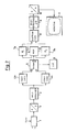
- (P1) and (P2) denote the optics of two projectors with which the light from two light sources (L1) and (L2) illuminated, arranged in the projectors, grids (G1) and (G2) the object to be measured (O) can be projected.
- the grids (G1) and (G2) have the same grating constant and lie in one plane at a distance (a) behind the projection centers of the optics (P1) and (P2).
- a stripe pattern with a sinusoidal intensity curve is applied to the grating.
- a video camera consisting of the camera optics (Bo) and the (K) designated camera sensor is arranged. This camera records the striped patterns of the two projectors (P1) and (P2) projected one after the other, deformed by the irregular object surface (O).
- the evaluation of the camera signals can best be described using the simplified block diagram in FIG. 2.
- the output of the CCD camera (1) is fed via an analog / digital converter (2) to an image memory (3) which temporarily stores the images of the stripe patterns projected one after the other.
- This image memory only serves as a buffer memory and is unnecessary if the subsequent electronics work fast enough.
- the digital video signal is then fed in parallel to two convolution modules (4a) and (4b), each of which calculates the sine (4a) and the cosine (4b) of the strip phase at these pixels from the vicinity of individual pixels.
- convolution modules (4a) and (4b) each of which calculates the sine (4a) and the cosine (4b) of the strip phase at these pixels from the vicinity of individual pixels.
- Corresponding algorithms are described, for example, in Optical Engineering, Vol. 23, No. 4 (July / August 1984) pages 391-395.
- the signals corresponding to the cosine and sine of the stripe phase are then fed to the inputs (A) and (B) of a module (5), which calculates the stripe phase ( ⁇ ) using a module (6) via the arctangent A / B in the phase values ( ⁇ ) in a look-up table are stored as a function of the arc tangent.
- the output of the component (5) is alternately connected to two image memories (7a) and (7b) connected in parallel via a multiplexer (12) synchronized with the camera (1).
- image memory In this image memory, the phase values ( ⁇ 1) for all the pixels of the stripe pattern (7a) projected via the projector (P1) and the phase values ( ⁇ 2) of the stripe pattern (7b) projected via the projector (P2) are separately read and buffered.
- Both image memories (7a) and (7b) are also connected to a subtraction stage (8).
- the difference ( ⁇ ) of the phases ( ⁇ 1) and ( ⁇ 2) of the two stripe patterns for the individual pixels is formed and fed to a further image memory (9).
- the stationary phase differences ( ⁇ ), which are a direct measure of the object distance z, are thus stored in this image memory (9).
- the buffer memory (9) is connected via a digital / analog converter (10) to the input of a monitor (11) on which the result is displayed.
- the points of the same phase difference result in contour lines whose shape describes the object surface.
- the image memory (9 ) the phase differences ( ⁇ ) are recorded from a large number of camera images taken in succession and averaged to improve the signal / noise ratio.
- the camera can be focused through in order to gradually focus on the entire object without the information about the object distance being distorted thereby.
- the two grids can be shifted together during the measurement process in order to optimally illuminate the object or additional, more precise ones based on the grid shift Apply phase measurement methods to the evaluation.
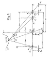
- a structure which consists essentially of three projectors with the projection optics (P1), (P2) and (P3) and three gratings (G1), (G2) and (G3), each with the same Grid period exists.
- the camera sensor is again designated (K) and is located with the observation lens (Bo) in front, as in the case already outlined in FIG. 1, between the projectors (P1) and (P2). While the projectors (P1) and (P2) are now inclined at a relatively large angle ( ⁇ 1) of approximately 30 ° to one another, the two projectors (P2) and (P3) arranged next to one another close a relatively small angle ( ⁇ 2) of, for example 0.5 ° on.
- This small, effective in the drawing plane angle ( ⁇ 2) can be realized in that the projector (P2) with the grating (G2) above the drawing plane and the projector (P3) with the grating (G3) is arranged below the drawing plane. Since a shift of the projectors and the grating parallel to the divisions of the grids has no influence on the evaluation of the images taken by the camera (K), the arrangement of the projection centers (Z 1), (Z 2) and (Z3) provided for simplification on a straight line.
- phase differences of the stripe pattern of the two projectors (P1) and (P2) and the phase differences of the two stripe patterns of the projectors (P2) and (P3) the successive surfaces of the same phase difference can be assigned different effective wavelengths ( ⁇ eff ) in the z direction.
- the effective wavelength ( ⁇ eff ) is determined by the grating constant of the grating (G1), (G2) and (G3) and the angle ( ⁇ 1) or ( ⁇ 2) between the projection axes of the respective projectors and depends on the grating constant of the grating (G1) to (G3) are the same, therefore only from the angles ( ⁇ 1) and ( ⁇ 2).
- the object coordinates (x), (y) and (z) can be calculated from the stripe patterns projected by the three projectors (P1), (P2) and (P3) for the individual points on the object surface.
- the projection centers (Z1), (Z2) and (Z3) of the projection lenses lie on a straight line extending in the x direction and the three grids (G1) to (G3) at an equal distance (a) behind these straight lines are arranged.
- the projection centers (Z1), (Z2) and (Z3) of the projection lenses lie on a straight line extending in the x direction and the three grids (G1) to (G3) at an equal distance (a) behind these straight lines are arranged.
- the grids are arranged on a common support (W) made of glass or a material with low thermal expansion coefficients, such as Zerodur, and can be used together in relation to the CCD camera (K) in the direction of the straight line (x) a spring rocker can be moved without play.
- the projectors (P1), (P2) and (P3) are arranged on a common carrier, not shown in Fig. 4, which consists of the same material as the carrier (W) of the grid. Adequate heat conduction between the two carriers ensures that the temperature difference between them is small. This reduces the influence of the ambient temperature on the measuring accuracy.
- the photosensitive surface of the camera ie the CCD sensor, is arranged at a distance (a K ) behind the observation objective (Bo).
- the geometry of the measuring device is essentially determined by the structure described.
- the center (x 0k ) of the observation lens (Bo) of the camera defines the origin of the coordinate system predetermined by the projectors (P1) to (P3).
- the formulas (11), (12) and (13) describe planes of constant phase difference (N i - ⁇ i ) between two projections, which are parallel to the x / y plane. They do not depend on the observation location (x k , y k ) on the camera. For the measurement, the integers (N1, N2, N3) and the fractions ( ⁇ 1, ⁇ 2, ⁇ 3) must be determined.
- Different effective wavelengths ( ⁇ eff ) of the phase differences can be assigned to the surfaces of the same phase difference, which are described by equations (11), (12) and (13).
- equations (11), (12) and (13) For the equation (11) obtained from a combination of the projectors (P1) and (P2) and the equation (12) obtained from a combination of the projectors (P1) and (P 3 ) there are relatively short effective wavelengths, while in the Equation (13) described case of the combination of the two projectors (P2) and (P3) a comparatively large wavelength ( ⁇ eff ) can be assigned. It is essential that the various effective wavelengths can be set in a highly stable manner between the projectors via the angles ( ⁇ 1), ( ⁇ 2).
- the projected stripe patterns of the three projectors (P1) to (P 3) are recorded in time-division multiplexing by the lens (Bo) of the camera (K) and read separately into different image memories.
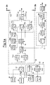
- the calculation of the object coordinates (x), (y) and (z) according to the formulas given then takes place as described below with reference to FIGS. 5a and 5b in a hardware-based image processing computer.
- This computer processes the image data in real time.
- it is constructed in the form of a pipeline structure with partially parallel data paths and is controlled by a host computer with a known von Neumann structure, that is to say, for example, a commercially available process computer.
- FIGS. 5a and 5b for a further description of the evaluation computer, reference is made to FIGS. 5a and 5b, in which it is shown in the block diagram.
- the functional module (A) represents the interface to the external sensors or parts of the device to be controlled. It contains an analog / digital converter (12) which digitizes the signal from the camera (K) in real-time video. The gain factor is controlled depending on the output signal of a photodiode (13), so that the video signal can be adapted to different brightness conditions or different energies of the light sources designed as flash lamps (L 1) to (L 3) (see FIGS. 3 and 4).
- To control the Flash lamps (L1) to (L3) contains the interface card (A) a trigger circuit (31) which is synchronized with the camera (K).
- the interface card (A) also contains the control electronics (32) for the motor, with which the lens (Bo) of the camera (K) can be focused on different object areas, as indicated in Fig. 4 by the arrow (Pf2).
- the sequence of the flashes and the adjustment of the lens is controlled in accordance with a defined measurement program of the conventional host computer, not shown in FIG. 5. This is symbolized by the two arrows "host”, which also appear elsewhere in the circuit according to FIGS. 5a and 5b.
- the digitized video signal which leaves the A / D converter (12), is fed to the inputs of two parallel convolution modules (14a) and (14b) in the function module (B). These two building blocks (14a) and (14b) carry out a folding operation in order to determine the sine or cosine of the strip phase at the individual object points, as has already been explained with reference to FIG. 2. Their outputs are fed to a circuit (15) in which the strip phase is calculated from the sine and the cosine. For this purpose, the function arctangent is stored in a table assigned to the circuit (15). At the same time, invalid measured values are masked on the basis of the phase values calculated in the circuit (15).
- Invalid measured values are those which were recorded with either too high or too low illumination intensity and whose level is therefore above or below a predetermined limit value.
- the mask which masks these image areas is generated in a circuit part denoted by (C) parallel to the measurement data stream, as will be described below.
- the output of the circuit (15) is three connected in parallel via a calculation stage (16) (arithmetic logic unit) Image memories (17a-c) supplied.
- the stripe phases ( ⁇ 1), ( ⁇ 2) and ( ⁇ 3) calculated by the three projectors (P1), (P2) and (P3) successively projected stripe patterns in time division multiplexing are temporarily stored in the circuit (15).
- Correction values are stored in three further image memories (18a), (18b) and (18c), which were obtained in a calibration process and which describe the distortions of the strip phase of the patterns projected by the three projectors, which result from the imperfection of the geometrical-optical structure of the device. These correction values are subtracted from the stripe phases ( ⁇ 1), ( ⁇ 2) and ( ⁇ 3) in the computing unit (16).
- the computing unit (19) is followed by a summation stage (S) (see FIG. 5b), which consists of a computing unit (20) and two RAM memories (21a) and (21b).
- S summation stage
- the phase differences ( ⁇ 1) and ( ⁇ 2) are accumulated for each pixel.
- This can e.g. in an integer arithmetic so that the 8 bit input values of the signals representing the phase differences ( ⁇ 1) and ( ⁇ 2) are summed up in a data area of 16 bits in the memories (22a) and (22b). In this way it is possible to average the phase differences obtained from 255 images by summation and thus to improve the accuracy of the phase measurement.
- the outputs of the image memories (21a) and (21b) are fed to two subsequent further computing units (22a) and (22b), in which further tables (look-up tables) the formulas for calculating the object distance according to equations (14) and (15) are available.
- These computing units (22a) and (22b) calculate two values for the object distance (z), which are averaged again in a subsequent computing stage (23).
- the coordinates (x) and (y) of the pixels according to equations (16) and (17) are determined from the measured values for (z) and the device constants (x k) supplied by the host computer ( y k) and (a k) calculated and fed to an output unit (25).
- the height information about the object to be measured is obtained absolutely and not only modulo 2 ⁇ of the strip phase.
- the evaluation method described above presupposes that the signals supplied by the camera (K) are generated in the linear region of the camera characteristic curve and that in particular there is no under- or over-control. Furthermore, it is necessary for the described method that within a recording series of the three stripe patterns projected by the projectors (P1), (P2) and (P3) a phase value is only processed if the phase values in all three images of the sequence for the particular one Pixels are valid. These arithmetic operations are carried out in the circuit part (C) of FIG. 5a. A bit in the look-up table LUT in the computing unit (15) queries whether a measured value is valid or invalid.
- the "and" link via the three video image sequences is generated in the computing stage (26) together with a recursively switched RAM module (27).
- the number of valid measured values at each pixel is calculated and stored in a subsequent RAM module (29).
- the number of measured values is to be understood here as the number of video images over which the phase differences in the summation module (S) of FIG. 5b are summed up. If you set a suitably chosen limit, the minimum number of describes valid measurements for each pixel, then all pixels are hidden in which the number of valid measurements is below this limit and all other pixels are included in the result calculation.
- the data mask described in this way, placed over the pixels is symbolized by the square (30) in FIG. 5a. It can be used to darken the video monitor (42) used for output at the corresponding pixels.
- the evaluation computer implemented in hardware and described with reference to FIGS. 5a and 5b represents a solution with which the signals of the camera can be processed in order to carry out the method according to the invention.
- This solution is tailored to the fact that the stripe patterns by the three projectors (P1), (P2) and (P3) are projected in time-division multiplex mode one after the other and the images are then taken and processed by the camera (K) one after the other.
- P1, P2) and (P3) are projected in time-division multiplex mode one after the other and the images are then taken and processed by the camera (K) one after the other.
- the stripe patterns for example in different colors, and record them simultaneously with three cameras separated by color dividers. Then, however, the input channel, i.e.
- the A / D converter (12), the convolution modules (14a) and (14b), the computing units (15) and (16), which operate in time-division multiplex operation, are executed in parallel in a corresponding number of three. Although this results in higher costs, it also offers a larger bandwidth in the processing frequency. Conversely, the arithmetic operations described can also be executed on a suitably programmed, suitably powerful, sequentially operating computer of conventional structure, but only there with considerably longer runtimes, so that real-time processing of the video signals cannot be achieved in this case.
- the z measurement is always the difference between two projections, for example the Stripe pattern of the projectors (P1) and (P2) or the projectors (P2) and (P3) is formed, the carrier (W) with the gratings (G1) to (G3) (see Fig. 4) in the direction of the arrow ( Pf1) are shifted without the z-values obtained in the signal evaluation being influenced.
- a separate light source (L1) to (L3) is provided for each projector.
Landscapes
- Physics & Mathematics (AREA)
- Engineering & Computer Science (AREA)
- Computer Vision & Pattern Recognition (AREA)
- General Physics & Mathematics (AREA)
- Optics & Photonics (AREA)
- Theoretical Computer Science (AREA)
- Length Measuring Devices By Optical Means (AREA)
- Measurement Of Optical Distance (AREA)
Applications Claiming Priority (2)
| Application Number | Priority Date | Filing Date | Title |
|---|---|---|---|
| DE4007502A DE4007502A1 (de) | 1990-03-09 | 1990-03-09 | Verfahren und vorrichtung zur beruehrungslosen vermessung von objektoberflaechen |
| DE4007502 | 1990-03-09 |
Publications (3)
| Publication Number | Publication Date |
|---|---|
| EP0451474A2 true EP0451474A2 (fr) | 1991-10-16 |
| EP0451474A3 EP0451474A3 (en) | 1992-03-25 |
| EP0451474B1 EP0451474B1 (fr) | 1994-07-27 |
Family
ID=6401803
Family Applications (1)
| Application Number | Title | Priority Date | Filing Date |
|---|---|---|---|
| EP91102737A Expired - Lifetime EP0451474B1 (fr) | 1990-03-09 | 1991-02-25 | Procédé et dispositif pour mesurer sans contact le contour superficiel d'un objet |
Country Status (4)
| Country | Link |
|---|---|
| US (1) | US5135308A (fr) |
| EP (1) | EP0451474B1 (fr) |
| JP (1) | JPH04220510A (fr) |
| DE (2) | DE4007502A1 (fr) |
Cited By (2)
| Publication number | Priority date | Publication date | Assignee | Title |
|---|---|---|---|---|
| EP0563829A3 (en) * | 1992-03-30 | 1994-08-24 | Sharp Kk | Device for inspecting printed cream solder |
| DE4416108A1 (de) * | 1994-05-06 | 1995-11-09 | Fraunhofer Ges Forschung | Vorrichtung zum berührungsfreien Vermessen einer Objektoberfläche |
Families Citing this family (66)
| Publication number | Priority date | Publication date | Assignee | Title |
|---|---|---|---|---|
| US5343294A (en) * | 1990-03-09 | 1994-08-30 | Carl-Zeiss-Stiftung | Method for analyzing periodic brightness patterns |
| DE4027328B4 (de) * | 1990-08-29 | 2004-07-22 | Sirona Dental Systems Gmbh | 3D-Kamera zur Erfassung von Oberflächenstrukturen, insbesondere für zahnmedizinische Zwecke |
| DE4134546A1 (de) * | 1991-09-26 | 1993-04-08 | Steinbichler Hans | Verfahren und vorrichtung zur bestimmung der absolut-koordinaten eines objektes |
| NL9200071A (nl) * | 1992-01-15 | 1993-08-02 | Stichting Science Park Maastri | Inrichting voor het bepalen van de topografie van een gekromd oppervlak. |
| US5636025A (en) * | 1992-04-23 | 1997-06-03 | Medar, Inc. | System for optically measuring the surface contour of a part using more fringe techniques |
| DE4217768A1 (de) * | 1992-05-29 | 1993-12-02 | Zeiss Carl Fa | Verfahren und Vorrichtung zur Vermessung von Objekttopographien mittels projizierter Streifenmuster |
| US6252242B1 (en) * | 1992-12-03 | 2001-06-26 | Brown & Sharpe Surface Inspection Systems, Inc. | High speed optical inspection apparatus using Gaussian distribution analysis and method therefore |
| DE4308082A1 (de) * | 1993-03-13 | 1994-09-15 | Gerhard Dr Kleemann | Verfahren und Einrichtung zur optischen Messung von Objekten in einer Ebene |
| DE19536297C2 (de) * | 1995-09-29 | 2003-10-02 | Daimler Chrysler Ag | Verfahren zur geometrischen Kalibrierung von optischen 3D-Sensoren zur dreidimensionalen Vermessung von Objekten und Vorrichtung hierzu |
| DE19545367C2 (de) * | 1995-12-05 | 2001-07-12 | Fraunhofer Ges Forschung | Vorrichtung und Verfahren zur optischen Profilmessung, insbesondere an gekrümmten Objektoberflächen |
| US5646733A (en) * | 1996-01-29 | 1997-07-08 | Medar, Inc. | Scanning phase measuring method and system for an object at a vision station |
| US6690474B1 (en) * | 1996-02-12 | 2004-02-10 | Massachusetts Institute Of Technology | Apparatus and methods for surface contour measurement |
| US5838428A (en) * | 1997-02-28 | 1998-11-17 | United States Of America As Represented By The Secretary Of The Navy | System and method for high resolution range imaging with split light source and pattern mask |
| US6873340B2 (en) | 1997-05-15 | 2005-03-29 | Visimatix, Inc. | Method and apparatus for an automated reference indicator system for photographic and video images |
| DE19749435B4 (de) * | 1997-11-09 | 2005-06-02 | Mähner, Bernward | Verfahren und Vorrichtung zur dreidimensionalen, flächenhaften, optischen Vermessung von Objekten |
| USD427243S (en) * | 1997-12-15 | 2000-06-27 | Visimatix, Inc. | Reference indicator patch for use in an automated reference indicator system for photographic and video images |
| JP3417377B2 (ja) * | 1999-04-30 | 2003-06-16 | 日本電気株式会社 | 三次元形状計測方法及び装置並びに記録媒体 |
| US6261693B1 (en) * | 1999-05-03 | 2001-07-17 | Guardian Industries Corporation | Highly tetrahedral amorphous carbon coating on glass |
| US6763133B1 (en) * | 1999-05-29 | 2004-07-13 | Sun Moon University | Moire image capturing apparatus and method therefor |
| US6208412B1 (en) | 1999-06-14 | 2001-03-27 | Visteon Global Technologies, Inc. | Method and apparatus for determining optical quality |
| US6100990A (en) * | 1999-06-14 | 2000-08-08 | Ford Motor Company | Method and apparatus for determining reflective optical quality using gray-scale patterns |
| GB2375392B (en) | 2000-01-07 | 2004-12-15 | Cyberoptics Corp | Phase profilometry system with telecentric projector |
| US6593705B1 (en) | 2000-01-07 | 2003-07-15 | Cyberoptics Corporation | Rapid-firing flashlamp discharge circuit |
| US6750899B1 (en) | 2000-01-07 | 2004-06-15 | Cyberoptics Corporation | Solder paste inspection system |
| US6549647B1 (en) | 2000-01-07 | 2003-04-15 | Cyberoptics Corporation | Inspection system with vibration resistant video capture |
| DE10025741C2 (de) * | 2000-05-19 | 2002-06-13 | Fraunhofer Ges Forschung | Verfahren zur Bestimmung der räumlichen Koordinaten von Gegenständen und/oder deren zeitlicher Änderung |
| US20020053647A1 (en) * | 2000-11-06 | 2002-05-09 | Masataka Shiratsuchi | Pattern detection, processing and testing apparatus |
| GB2372656A (en) * | 2001-02-23 | 2002-08-28 | Ind Control Systems Ltd | Optical position determination |
| DE10130902A1 (de) * | 2001-06-27 | 2003-01-16 | Zeiss Carl | Interferometersystem, Verfahren zum Aufnehmen eines Interferogramms und Verfahren zum Bereitstellen und Herstellen eines Objekts mit einer Soll-Oberfläche |
| US6634552B2 (en) * | 2001-09-26 | 2003-10-21 | Nec Laboratories America, Inc. | Three dimensional vision device and method, and structured light bar-code patterns for use in the same |
| US7525669B1 (en) * | 2004-07-09 | 2009-04-28 | Mohsen Abdollahi | High-speed, scanning phase-shifting profilometry using 2D CMOS sensor |
| DE102005018656B4 (de) | 2005-04-21 | 2007-04-12 | GOM - Gesellschaft für Optische Meßtechnik mbH | Projektor für eine Anordnung zum dreidimensionalen optischen Vermessen von Objekten |
| JP4701948B2 (ja) | 2005-09-21 | 2011-06-15 | オムロン株式会社 | パタン光照射装置、3次元形状計測装置、及びパタン光照射方法 |
| DE102005058873A1 (de) * | 2005-12-09 | 2007-06-14 | Fraunhofer-Gesellschaft zur Förderung der angewandten Forschung e.V. | Vorrichtung und Verfahren zur Vermessung der Oberfläche eines Körpers |
| US7830528B2 (en) | 2005-12-14 | 2010-11-09 | Koh Young Technology, Inc. | 3D image measuring apparatus and method thereof |
| US7545512B2 (en) | 2006-01-26 | 2009-06-09 | Koh Young Technology Inc. | Method for automated measurement of three-dimensional shape of circuit boards |
| US8054471B2 (en) * | 2006-09-15 | 2011-11-08 | Sciammarella Cesar A | System and method for analyzing displacements and contouring of surfaces |
| WO2008086016A1 (fr) * | 2007-01-10 | 2008-07-17 | Cyberoptics Corporation | Système d'inspection |
| DE102007054906B4 (de) * | 2007-11-15 | 2011-07-28 | Sirona Dental Systems GmbH, 64625 | Verfahren zur optischen Vermessung der dreidimensionalen Geometrie von Objekten |
| DE102007054907A1 (de) * | 2007-11-15 | 2009-05-28 | Sirona Dental Systems Gmbh | Verfahren zur optischen Vermessung von Objekten unter Verwendung eines Triangulationsverfahrens |
| US8059280B2 (en) | 2008-01-31 | 2011-11-15 | Cyberoptics Corporation | Method for three-dimensional imaging using multi-phase structured light |
| US7969583B2 (en) * | 2008-03-05 | 2011-06-28 | General Electric Company | System and method to determine an object distance from a reference point to a point on the object surface |
| US8107083B2 (en) | 2008-03-05 | 2012-01-31 | General Electric Company | System aspects for a probe system that utilizes structured-light |
| US7821649B2 (en) * | 2008-03-05 | 2010-10-26 | Ge Inspection Technologies, Lp | Fringe projection system and method for a probe suitable for phase-shift analysis |
| US8422030B2 (en) | 2008-03-05 | 2013-04-16 | General Electric Company | Fringe projection system with intensity modulating by columns of a plurality of grating elements |
| DE102010064593A1 (de) * | 2009-05-21 | 2015-07-30 | Koh Young Technology Inc. | Formmessgerät und -verfahren |
| EP2272417B1 (fr) * | 2009-07-10 | 2016-11-09 | GE Inspection Technologies, LP | Système de projection de frange pour sonde adapté à une analyse de commutation de phase |
| CN101957496B (zh) * | 2009-07-17 | 2014-12-17 | 通用电气检查技术有限合伙人公司 | 适于相移分析的探头的条纹投射系统和方法 |
| DE102009040991B4 (de) | 2009-09-10 | 2012-11-08 | Carl Zeiss Ag | Messanordnung und Verfahren zum Vermessen einer Oberfläche |
| US8414124B2 (en) | 2009-10-21 | 2013-04-09 | Sis Ag, Surgical Instrument Systems | Device and method for measuring a cornea |
| EP2314200B1 (fr) * | 2009-10-21 | 2016-01-13 | SIS AG, Surgical Instrument Systems | Dispositif et procédé destinés à la mesure d'une cornée |
| TW201120405A (en) * | 2009-12-11 | 2011-06-16 | Jeteazy System Co Ltd | Height measurement device having probe and method for using the device to measure height. |
| US8134719B2 (en) * | 2010-03-19 | 2012-03-13 | Carestream Health, Inc. | 3-D imaging using telecentric defocus |
| JP5995484B2 (ja) * | 2012-03-30 | 2016-09-21 | キヤノン株式会社 | 三次元形状測定装置、三次元形状測定方法、及びプログラム |
| DE102012112321B4 (de) * | 2012-12-14 | 2015-03-05 | Faro Technologies, Inc. | Vorrichtung zum optischen Abtasten und Vermessen einer Umgebung |
| US20140293011A1 (en) * | 2013-03-28 | 2014-10-02 | Phasica, LLC | Scanner System for Determining the Three Dimensional Shape of an Object and Method for Using |
| US10126252B2 (en) | 2013-04-29 | 2018-11-13 | Cyberoptics Corporation | Enhanced illumination control for three-dimensional imaging |
| EP2799810A1 (fr) * | 2013-04-30 | 2014-11-05 | Aimess Services GmbH | Dispositif et procédé de mesure tridimensionnelle simultanée de surfaces avec plusieurs longueurs d'onde |
| JP6434788B2 (ja) * | 2014-03-06 | 2018-12-05 | パナソニック インテレクチュアル プロパティ コーポレーション オブ アメリカPanasonic Intellectual Property Corporation of America | 計測システム、計測方法およびビジョンチップ |
| US9964402B2 (en) | 2015-04-24 | 2018-05-08 | Faro Technologies, Inc. | Two-camera triangulation scanner with detachable coupling mechanism |
| US10554956B2 (en) | 2015-10-29 | 2020-02-04 | Dell Products, Lp | Depth masks for image segmentation for depth-based computational photography |
| US10021371B2 (en) | 2015-11-24 | 2018-07-10 | Dell Products, Lp | Method and apparatus for gross-level user and input detection using similar or dissimilar camera pair |
| EP3543522A1 (fr) * | 2018-03-22 | 2019-09-25 | Siemens Gamesa Renewable Energy A/S | Système de surveillance de pale de rotor |
| DE102020109945A1 (de) * | 2020-04-09 | 2021-10-14 | Isra Vision Ag | Verfahren und Inspektionseinrichtung zur optischen Inspektion einer Oberfläche |
| CN112697258A (zh) * | 2020-12-17 | 2021-04-23 | 天津大学 | 一种基于单帧编码照明的视觉振动测量方法 |
| WO2022178678A1 (fr) * | 2021-02-23 | 2022-09-01 | 华为技术有限公司 | Système optique, appareil et terminal |
Family Cites Families (9)
| Publication number | Priority date | Publication date | Assignee | Title |
|---|---|---|---|---|
| US3894802A (en) * | 1973-04-16 | 1975-07-15 | Bendix Corp | Stereoscopic gage and gaging system |
| US4316670A (en) * | 1979-05-29 | 1982-02-23 | Beta Industries, Inc. | Apparatus and method for determining the configuration of a reflective surface |
| US4488172A (en) * | 1982-08-18 | 1984-12-11 | Novon, Inc. | Method and apparatus for range imaging |
| US4499492A (en) * | 1982-08-18 | 1985-02-12 | Novon, Inc. | Method and apparatus for three frame range imaging |
| US4564295A (en) * | 1983-03-07 | 1986-01-14 | New York Institute Of Technology | Apparatus and method for projection moire topography |
| US4641972A (en) * | 1984-09-14 | 1987-02-10 | New York Institute Of Technology | Method and apparatus for surface profilometry |
| JPH061164B2 (ja) * | 1985-01-31 | 1994-01-05 | 伍良 松本 | 立体形状測定装置 |
| EP0262089A3 (fr) * | 1986-09-23 | 1989-08-09 | KERN & CO. AG Werke für Präzisionsmechanik Optik und Elektronik | Dispositif pour mesurer la surface d'un objet |
| US5085502A (en) * | 1987-04-30 | 1992-02-04 | Eastman Kodak Company | Method and apparatus for digital morie profilometry calibrated for accurate conversion of phase information into distance measurements in a plurality of directions |
-
1990
- 1990-03-09 DE DE4007502A patent/DE4007502A1/de not_active Withdrawn
-
1991
- 1991-02-25 DE DE59102307T patent/DE59102307D1/de not_active Expired - Fee Related
- 1991-02-25 EP EP91102737A patent/EP0451474B1/fr not_active Expired - Lifetime
- 1991-03-08 JP JP3043366A patent/JPH04220510A/ja active Pending
- 1991-03-08 US US07/666,363 patent/US5135308A/en not_active Expired - Lifetime
Cited By (3)
| Publication number | Priority date | Publication date | Assignee | Title |
|---|---|---|---|---|
| EP0563829A3 (en) * | 1992-03-30 | 1994-08-24 | Sharp Kk | Device for inspecting printed cream solder |
| DE4416108A1 (de) * | 1994-05-06 | 1995-11-09 | Fraunhofer Ges Forschung | Vorrichtung zum berührungsfreien Vermessen einer Objektoberfläche |
| DE4416108C2 (de) * | 1994-05-06 | 2000-05-11 | Fraunhofer Ges Forschung | Vorrichtung zum berührungsfreien Vermessen einer Objektoberfläche |
Also Published As
| Publication number | Publication date |
|---|---|
| JPH04220510A (ja) | 1992-08-11 |
| DE59102307D1 (de) | 1994-09-01 |
| EP0451474A3 (en) | 1992-03-25 |
| EP0451474B1 (fr) | 1994-07-27 |
| US5135308A (en) | 1992-08-04 |
| DE4007502A1 (de) | 1991-09-12 |
Similar Documents
| Publication | Publication Date | Title |
|---|---|---|
| EP0451474B1 (fr) | Procédé et dispositif pour mesurer sans contact le contour superficiel d'un objet | |
| EP0445618B1 (fr) | Dispositif et procédé pour mesurer sans contact la superficie d'objets | |
| EP0076866B1 (fr) | Procédé interpolant de la coupe optique | |
| DE69207176T2 (de) | Optischer Sensor | |
| DE4204857C2 (de) | Verfahren zur Untersuchung einer Oberflächenform mit einem Interferometer | |
| DE3907430C1 (fr) | ||
| DE9017720U1 (de) | Vorrichtung zur direkten Phasenmessung von Strahlung, insbesondere Lichtstrahlung | |
| CH692873A5 (de) | Vorrichtung und Verfahren zur geometrischen Kalibrierung von CCD-Kameras. | |
| DE102018114860A1 (de) | Vorrichtung und Verfahren zur optischen Vermessung eines Messobjekts | |
| CH626169A5 (fr) | ||
| DE2354141C2 (de) | Optisches Meßverfahren zum Untersuchen von Oberflächen und Einrichtung zur Durchführung des Verfahrens | |
| EP2799810A1 (fr) | Dispositif et procédé de mesure tridimensionnelle simultanée de surfaces avec plusieurs longueurs d'onde | |
| DE4436500A1 (de) | Optisches Projektionsgitter | |
| DE2653545B1 (de) | Fotoelektrische Auflicht-Wegmesseinrichtung | |
| DE4036120A1 (de) | Verfahren und vorrichtung zur bestimmung der wegaenderung von strahlen, vorzugsweise lichtstrahlen | |
| DE2620330A1 (de) | Verfahren und vorrichtung zur bestimmung einer oberflaechengestalt | |
| DE3413605C2 (fr) | ||
| DE102023205077B4 (de) | Verfahren und Vorrichtung zur Bestimmung einer objektabhängigen Fokusablage, Verfahren zur Vermessung eines Objekts und Koordinatenmessgerät | |
| DE19513233C2 (de) | Verfahren und Vorrichtung zur Bestimmung von Phasen und Phasendifferenzen | |
| DE4119744B4 (de) | Verfahren zur Auswertung periodischer Helligkeitsmuster | |
| DE4129796A1 (de) | Verfahren und vorrichtung zur beruehrungslosen vermessung von objektoberflaechen | |
| DE3934423C1 (en) | Camera photographing topography of test piece surface - produces Moire image using CCD sensors recording phase shift between object grating and camera reference grating | |
| EP1273878B1 (fr) | Procédé pour détecter un objet en utilisant de résolutions différentes | |
| DE102020110298A1 (de) | Vorrichtung und Verfahren zur optischen Messung einer Oberflächentopographie | |
| DE102023120240B4 (de) | Aufnahmevorrichtung zum Erzeugen einer 3D-Aufnahme eines dreidimensionalen Objekts und Verfahren |
Legal Events
| Date | Code | Title | Description |
|---|---|---|---|
| PUAI | Public reference made under article 153(3) epc to a published international application that has entered the european phase |
Free format text: ORIGINAL CODE: 0009012 |
|
| AK | Designated contracting states |
Kind code of ref document: A2 Designated state(s): CH DE FR GB IT LI |
|
| PUAL | Search report despatched |
Free format text: ORIGINAL CODE: 0009013 |
|
| AK | Designated contracting states |
Kind code of ref document: A3 Designated state(s): CH DE FR GB IT LI |
|
| 17P | Request for examination filed |
Effective date: 19920910 |
|
| 17Q | First examination report despatched |
Effective date: 19931014 |
|
| ITF | It: translation for a ep patent filed | ||
| GRAA | (expected) grant |
Free format text: ORIGINAL CODE: 0009210 |
|
| AK | Designated contracting states |
Kind code of ref document: B1 Designated state(s): CH DE FR GB IT LI |
|
| REF | Corresponds to: |
Ref document number: 59102307 Country of ref document: DE Date of ref document: 19940901 |
|
| GBT | Gb: translation of ep patent filed (gb section 77(6)(a)/1977) |
Effective date: 19941024 |
|
| ET | Fr: translation filed | ||
| PLBE | No opposition filed within time limit |
Free format text: ORIGINAL CODE: 0009261 |
|
| STAA | Information on the status of an ep patent application or granted ep patent |
Free format text: STATUS: NO OPPOSITION FILED WITHIN TIME LIMIT |
|
| 26N | No opposition filed | ||
| REG | Reference to a national code |
Ref country code: GB Ref legal event code: IF02 |
|
| PGFP | Annual fee paid to national office [announced via postgrant information from national office to epo] |
Ref country code: DE Payment date: 20090219 Year of fee payment: 19 |
|
| PGFP | Annual fee paid to national office [announced via postgrant information from national office to epo] |
Ref country code: CH Payment date: 20090217 Year of fee payment: 19 Ref country code: GB Payment date: 20090219 Year of fee payment: 19 |
|
| PGFP | Annual fee paid to national office [announced via postgrant information from national office to epo] |
Ref country code: IT Payment date: 20090221 Year of fee payment: 19 |
|
| PGFP | Annual fee paid to national office [announced via postgrant information from national office to epo] |
Ref country code: FR Payment date: 20090213 Year of fee payment: 19 |
|
| REG | Reference to a national code |
Ref country code: CH Ref legal event code: PL |
|
| GBPC | Gb: european patent ceased through non-payment of renewal fee |
Effective date: 20100225 |
|
| PG25 | Lapsed in a contracting state [announced via postgrant information from national office to epo] |
Ref country code: CH Free format text: LAPSE BECAUSE OF NON-PAYMENT OF DUE FEES Effective date: 20100228 Ref country code: LI Free format text: LAPSE BECAUSE OF NON-PAYMENT OF DUE FEES Effective date: 20100228 |
|
| REG | Reference to a national code |
Ref country code: FR Ref legal event code: ST Effective date: 20101029 |
|
| PG25 | Lapsed in a contracting state [announced via postgrant information from national office to epo] |
Ref country code: FR Free format text: LAPSE BECAUSE OF NON-PAYMENT OF DUE FEES Effective date: 20100301 |
|
| PG25 | Lapsed in a contracting state [announced via postgrant information from national office to epo] |
Ref country code: DE Free format text: LAPSE BECAUSE OF NON-PAYMENT OF DUE FEES Effective date: 20100901 |
|
| PG25 | Lapsed in a contracting state [announced via postgrant information from national office to epo] |
Ref country code: GB Free format text: LAPSE BECAUSE OF NON-PAYMENT OF DUE FEES Effective date: 20100225 Ref country code: IT Free format text: LAPSE BECAUSE OF NON-PAYMENT OF DUE FEES Effective date: 20100225 |