EP0451493A1 - Guide d'ondes diélectrique - Google Patents
Guide d'ondes diélectrique Download PDFInfo
- Publication number
- EP0451493A1 EP0451493A1 EP91103155A EP91103155A EP0451493A1 EP 0451493 A1 EP0451493 A1 EP 0451493A1 EP 91103155 A EP91103155 A EP 91103155A EP 91103155 A EP91103155 A EP 91103155A EP 0451493 A1 EP0451493 A1 EP 0451493A1
- Authority
- EP
- European Patent Office
- Prior art keywords
- dielectric
- conductor
- webs
- dielectric waveguide
- curvature
- Prior art date
- Legal status (The legal status is an assumption and is not a legal conclusion. Google has not performed a legal analysis and makes no representation as to the accuracy of the status listed.)
- Ceased
Links
- 239000004020 conductor Substances 0.000 claims abstract description 18
- 238000009826 distribution Methods 0.000 description 8
- 238000013016 damping Methods 0.000 description 3
- 229920000642 polymer Polymers 0.000 description 3
- 238000005452 bending Methods 0.000 description 2
- 239000004698 Polyethylene Substances 0.000 description 1
- 230000001419 dependent effect Effects 0.000 description 1
- 238000004519 manufacturing process Methods 0.000 description 1
- 230000003287 optical effect Effects 0.000 description 1
- -1 polyethylene Polymers 0.000 description 1
- 229920000573 polyethylene Polymers 0.000 description 1
- 239000000843 powder Substances 0.000 description 1
- 230000005855 radiation Effects 0.000 description 1
- 239000007787 solid Substances 0.000 description 1
Images
Classifications
-
- H—ELECTRICITY
- H01—ELECTRIC ELEMENTS
- H01P—WAVEGUIDES; RESONATORS, LINES, OR OTHER DEVICES OF THE WAVEGUIDE TYPE
- H01P1/00—Auxiliary devices
- H01P1/02—Bends; Corners; Twists
-
- G—PHYSICS
- G02—OPTICS
- G02B—OPTICAL ELEMENTS, SYSTEMS OR APPARATUS
- G02B6/00—Light guides; Structural details of arrangements comprising light guides and other optical elements, e.g. couplings
- G02B6/02—Optical fibres with cladding with or without a coating
-
- H—ELECTRICITY
- H01—ELECTRIC ELEMENTS
- H01P—WAVEGUIDES; RESONATORS, LINES, OR OTHER DEVICES OF THE WAVEGUIDE TYPE
- H01P3/00—Waveguides; Transmission lines of the waveguide type
- H01P3/16—Dielectric waveguides, i.e. without a longitudinal conductor
Definitions
- dielectric waveguides are used as an alternative to the metallic waveguides because they have a comparatively low attenuation.
- a rod-shaped dielectric waveguide consisting of a low-loss dielectric and surrounded by air is known, for example, from Int. J. Electronics, 1975, Vol. 39, No. 3, pages 275 - 287.
- a rod made of a solid dielectric can only be bent with a large radius relative to the rod diameter because of its great bending stiffness. Proposals are known from the literature on how to make dielectric waveguides more flexible. In IEEE Transactions on Microwave Theory and Technics, Vol. 36, No.
- pages 882-890 describes a dielectric line consisting of a polymer tube, which is filled with a powder made of a dielectric of high dielectric constant. From the microwave magazine, Vol. 14, No. 7, 1988, pages 656-658 shows a flexible dielectric line, the core of which consists of a dense microporous polymer and is surrounded by a jacket of a less dense microporous polymer. All these known lines may only be laid with a relatively large radius of curvature, so that excessive power losses due to radiation do not occur in the area of curvature.
- the curvature damping disappears if the following optimal distribution of the dielectric constant is realized in the curved region of the dielectric waveguide:
- R is the radius of curvature
- r the distance of the point of incidence from the axis of curvature
- ⁇ g (x, y) the transverse distribution of the dielectric constant in the straight dielectric line.
- a surface waveguide which consists of a metallic conductor coated with a dielectric.
- the dielectric layer of this surface waveguide also known as a Harms-Goubau line, is applied to the metallic conductor in the form of webs. This is shaped into webs Dielectric layer ensures good flexibility of the surface waveguide even with a large layer thickness and even when using a very brittle dielectric with a low loss angle.
- the invention is based on the object of specifying a flexible dielectric waveguide which has the lowest possible curvature damping.
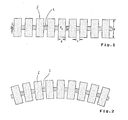
- the dielectric waveguide shown in Figures 1 and 2 consists of a thin, for. B. rod-shaped, central flexible conductor L, on which a plurality of mutually spaced dielectric disks S is lined up.
- the central conductor L consists of a dielectric with the dielectric constant ⁇ 2.
- the dielectric disks S have a dielectric constant ⁇ 1, which is either the same or different from the dielectric constant ⁇ 2 of the central dielectric conductor L.
- the central conductor L can be rod-shaped with a round or polygonal cross section. However, it can also be designed as a planar line (strip line, island line, inverted strip line, etc.).
- the width of the individual dielectric slices S is to be dimensioned such that they are small compared to the wavelength of the wave guided by the conductor (for example, HE 11). Then the dielectric waveguide behaves like a longitudinally homogeneous dielectric line with constant cross-sectional dimensions.
- the transverse distribution of the dielectric constant is symmetrical with respect to the line axis. If the line is now curved (cf. FIG. 2), the distances between the dielectric disks S on the inside of the arc decrease and increase on the outside of the arc. This increases the effective local dielectric constant - that is the dielectric constant averaged over a period - on the inside of the sheet, while it is reduced on the outside of the sheet. The shear of the distribution of the dielectric constant becomes stronger the more the dielectric waveguide is bent. In this way, a distribution of the dielectric constant that is adapted to each curvature is achieved, which is very close to the optimal shape according to the equation specified at the beginning.
- the dielectric disks S have a constant thickness.
- the thickness of the dielectric slices S can change depending on the distance from the longitudinal axis of the line. It can thus be achieved that the dielectric constant of the equivalent, longitudinally homogeneous, straight waveguide is also dependent on the distance from its line axis. In this way, any radial distributions of the dielectric constants of the dielectric waveguide can be realized. It is to be expected that, after the submillimeter wavelength range has been developed, dielectric waveguides with special distributions of the dielectric constants will also become important.
- the central conductor L is rod-shaped with a round cross-section and the dielectric disks S which are placed concentrically thereon are circular.
- the preceding description relates to waveguides for the microwave range.
- the invention can also be applied to waveguides which are designed for the optical wavelength range.
Landscapes
- Physics & Mathematics (AREA)
- General Physics & Mathematics (AREA)
- Optics & Photonics (AREA)
- Waveguide Aerials (AREA)
Applications Claiming Priority (2)
| Application Number | Priority Date | Filing Date | Title |
|---|---|---|---|
| DE19904011829 DE4011829A1 (de) | 1990-04-12 | 1990-04-12 | Dielektrischer wellenleiter |
| DE4011829 | 1990-04-12 |
Publications (1)
| Publication Number | Publication Date |
|---|---|
| EP0451493A1 true EP0451493A1 (fr) | 1991-10-16 |
Family
ID=6404269
Family Applications (1)
| Application Number | Title | Priority Date | Filing Date |
|---|---|---|---|
| EP91103155A Ceased EP0451493A1 (fr) | 1990-04-12 | 1991-03-02 | Guide d'ondes diélectrique |
Country Status (2)
| Country | Link |
|---|---|
| EP (1) | EP0451493A1 (fr) |
| DE (1) | DE4011829A1 (fr) |
Cited By (1)
| Publication number | Priority date | Publication date | Assignee | Title |
|---|---|---|---|---|
| EP3760984A1 (fr) * | 2019-07-03 | 2021-01-06 | Rosemount Tank Radar AB | Sonde de ligne de transmission |
Citations (5)
| Publication number | Priority date | Publication date | Assignee | Title |
|---|---|---|---|---|
| FR1099862A (fr) * | 1953-05-04 | 1955-09-12 | Siemens Ag | Disposition avec des guides d'ondes en matière diélectrique |
| FR1195952A (fr) * | 1957-05-17 | 1959-11-20 | Ici Ltd | Guides d'ondes tubulaires |
| GB835976A (en) * | 1957-02-08 | 1960-06-01 | Lignes Telegraph Telephon | Improvements in or relating to surface wave transmission lines |
| FR1372610A (fr) * | 1963-08-06 | 1964-09-18 | Ligne de transmission avec diélectrique | |
| USH584H (en) * | 1986-12-18 | 1989-02-07 | The United States Of America As Represented By The Secretary Of The Army | Dielectric omni-directional antennas |
Family Cites Families (2)
| Publication number | Priority date | Publication date | Assignee | Title |
|---|---|---|---|---|
| DE899685C (de) * | 1950-11-18 | 1953-12-14 | Lorenz C Ag | Wellenleiter fuer elektromagnetische Oberflaechenwellen |
| DE3214471A1 (de) * | 1982-04-20 | 1983-10-27 | Philips Kommunikations Industrie AG, 8500 Nürnberg | Gekruemmte dielektrische leitung mit kleinem kruemmungsradius |
-
1990
- 1990-04-12 DE DE19904011829 patent/DE4011829A1/de not_active Ceased
-
1991
- 1991-03-02 EP EP91103155A patent/EP0451493A1/fr not_active Ceased
Patent Citations (5)
| Publication number | Priority date | Publication date | Assignee | Title |
|---|---|---|---|---|
| FR1099862A (fr) * | 1953-05-04 | 1955-09-12 | Siemens Ag | Disposition avec des guides d'ondes en matière diélectrique |
| GB835976A (en) * | 1957-02-08 | 1960-06-01 | Lignes Telegraph Telephon | Improvements in or relating to surface wave transmission lines |
| FR1195952A (fr) * | 1957-05-17 | 1959-11-20 | Ici Ltd | Guides d'ondes tubulaires |
| FR1372610A (fr) * | 1963-08-06 | 1964-09-18 | Ligne de transmission avec diélectrique | |
| USH584H (en) * | 1986-12-18 | 1989-02-07 | The United States Of America As Represented By The Secretary Of The Army | Dielectric omni-directional antennas |
Non-Patent Citations (3)
| Title |
|---|
| JOURNAL OF APPLIED PHYSICS, vol. 57, no. 3, Februar 1985, NEW YORK, US; Seiten 943 - 955; M.T.WLODARCZYK ET AL.: "Excitation and scattering of guided modes on a dielectric cylinder with a periodically varying radius" * |
| PATENT ABSTRACTS OF JAPAN, vol. 1, no. 103 (E-77)[3274] 13 September 1977; & JP-A-52 035 890 (NIPPON DESHIN DENWA KOSHA) 18 März 1977, * |
| SOVIET INVENTIONS ILLUSTRATED, Week E21, 07-07-1982, Section W; & SU-A-853721 (BEZBORODOV), 17-08-1981 * |
Cited By (2)
| Publication number | Priority date | Publication date | Assignee | Title |
|---|---|---|---|---|
| EP3760984A1 (fr) * | 2019-07-03 | 2021-01-06 | Rosemount Tank Radar AB | Sonde de ligne de transmission |
| US11435214B2 (en) | 2019-07-03 | 2022-09-06 | Rosemount Tank Radar Ab | Transmission line probe |
Also Published As
| Publication number | Publication date |
|---|---|
| DE4011829A1 (de) | 1991-10-17 |
Similar Documents
| Publication | Publication Date | Title |
|---|---|---|
| DE112008001139B4 (de) | Gradienten-Index-Linse für Mikrowellenstrahlung | |
| DE3586134T2 (de) | Roentgenaufnahmegeraet mit schlitzblende, enthaltend einzeln steuerbare absorptionselemente zusammenwirkend mit der schlitzblende. | |
| DE2718785A1 (de) | Optische fasern mit brechungsindexgradienten | |
| DE6945245U (de) | Elektrisches fernmeldekabel | |
| DE1004248B (de) | Resonanzabsorber zur Schluckung elektromagnetischer Zentimeterwellen | |
| DE1690288B2 (de) | Trommelbarer Hohlleiter | |
| DE2161904A1 (de) | Koaxialkabel mit flachem Profil | |
| DE102016122511A1 (de) | Dielektrische Wellenleiterbahnvorrichtung | |
| DE2525495C2 (de) | Flexibler schraubenlinienförmig gewellter, längsnahtgeschweißter Rechteckhohlleiter | |
| DE1640696A1 (de) | Koaxiales Hochfrequenzkabel mit Hohlraumisolierung | |
| DE2011554A1 (de) | Wendelhohlleiter | |
| DE4011829A1 (de) | Dielektrischer wellenleiter | |
| DE2235346A1 (de) | Hohlleiter-wellentyp-filter mit kreisquerschnitt | |
| EP2553757B1 (fr) | Structure de conducteurs coaxiaux | |
| DE1765940A1 (de) | Hohlleiter mit Wendelstruktur und Verfahren zu dessen Herstellung | |
| DE899685C (de) | Wellenleiter fuer elektromagnetische Oberflaechenwellen | |
| EP1011178A1 (fr) | Amplificateur laser de puissance, procédé de production et son utilisation | |
| DE1616252B2 (de) | Breitband-Rundstrahlantenne für Mikrowellen, bestehend aus einem vertikalen Rundhohlleiter und wenigstens einem Kegelreflektor | |
| DE2836869C2 (de) | Rillenhornstrahler | |
| DE2051851A1 (de) | Verfahren zur Erzeugung von Subwellen | |
| DE3116964C2 (de) | Kabel | |
| DE1076761B (de) | Gekruemmter Hohlleiterabschnitt oder Kruemmer | |
| DE821053C (de) | UEbertragungselement zur UEbertragung hochfrequenter, elektromagnetischer Wellen | |
| DE3032644C2 (de) | Verfahren zur Herstellung von Rechteckhohlleiter-Krümmern für elektromagnetische Wellen | |
| DE681788C (de) | Abstandhalter in Form eines duennwandigen hohlringfoermigen Rotationskoerpers fuer luftraumisolierte elektrische Leitungen oder Kabel |
Legal Events
| Date | Code | Title | Description |
|---|---|---|---|
| PUAI | Public reference made under article 153(3) epc to a published international application that has entered the european phase |
Free format text: ORIGINAL CODE: 0009012 |
|
| AK | Designated contracting states |
Kind code of ref document: A1 Designated state(s): DE ES FR GB IT NL |
|
| 17P | Request for examination filed |
Effective date: 19910828 |
|
| 17Q | First examination report despatched |
Effective date: 19931110 |
|
| STAA | Information on the status of an ep patent application or granted ep patent |
Free format text: STATUS: THE APPLICATION HAS BEEN REFUSED |
|
| 18R | Application refused |
Effective date: 19941218 |