EP0451497A1 - Verfahren zur Formung des Strahlendiagrammes einer aktiven Radarantenne mit elektronisch gesteuerter Ablenkung, und Antenne dazu - Google Patents
Verfahren zur Formung des Strahlendiagrammes einer aktiven Radarantenne mit elektronisch gesteuerter Ablenkung, und Antenne dazu Download PDFInfo
- Publication number
- EP0451497A1 EP0451497A1 EP91103216A EP91103216A EP0451497A1 EP 0451497 A1 EP0451497 A1 EP 0451497A1 EP 91103216 A EP91103216 A EP 91103216A EP 91103216 A EP91103216 A EP 91103216A EP 0451497 A1 EP0451497 A1 EP 0451497A1
- Authority
- EP
- European Patent Office
- Prior art keywords
- reception
- antenna
- amplifiers
- transmission
- illumination
- Prior art date
- Legal status (The legal status is an assumption and is not a legal conclusion. Google has not performed a legal analysis and makes no representation as to the accuracy of the status listed.)
- Granted
Links
Images


Classifications
-
- H—ELECTRICITY
- H01—ELECTRIC ELEMENTS
- H01Q—ANTENNAS, i.e. RADIO AERIALS
- H01Q21/00—Antenna arrays or systems
- H01Q21/0006—Particular feeding systems
- H01Q21/0025—Modular arrays
-
- H—ELECTRICITY
- H01—ELECTRIC ELEMENTS
- H01Q—ANTENNAS, i.e. RADIO AERIALS
- H01Q3/00—Arrangements for changing or varying the orientation or the shape of the directional pattern of the waves radiated from an antenna or antenna system
- H01Q3/26—Arrangements for changing or varying the orientation or the shape of the directional pattern of the waves radiated from an antenna or antenna system varying the relative phase or relative amplitude of energisation between two or more active radiating elements; varying the distribution of energy across a radiating aperture
-
- G—PHYSICS
- G01—MEASURING; TESTING
- G01S—RADIO DIRECTION-FINDING; RADIO NAVIGATION; DETERMINING DISTANCE OR VELOCITY BY USE OF RADIO WAVES; LOCATING OR PRESENCE-DETECTING BY USE OF THE REFLECTION OR RERADIATION OF RADIO WAVES; ANALOGOUS ARRANGEMENTS USING OTHER WAVES
- G01S7/00—Details of systems according to groups G01S13/00, G01S15/00, G01S17/00
- G01S7/02—Details of systems according to groups G01S13/00, G01S15/00, G01S17/00 of systems according to group G01S13/00
- G01S7/03—Details of HF subsystems specially adapted therefor, e.g. common to transmitter and receiver
- G01S7/032—Constructional details for solid-state radar subsystems
Definitions
- the invention relates to a method for forming the diagram of a high-performance active antenna for an electronic scanning radar and to an antenna implementing this method.
- Electronic scanning makes it possible to greatly increase the performance of radars, by its flexibility (many operating modes possible) and speed (almost instantaneous movement of the beam).
- MMIC gallium arsenide
- MMIC gallium arsenide
- MAER type modules Active Module Transmission Reception in English “TR module” are generally manufactured by connecting to the same substrate (alumina) of “chips” in gallium arsenide which correspond to each of the elementary functions. These chips are themselves mass produced in “foundry” by doping techniques (diffusion or ion implantation), masking, oxidation ...
- doping techniques diffusion or ion implantation
- masking oxidation ...
- logic integrated circuits with silicon the latter have proven their ability to reduce the costs of dizzyingly, without compromising reliability.
- the invention relates to a method for forming the diagram of the radar antenna, particularly well suited to "active" antennas (with distributed modules including transmit and receive amplifiers).
- the invention therefore relates to a process for synthesizing diagrams at low level of secondary lobes and with variable width by varying the gain of the MAERs only in reception, and by working in transmission at constant level, on the antenna and in the time.
- the invention By adapting the reception diagram to the transmission diagram, very good transmission / reception performances are obtained, and the invention has the fundamental advantage of maintaining an acceptable yield for distributed transmission amplifiers; consumption becomes significantly lower for both airborne radars and space radars.
- the fundamental advantage of the invention is that the gain adjustment of the MAER modules, intervening only in reception, does not affect the consumption of the antenna in any way.
- the power dissipated in addition on the reception channel is negligible compared to that dissipated by the HPA amplifiers; because the level of the received signal, echoed by the pulses, is at least 100 dB below the transmitted signal.
- active modules all identical (for example in MMIC technology), the cost is lowered by the series effect because they can be sized for a power level lower than the maximum level that would require amplifiers with different or variable gain; by operating all HPA amplifiers at the same output power, their efficiency is optimized and consumption is therefore minimized, a critical point for active antennas.
- the beam width can be varied by controlling only the phase shifters, in the same way in transmission and in reception (which limits the rate of reconfigurations).
- an antenna having a non-uniform distribution of the active modules in one of its dimensions which makes it possible to greatly reduce their number.
- the method of the invention is applied in this single plane, the amplitude weighting is then identical in transmission and in reception in the other plane, generated by the spatial distribution of the active modules.
- there is an active antenna whose emission amplifiers all operate at the same level, the law of illumination and the diagram of which are "separable" in each of the two main planes of the antenna (azimuth / elevation).
- the HPA amplifiers operate all and always at the output power. We can therefore maximize this and optimize the yield by making them work in the "compression zone" or "at saturation". We thus have "class B” or “class AB” amplifiers, whose continuous consumption and dissipation are much lower (at fixed Pout) than the amplifiers used in linear zone (class A): the latter method would be essential if the 'We wanted to vary the power-emission.
- the output switch 12 is a double input-double output switch (DPDT) which provides both transmission-reception switching and dual access to the radiating elements (two polarizations: horizontal H and vertical V). It is well suited to an integrated production (MMIC technology) ensuring dimensions and very reduced mass.
- DPDT double input-double output switch
- the method of the invention is applicable for a two-dimensional synthesis where the amplitudes Amn and the phases ⁇ min of all radiating elements are independent, the results obtained are presented in a simplified case, for a rectangular antenna with separable illumination .
- x0z (azimuth) and y0z (elevation) are reduced to a one-dimensional diagram synthesis generated by an alignment of sources ("linear network").
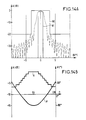
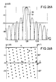
- FIG. 5A presents the emission diagram, obtained with a uniform illumination represented in FIG. 5B (with 128 patch lines), that is to say equi-amplitude (the HPA amplifiers all operate at the same level) and equiphase (to have a fine lobe).
- FIG. 6A presents the reception diagram: the illumination represented in FIG. 6B is always equiphase; a suitable amplitude weighting makes it possible to lower the first secondary lobes relative to the following.
- the curves 80 and 81 shown in parts A of the figures are respectively an outside template, and a corresponding inside template which are imposed.
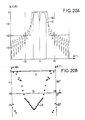
- FIGS. 8A, 9A and 10 respectively represent reception, emission and emission-reception diagrams. They show that a suitable quantization step, eight levels (therefore three bits) is sufficient to have a law of illumination in reception similar to the "continuous control" case (FIG. 6), and a diagram of similar quality. With 128 omnidirectional sources, 0.57 ⁇ apart, we obtain an overall illumination efficiency that is still just as good (-0.16 dB).
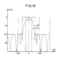
- FIGS. 11A, 12A and 13 which respectively represent transmission, reception, and transmission / reception diagrams, show that even if the number of antenna feed points is greatly reduced (and therefore amplitude controls) and if we maintain a quantization on eight levels, we obtain by the process described above, an equivalent transmission-reception diagram of similar quality.
- it is an active antenna for space SAR of 8.16 meters in length, broken down into 17 48-centimeter sub-panels, which are only amplitude controlled, so as to use identical distributors inside. of all the sub-panels.
- the overall illumination efficiency is slightly worse (-0.18 dB).
- Such a method can be generalized to any number of active modules, beyond a minimum number close to ten on the dimension of the antenna considered.
- This process limits the number of commands to be transmitted to the active modules to the only reconfiguration of the phase shifters: this is in any case necessary for the depointing of the beam, generally linked to its widening. Since the enlargement phase is identical in transmission and reception, the control phase of the phase shifters is moderate.
- the diagram of the enlarged lobe has steeper sides than those of FIG. 16, the discriminating power of the radar is therefore better.
- Some radars only require electronic scanning in one plane, for example the elevation plane in SCAR (Side-looking airbonne radar) or SAR modes.
- FIG. 23 represents a large active antenna (8m32 x 1m91) intended for a space observation radar operating in SAR mode.
- the antenna is broken down into three panels 25, 26 and 27. It has 88 identical horizontal lines 28, as shown in FIG. 24.
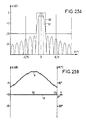
- Each MAER modules 29 are arranged on each horizontal line 28 of radiating elements (here superimposed slot guides 32 and 33, radiating in horizontal polarization, others in vertical polarization). Their non-uniform distribution (closer together in the center) combined with an adjustment of the conductances of the radiating slits to obtain an amplitude law varying linearly in dB from one end to the other, makes it possible to produce a diagram of good quality (FIG. 25).
Landscapes
- Variable-Direction Aerials And Aerial Arrays (AREA)
- Radar Systems Or Details Thereof (AREA)
Applications Claiming Priority (2)
| Application Number | Priority Date | Filing Date | Title |
|---|---|---|---|
| FR9003028 | 1990-03-09 | ||
| FR9003028A FR2659500B1 (fr) | 1990-03-09 | 1990-03-09 | Procede de formation du diagramme d'une antenne active a haut rendement pour radar a balayage electronique et antenne mettant en óoeuvre ce procede. |
Publications (3)
| Publication Number | Publication Date |
|---|---|
| EP0451497A1 true EP0451497A1 (de) | 1991-10-16 |
| EP0451497B1 EP0451497B1 (de) | 1995-12-20 |
| EP0451497B2 EP0451497B2 (de) | 2000-12-20 |
Family
ID=9394571
Family Applications (1)
| Application Number | Title | Priority Date | Filing Date |
|---|---|---|---|
| EP91103216A Expired - Lifetime EP0451497B2 (de) | 1990-03-09 | 1991-03-04 | Verfahren zur Formung des Strahlendiagrammes einer aktiven Radarantenne mit elektronisch gesteuerter Ablenkung, und Antenne dazu |
Country Status (7)
| Country | Link |
|---|---|
| US (1) | US5124712A (de) |
| EP (1) | EP0451497B2 (de) |
| JP (1) | JP2765770B2 (de) |
| CA (1) | CA2037849C (de) |
| DE (1) | DE69115544T3 (de) |
| ES (1) | ES2081379T3 (de) |
| FR (1) | FR2659500B1 (de) |
Cited By (2)
| Publication number | Priority date | Publication date | Assignee | Title |
|---|---|---|---|---|
| JPH05107335A (ja) * | 1991-10-19 | 1993-04-27 | Nec Corp | アクテイブフエーズドアレイレーダ空中線装置 |
| FR2943182A1 (fr) * | 2009-03-10 | 2010-09-17 | Thales Sa | Procede d'ajustement du lobe du diagramme de rayonnement d'une antenne de type reseau. |
Families Citing this family (14)
| Publication number | Priority date | Publication date | Assignee | Title |
|---|---|---|---|---|
| FR2679704B1 (fr) * | 1991-07-26 | 1993-09-24 | Alcatel Espace | Antenne-reseau pour ondes hyperfrequences. |
| JP2560001Y2 (ja) * | 1991-09-04 | 1998-01-21 | 三菱電機株式会社 | 送受信モジュール |
| CA2504222C (en) | 2002-10-22 | 2012-05-22 | Jason A. Sullivan | Robust customizable computer processing system |
| EP1557075A4 (de) | 2002-10-22 | 2010-01-13 | Sullivan Jason | Nicht-peripheres verarbeitungssteuermodul mit verbesserten wärmeableiteigenschaften |
| CA2503793A1 (en) | 2002-10-22 | 2004-05-06 | Jason A. Sullivan | Systems and methods for providing a dynamically modular processing unit |
| GB0526661D0 (en) * | 2005-11-23 | 2006-12-13 | Bae Systems Plc | Array Antenna |
| JP5040549B2 (ja) * | 2007-09-20 | 2012-10-03 | 日本電気株式会社 | 合成開口レーダ及びコンパクト・ポラリメトリsar処理方法、プログラム |
| US9653799B2 (en) * | 2010-11-16 | 2017-05-16 | Raytheon Company | Method and apparatus for controlling sidelobes of an active antenna array |
| WO2012109393A1 (en) | 2011-02-08 | 2012-08-16 | Henry Cooper | High gain frequency step horn antenna |
| WO2012109498A1 (en) | 2011-02-09 | 2012-08-16 | Henry Cooper | Corrugated horn antenna with enhanced frequency range |
| KR102134178B1 (ko) * | 2012-08-09 | 2020-07-16 | 이스라엘 에어로스페이스 인더스트리즈 리미티드 | 피아 식별 시스템 및 방법 |
| WO2014043401A1 (en) * | 2012-09-12 | 2014-03-20 | Wireless Research Development | Wireless antenna communicating system and method |
| US9450309B2 (en) | 2013-05-30 | 2016-09-20 | Xi3 | Lobe antenna |
| US11754706B2 (en) * | 2020-09-17 | 2023-09-12 | Rockwell Collins, Inc. | Agile antenna taper based on weather radar feedback |
Family Cites Families (14)
| Publication number | Priority date | Publication date | Assignee | Title |
|---|---|---|---|---|
| US4052723A (en) * | 1976-04-26 | 1977-10-04 | Westinghouse Electric Corporation | Randomly agglomerated subarrays for phased array radars |
| US4178581A (en) † | 1978-11-03 | 1979-12-11 | The Bendix Corporation | Integrated antenna aperture |
| JPS58100503A (ja) * | 1981-12-09 | 1983-06-15 | Mitsubishi Electric Corp | レ−ダ装置 |
| JPS596784U (ja) * | 1982-07-05 | 1984-01-17 | 三菱電機株式会社 | アクテイブ送受信モジユ−ル |
| US4766437A (en) * | 1983-01-12 | 1988-08-23 | Grumman Aerospace Corporation | Antenna apparatus having means for changing the antenna radiation pattern |
| JPS59157347U (ja) * | 1983-04-08 | 1984-10-22 | 三菱電機株式会社 | 送受信装置 |
| JPS6150278U (de) * | 1984-09-05 | 1986-04-04 | ||
| SE456536B (sv) * | 1985-03-08 | 1988-10-10 | Ericsson Telefon Ab L M | Testanordning i ett radarsystem med en elektriskt syyrd antenn |
| US4724441A (en) * | 1986-05-23 | 1988-02-09 | Ball Corporation | Transmit/receive module for phased array antenna system |
| JPH01500476A (ja) † | 1986-07-29 | 1989-02-16 | ヒユーズ・エアクラフト・カンパニー | 低サイドローブ形ソリッドステートアレイアンテナ装置およびこのアレイアンテナ装置の形成方法 |
| US4791421A (en) * | 1986-09-10 | 1988-12-13 | Westinghouse Electric Corp. | Transmit-receive module for phased-array antennas |
| JPS63175788A (ja) * | 1987-01-16 | 1988-07-20 | Mitsubishi Heavy Ind Ltd | ビ−ム多分割フエ−ズドアレイレ−ダ |
| JP2589811B2 (ja) | 1989-06-30 | 1997-03-12 | 松下電器産業株式会社 | 受信装置 |
| US5017928A (en) * | 1990-08-22 | 1991-05-21 | The United States Of America As Represented By The Secretary Of The Air Force | Low sidelobe array by amplitude edge tapering the edge elements |
-
1990
- 1990-03-09 FR FR9003028A patent/FR2659500B1/fr not_active Expired - Fee Related
-
1991
- 1991-03-04 DE DE69115544T patent/DE69115544T3/de not_active Expired - Lifetime
- 1991-03-04 ES ES91103216T patent/ES2081379T3/es not_active Expired - Lifetime
- 1991-03-04 EP EP91103216A patent/EP0451497B2/de not_active Expired - Lifetime
- 1991-03-06 US US07/665,202 patent/US5124712A/en not_active Expired - Lifetime
- 1991-03-08 CA CA002037849A patent/CA2037849C/fr not_active Expired - Lifetime
- 1991-03-08 JP JP3125606A patent/JP2765770B2/ja not_active Expired - Lifetime
Cited By (2)
| Publication number | Priority date | Publication date | Assignee | Title |
|---|---|---|---|---|
| JPH05107335A (ja) * | 1991-10-19 | 1993-04-27 | Nec Corp | アクテイブフエーズドアレイレーダ空中線装置 |
| FR2943182A1 (fr) * | 2009-03-10 | 2010-09-17 | Thales Sa | Procede d'ajustement du lobe du diagramme de rayonnement d'une antenne de type reseau. |
Also Published As
| Publication number | Publication date |
|---|---|
| EP0451497B1 (de) | 1995-12-20 |
| DE69115544T2 (de) | 1996-05-02 |
| CA2037849A1 (fr) | 1991-09-10 |
| FR2659500B1 (fr) | 1992-05-15 |
| JPH04230881A (ja) | 1992-08-19 |
| DE69115544T3 (de) | 2001-08-09 |
| ES2081379T3 (es) | 1996-03-01 |
| DE69115544D1 (de) | 1996-02-01 |
| JP2765770B2 (ja) | 1998-06-18 |
| CA2037849C (fr) | 1994-09-20 |
| US5124712A (en) | 1992-06-23 |
| FR2659500A1 (fr) | 1991-09-13 |
| EP0451497B2 (de) | 2000-12-20 |
Similar Documents
| Publication | Publication Date | Title |
|---|---|---|
| EP0451497B1 (de) | Verfahren zur Formung des Strahlendiagrammes einer aktiven Radarantenne mit elektronisch gesteuerter Ablenkung, und Antenne dazu | |
| CA2037841C (fr) | Systeme d'antenne imprimee active a haut rendement pour radar spatial agile | |
| EP2532050B1 (de) | Bordinterne direktionale flachplattenantenne, fahrzeug mit einer solchen antenne und satellitentelekommunikationssystem mit einem solchen fahrzeug | |
| EP2532046B1 (de) | Flachplatten-abtastantenne für landfahrzeuganwendung, fahrzeug mit einer solchen antenne und satellitentelekommunikationssystem mit solch einem fahrzeug | |
| EP0600799B1 (de) | Aktive Antenne mit variabler Polarisations-Synthese | |
| CA2685708A1 (fr) | Antenne a partage de sources et procede d'elaboration d'une antenne a partage de sources pour l'elaboration de multi-faisceaux | |
| EP3176875B1 (de) | Aufbau einer aktiven hybriden rekonfigurierbaren strahlbildungsantenne | |
| FR3062523A1 (fr) | Antenne elementaire a dispositif rayonnant planaire | |
| EP0288988B1 (de) | Adaptives Antennensystem für Hochfrequenz, insbesondere für den UHF-Bereich | |
| EP1188202B1 (de) | Anordnung zur übertragung und/oder zum empfang von signalen | |
| EP1533866B1 (de) | Adaptive Phasengesteuerte Gruppenantenne mit digitaler Keulenformung | |
| EP1351333A2 (de) | Adaptive Gruppenantenne und Radar mit einer solchen Antenne | |
| EP4020834B1 (de) | Vorrichtung zur steuerung einer aktiven antenne mit abtastung | |
| EP0638956A1 (de) | Aktive Antenne mit elektronischem Absuchen in Azimut und Elevation, insbesondere für Mikrowellen-Abbildung mittels Satellit | |
| EP1107359A1 (de) | Strahlungsquelle für eine Sende-/Empfangsantenne an Bord eines Satelliten | |
| FR2930844A1 (fr) | Antenne rf d'emission et/ou de reception comportant des elements rayonnants excites par couplage electromagnetique sans contact | |
| FR2717312A1 (fr) | Emetteur directionnel orientable. | |
| Wang et al. | Multifunctional Wideband Digital Metasurface for Secure Electromagnetic Manipulation in S-Band | |
| EP3506429A1 (de) | Quasioptischer strahlformer, entsprechende elementarantenne und plattform, entsprechendes antennensystem und kommunikationsverfahren | |
| FR3152094A1 (fr) | Système antennaire et antenne réseau correspondante | |
| EP0156685B1 (de) | Verfahren gegen Störungen für eine Antennengruppe und mit einem solchen Verfahren arbeitende Antenne | |
| Forrest | An array of possibilities for future antenna systems | |
| EP3155689A1 (de) | Flachantenne zur satellitenkommunikation | |
| FR2723264A1 (fr) | Antenne de radar de type reseau fixe a pointage omnidirectionnel en azimut et a formation de faisceaux par le calcul | |
| FR3077695A1 (fr) | Dispositif et procede d'emission/reception de signaux radioelectriques |
Legal Events
| Date | Code | Title | Description |
|---|---|---|---|
| PUAI | Public reference made under article 153(3) epc to a published international application that has entered the european phase |
Free format text: ORIGINAL CODE: 0009012 |
|
| AK | Designated contracting states |
Kind code of ref document: A1 Designated state(s): DE ES FR GB IT SE |
|
| 17P | Request for examination filed |
Effective date: 19920330 |
|
| 17Q | First examination report despatched |
Effective date: 19940218 |
|
| GRAA | (expected) grant |
Free format text: ORIGINAL CODE: 0009210 |
|
| AK | Designated contracting states |
Kind code of ref document: B1 Designated state(s): DE ES FR GB IT SE |
|
| REF | Corresponds to: |
Ref document number: 69115544 Country of ref document: DE Date of ref document: 19960201 |
|
| ITF | It: translation for a ep patent filed | ||
| REG | Reference to a national code |
Ref country code: ES Ref legal event code: FG2A Ref document number: 2081379 Country of ref document: ES Kind code of ref document: T3 |
|
| GBT | Gb: translation of ep patent filed (gb section 77(6)(a)/1977) |
Effective date: 19960314 |
|
| PLBQ | Unpublished change to opponent data |
Free format text: ORIGINAL CODE: EPIDOS OPPO |
|
| PLBI | Opposition filed |
Free format text: ORIGINAL CODE: 0009260 |
|
| PLBF | Reply of patent proprietor to notice(s) of opposition |
Free format text: ORIGINAL CODE: EPIDOS OBSO |
|
| 26 | Opposition filed |
Opponent name: DAIMLER-BENZ AEROSPACE AG SENSORSYSTEME Effective date: 19960920 Opponent name: HOLLANDSE SIGNAALAPPARATEN B.V. Effective date: 19960912 |
|
| PLBF | Reply of patent proprietor to notice(s) of opposition |
Free format text: ORIGINAL CODE: EPIDOS OBSO |
|
| PLBF | Reply of patent proprietor to notice(s) of opposition |
Free format text: ORIGINAL CODE: EPIDOS OBSO |
|
| RAP2 | Party data changed (patent owner data changed or rights of a patent transferred) |
Owner name: ALCATEL SPACE INDUSTRIES |
|
| PLAW | Interlocutory decision in opposition |
Free format text: ORIGINAL CODE: EPIDOS IDOP |
|
| PLAW | Interlocutory decision in opposition |
Free format text: ORIGINAL CODE: EPIDOS IDOP |
|
| PUAH | Patent maintained in amended form |
Free format text: ORIGINAL CODE: 0009272 |
|
| STAA | Information on the status of an ep patent application or granted ep patent |
Free format text: STATUS: PATENT MAINTAINED AS AMENDED |
|
| 27A | Patent maintained in amended form |
Effective date: 20001220 |
|
| AK | Designated contracting states |
Kind code of ref document: B2 Designated state(s): DE ES FR GB IT SE |
|
| PGFP | Annual fee paid to national office [announced via postgrant information from national office to epo] |
Ref country code: SE Payment date: 20010305 Year of fee payment: 11 |
|
| PGFP | Annual fee paid to national office [announced via postgrant information from national office to epo] |
Ref country code: ES Payment date: 20010316 Year of fee payment: 11 |
|
| ITF | It: translation for a ep patent filed | ||
| GBTA | Gb: translation of amended ep patent filed (gb section 77(6)(b)/1977) | ||
| PG25 | Lapsed in a contracting state [announced via postgrant information from national office to epo] |
Ref country code: ES Free format text: LAPSE BECAUSE OF FAILURE TO SUBMIT A TRANSLATION OF THE DESCRIPTION OR TO PAY THE FEE WITHIN THE PRESCRIBED TIME-LIMIT Effective date: 20010520 |
|
| REG | Reference to a national code |
Ref country code: GB Ref legal event code: IF02 |
|
| PG25 | Lapsed in a contracting state [announced via postgrant information from national office to epo] |
Ref country code: SE Free format text: THE PATENT HAS BEEN ANNULLED BY A DECISION OF A NATIONAL AUTHORITY Effective date: 20020330 |
|
| PLAB | Opposition data, opponent's data or that of the opponent's representative modified |
Free format text: ORIGINAL CODE: 0009299OPPO |
|
| PGFP | Annual fee paid to national office [announced via postgrant information from national office to epo] |
Ref country code: FR Payment date: 20100324 Year of fee payment: 20 Ref country code: IT Payment date: 20100313 Year of fee payment: 20 |
|
| PGFP | Annual fee paid to national office [announced via postgrant information from national office to epo] |
Ref country code: GB Payment date: 20100303 Year of fee payment: 20 |
|
| PGFP | Annual fee paid to national office [announced via postgrant information from national office to epo] |
Ref country code: DE Payment date: 20100312 Year of fee payment: 20 |
|
| REG | Reference to a national code |
Ref country code: DE Ref legal event code: R071 Ref document number: 69115544 Country of ref document: DE |
|
| REG | Reference to a national code |
Ref country code: GB Ref legal event code: PE20 Expiry date: 20110303 |
|
| PG25 | Lapsed in a contracting state [announced via postgrant information from national office to epo] |
Ref country code: GB Free format text: LAPSE BECAUSE OF EXPIRATION OF PROTECTION Effective date: 20110303 |
|
| PG25 | Lapsed in a contracting state [announced via postgrant information from national office to epo] |
Ref country code: DE Free format text: LAPSE BECAUSE OF EXPIRATION OF PROTECTION Effective date: 20110304 |