EP0451523A2 - Interface pour connecter un ordinateur à un appareil numérique de télécommunication - Google Patents
Interface pour connecter un ordinateur à un appareil numérique de télécommunication Download PDFInfo
- Publication number
- EP0451523A2 EP0451523A2 EP91103816A EP91103816A EP0451523A2 EP 0451523 A2 EP0451523 A2 EP 0451523A2 EP 91103816 A EP91103816 A EP 91103816A EP 91103816 A EP91103816 A EP 91103816A EP 0451523 A2 EP0451523 A2 EP 0451523A2
- Authority
- EP
- European Patent Office
- Prior art keywords
- computer
- circuit arrangement
- power supply
- arrangement according
- interface
- Prior art date
- Legal status (The legal status is an assumption and is not a legal conclusion. Google has not performed a legal analysis and makes no representation as to the accuracy of the status listed.)
- Withdrawn
Links
Images

Classifications
-
- H—ELECTRICITY
- H04—ELECTRIC COMMUNICATION TECHNIQUE
- H04Q—SELECTING
- H04Q11/00—Selecting arrangements for multiplex systems
- H04Q11/04—Selecting arrangements for multiplex systems for time-division multiplexing
- H04Q11/0428—Integrated services digital network, i.e. systems for transmission of different types of digitised signals, e.g. speech, data, telecentral, television signals
- H04Q11/0435—Details
- H04Q11/0471—Terminal access circuits
-
- G—PHYSICS
- G06—COMPUTING OR CALCULATING; COUNTING
- G06F—ELECTRIC DIGITAL DATA PROCESSING
- G06F13/00—Interconnection of, or transfer of information or other signals between, memories, input/output devices or central processing units
- G06F13/38—Information transfer, e.g. on bus
- G06F13/382—Information transfer, e.g. on bus using universal interface adapter
- G06F13/385—Information transfer, e.g. on bus using universal interface adapter for adaptation of a particular data processing system to different peripheral devices
-
- H—ELECTRICITY
- H04—ELECTRIC COMMUNICATION TECHNIQUE
- H04M—TELEPHONIC COMMUNICATION
- H04M1/00—Substation equipment, e.g. for use by subscribers
- H04M1/253—Telephone sets using digital voice transmission
-
- H—ELECTRICITY
- H04—ELECTRIC COMMUNICATION TECHNIQUE
- H04Q—SELECTING
- H04Q2213/00—Indexing scheme relating to selecting arrangements in general and for multiplex systems
- H04Q2213/031—PCM
-
- H—ELECTRICITY
- H04—ELECTRIC COMMUNICATION TECHNIQUE
- H04Q—SELECTING
- H04Q2213/00—Indexing scheme relating to selecting arrangements in general and for multiplex systems
- H04Q2213/08—Power supply
-
- H—ELECTRICITY
- H04—ELECTRIC COMMUNICATION TECHNIQUE
- H04Q—SELECTING
- H04Q2213/00—Indexing scheme relating to selecting arrangements in general and for multiplex systems
- H04Q2213/093—Personal computer
-
- H—ELECTRICITY
- H04—ELECTRIC COMMUNICATION TECHNIQUE
- H04Q—SELECTING
- H04Q2213/00—Indexing scheme relating to selecting arrangements in general and for multiplex systems
- H04Q2213/096—Digital subscriber terminal
Definitions
- the invention relates to a circuit arrangement for connecting a computer having its own power supply device to a digital telecommunication device, in particular a telephone device with an internal bus system, which has an interface for the basic connection with two useful and one data / signaling channel for connection to a digital Telecommunication system and, inter alia, a channel switch for distributing or merging the useful channel information to / from a codec / filter or to / from an interface for connecting external devices, the computer being provided with a corresponding connection interface.
- the basic connection of a digital telecommunications switching system has two useful channels with 64 kbit / s each and a data / signaling channel with 16 kbit / s.
- the V.24 interface on the other hand, only allows the transmission of a maximum of 19.2 kbit / s.
- the object of the invention is to provide a circuit arrangement which enables the connection of such a computer to a digital telephone terminal, with higher data transmission rates per unit time being possible.
- This object is achieved in that the computer is connected to a first pair of lines for transmitting the useful channel information in one of both directions and to the internal bus system of the telecommunications terminal.
- the transmission of the useful signal information can be controlled via the channel switch of the digital telecommunication terminal, while the computer, like other devices of the telecommunication terminal, is connected to the internal bus system of the same.
- the connected computer is thus treated as a separate device of the telecommunications terminal, i.e. that in certain applications it is not necessary to operate the computer via its input keyboard.
- a further development of the invention consists in that the circuit arrangement is supplied with power from the computer.
- the circuit arrangement does not place an additional load on the power supply device of the digital telecommunications terminal.
- a further development of the invention consists in that the power supply device or an additional auxiliary power supply device of the computer can be switched on and off at the instigation of the digital telecommunications terminal.
- the computer can also be used when it is not being operated or is not switched on.
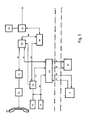
- the digital telephone terminal F is connected to a digital switching system (not shown) via the base connection BA, the base connection BA as a so-called S o interface with the full duplex transmission of two user and one data / signaling channel each with 64 kbit / s or 16 kbit / s can be formed.
- the interface circuit SS serves on the one hand for the electrical isolation of the Connection line of the base connection BA and to provide the supply voltage fed in via the connection line BA from the digital switching center for the power supply SG of the digital telephone terminal F.
- the power supply unit SG supplies all the facilities of the telephone terminal F with the exception of the device PS, which will be discussed in more detail below .
- the digital connection unit DA has the task of channel-dividing the data stream arriving from the interface circuit SS onto the line BSL for the two user channels and the data / signaling information onto the line SL, or of the information arriving on the lines concerned into a common data stream for forwarding to assemble the interface circuit SS.
- the useful channel information is fed to the channel switch KS, which has the task of switching the useful channel information to the line BS or to the line BL.
- the channel switch KS is also able to route useful channel information from the line BS to the line BL.
- the corresponding control commands are received by the channel switch KS from the control device ST of the telephone terminal F, which is also supplied with the data / signaling channel information from the digital connection device DA or which supplies the corresponding data / signaling channel information for the digital connection device DA generated and fed via the line SL.
- a codec / filter CF is connected to the line BS, in which the digital speech information transmitted via a user channel is converted into analog signals which are fed to the electronic speech circuit SK, Likewise, in the codec / filter, the analog voice signals coming from the electronic speech circuit SK are converted into digital voice signals for transmission to the line BS, so that they can be transmitted via a user channel.
- the handset HA with the speech and hearing capsule of the telephone terminal F is connected to the electronic speech circuit SK.
- the display device AZ and input keyboard TA are connected to the control device ST of the telephone terminal F via an internal bus system IB, which can be designed as a so-called I2C bus.
- the internal bus system IB is used, for example, to transmit the key information of the input keyboard TA to the control device ST and to transmit information from the control device ST to the display device AZ, which are displayed there optically.
- the information of the data / signaling channel is transmitted to the control device ST, where it is evaluated in the same.
- the evaluation for example, depending on the information transmitted via the data / signaling channel, corresponding displays on the optical display device AZ can be initiated by the control device ST. It is also possible, depending on key presses on the input keyboard TA, to generate corresponding information in the control device ST which is transmitted to the exchange via the data / signaling channel.
- the control of the channel switch KS is also conceivable as a function of information that is via the data / signaling channel or via the internal bus system IB have been transmitted to the control device ST.
- the digital telephone terminal F has a special interface circuit PS. This is connected to the line BL for transmitting the useful channel information in both directions, to the internal bus system IB and to the control line STL, which will be discussed in more detail below.
- the computer PC is equipped with an interface circuit SP, which is connected to the interface circuit PS via the lines B for transmitting the useful channel information in both directions and with the line BI for transmitting the information of the internal bus system IB in both directions.
- the structure and function of the interface circuit SP of the computer PC will not be discussed further in the context of this description, and reference is made to the printed ISDN report no.
- the task of the interface circuit SP is generally to supply the useful channel information for processing within the computer PC or to record the information generated there for the useful channel or channels and the information intended for the computer PC, which about the internal bus system IB have been transmitted to the computer PC in such a way that they trigger the corresponding functions there or to supply the control information generated in the computer PC to the internal bus system IB.
- the power supply to the interface circuit PS of the digital telephone terminal F takes place via the line SV from the power supply device S of the computer PC, and with regard to the power supply a certain function in the computer PC can be initiated via the line SG by the control device ST of the digital telephone terminal F.
- the computer PC can work, for example, as an answering machine, either immediately as a result of a previously entered key information or after a certain time when an incoming call comes from the control device ST, the relevant user channel via the channel switch KS is switched through to the interface circuit SP of the computer PC, which on the one hand enables the transmission of an announcement text contained in the computer PC to the called subscriber and the storage of the voice information arriving from the calling subscriber and transmitted via the user channel in the computer PC.
- memory areas for the answering machine function are reserved for this purpose, for example on a hard drive, which contain the announcement texts in the form of PCM data words and the PCM data words of the caller to record spoken texts.
- the computer PC receives the arrival of the signaling information announcing a call, which was transmitted via the data / signaling channel from the switching center to the telephone terminal F, at the instigation of Control device ST, via the internal data bus IB, provides corresponding information which prompts the reading of the announcement text and the subsequent storage of the voice information arriving from the calling subscriber in the computer PC.
- a further function of the computer PC can be to encrypt or decrypt voice information from the switching center before it is transmitted via a user channel to the switching center or after it has arrived on a user channel.
- the channel switch KS is prompted by the control device ST on the basis of corresponding key inputs to redirect the speech signals generated by the codec / filter CF from the line BS to the line BL, so that these are first fed to the computer PC and encrypted there.
- the encrypted voice signals are then transmitted again via line BL back to channel switch KS, which forwards them to line BSL for forwarding to the exchange.
- the voice signals arriving from the exchange which were transmitted via a user channel, are first fed to the computer PC and then, after decryption, passed on to the codec / filter CF in the manner already described.
- the computer PC received a message from the control device ST via the internal bus system IB that the voice signals arriving via line B had to be encrypted or decrypted in the computer PC.
- the "encrypt or decrypt" function can be initiated, for example, by pressing an appropriate button or also by corresponding signaling information which has been transmitted by the subscriber's subscriber station. Part of this signaling information can also contain the information for the basic key setting and other key-related data.
- the computer PC can of course also be used in the context of the known data applications, including the reception of fax documents and for the reception and transmission of telex and teletex messages.
- the establishment of the connection can also be controlled with the aid of the computer PC, in that it contains subscriber directories for the various services, which are called up either via the input keyboard TA of the telephone terminal F, if this has an alphanumeric input keyboard, or via the input keyboard of the computer PC can.
- the key information is transmitted to the computer PC via the internal bus system IB, while in both cases the signaling information for establishing the connection is transmitted from the computer PC via the internal bus system IB to the control device ST, which is then passed on to the switching center over the data signaling channel prompted in the manner already described.
- the circuit arrangement of the interface circuit PS can be designed as a self-contained arrangement in the form of a module, the module forming part of the digital telephone device F.
- the internal bus system IB is connected to a converter U, which converts the incoming information on line L3 to the computer PC or the information arriving on line L4 from there for transmission to the internal bus system IB.
- the converter U therefore converts from a bidirectional transmission link to a unidirectional transmission link or vice versa.
- the information that is transmitted via one or both user channels arrives on line BL and is passed on to line L1 to the computer PC, or the information arriving from there on line L2 is sent to line BL for transmission to one User channel passed on.
- the optocouplers K1, K2, K4 and K5 are looped into the lines mentioned.
- Amplifiers V1, V2, V4 and V5 are provided to amplify the outgoing and incoming signals.
- the interface circuit PS is supplied with power via the line SV or more precisely, in the normal case via the line U P.
- the voltage regulator SR sets the supply voltage from the computer PC down to 9 volts to the required supply voltage U PC of 5 volts.
- the amplifiers V1-V5 and the optocouplers K1-K5 are supplied with this voltage U P.
- a DC / DC voltage converter is provided, which generates the voltage U DC for supplying the devices of the interface circuit PS operated on the apparatus side.
- the supply voltage U ST is also connected to the interface circuit PS, but it is not effective since it is blocked by the diode D2.
- the earth D of the telephone terminal F is connected, while on the computer side the earth GND of the computer PC is connected.
- the presence of the supply voltage U P of the computer PC in the interface circuit PS is monitored by the monitoring device UE and, in the absence of the same, the lines BL, STL and the internal bus system IB are disconnected, either by integrated switching devices in the devices PLC and U or via special switching devices S1 and S2, which are looped into the lines BL.
- the computer PC It is possible to equip the computer PC with a special power supply device which supplies the supply voltage U NOT .
- This particular power supply device can be switched on via the line STL by the control device ST of the digital telephone set F (FIG. 1).
- This signal reaches the power supply control device SPS and causes the optocoupler K3 and the amplifier V3 to send a signal on the line SG to the computer PC.
- the power supply control device PLC may not be blocked by the monitoring device UE if the supply voltage U P is not present via the line EN, this is indicated by the dashed line.
- the diodes D3 and D4 serve to decouple the two voltage supplies U P and U NOT .
- the monitoring device UE is likewise galvanically isolated in terms of input and output.
- the line BL consists of two lines, one line being operated in the forward direction and the other in the reverse direction.
- this also applies to the lines BS shown in FIG. 1 and possibly also BSL.
- This makes the structure of the channel switch KS simpler and clearer, which incidentally is also used to derive the internal clocks from the data stream arriving from the exchange (FIG. 1).
- the monitoring device UE not only monitors the presence of the supply voltage U P of the computer PC, but also the output voltage U DC of the voltage converter SW and the presence of the supply voltage U ST of the telephone terminal F. It should be noted that if the latter two voltages fail in In any case, the signal EN becomes effective in all of the devices mentioned, even if the supply voltage U P of the computer PC is present. In this way, the function of the voltage converter SW is monitored and unwanted operating states are avoided.
- the line EN (shown in dashed lines) can also be routed to the telephone terminal F, in which case it is possible to monitor the signal EN in the same and to trigger the switching on of the supply voltage U NOT in the computer PC as a function of this signal.
Landscapes
- Engineering & Computer Science (AREA)
- Theoretical Computer Science (AREA)
- Signal Processing (AREA)
- Physics & Mathematics (AREA)
- General Engineering & Computer Science (AREA)
- General Physics & Mathematics (AREA)
- Computer Networks & Wireless Communication (AREA)
- Telephonic Communication Services (AREA)
Applications Claiming Priority (2)
| Application Number | Priority Date | Filing Date | Title |
|---|---|---|---|
| DE4008667 | 1990-03-17 | ||
| DE19904008667 DE4008667A1 (de) | 1990-03-17 | 1990-03-17 | Schaltungsanordnung zum anschluss eines rechners an einem digitalen fernsprechendgeraet |
Publications (2)
| Publication Number | Publication Date |
|---|---|
| EP0451523A2 true EP0451523A2 (fr) | 1991-10-16 |
| EP0451523A3 EP0451523A3 (en) | 1992-09-09 |
Family
ID=6402484
Family Applications (1)
| Application Number | Title | Priority Date | Filing Date |
|---|---|---|---|
| EP19910103816 Withdrawn EP0451523A3 (en) | 1990-03-17 | 1991-03-13 | Interface for connecting a computer to a digital telecommunications terminal |
Country Status (2)
| Country | Link |
|---|---|
| EP (1) | EP0451523A3 (fr) |
| DE (1) | DE4008667A1 (fr) |
Cited By (5)
| Publication number | Priority date | Publication date | Assignee | Title |
|---|---|---|---|---|
| EP0541118A1 (fr) * | 1991-11-06 | 1993-05-12 | Sedlbauer Aktiengesellschaft | Dispositif de commande pour le transfert de données entre un réseau téléphonique numérique et un terminal à commande par processeur |
| EP0541119A1 (fr) * | 1991-11-06 | 1993-05-12 | Sedlbauer Aktiengesellschaft | Dispositif de commande pour le transfert de données entre un réseau téléphonique numérique et un terminal à commande par processeur |
| DE4241857A1 (de) * | 1992-12-11 | 1994-06-16 | Thomson Brandt Gmbh | Rundfunkempfänger mit einem Zusatzdatendecoder |
| WO1995001036A1 (fr) * | 1993-06-24 | 1995-01-05 | Siemens Rolm Communications Inc. | Adaptateur de bus d'option s'utilisant avec un telephone numerique |
| EP0774851A3 (fr) * | 1995-11-17 | 2003-01-02 | Tenovis GmbH & Co. KG | Méthode pour la coopération avec un ordinateur externe et un terminal de télécommunication |
Families Citing this family (8)
| Publication number | Priority date | Publication date | Assignee | Title |
|---|---|---|---|---|
| DE4239656C1 (de) * | 1992-11-26 | 1994-01-27 | Grundig Emv | Modulare Teilnehmereinrichtung |
| DE4409669C2 (de) * | 1994-03-15 | 1997-04-24 | Elmeg Kommunikationstech | Adapter für den Anschluß mindestens eines analogen Fernsprechendgerätes an ein digitales Telefonnetz |
| DE4431084C2 (de) * | 1994-09-01 | 1999-01-07 | Voigt Hans Joachim | Modul zur Verbindung von Informationsverarbeitungsgeräten mit Kommunikationsnetzen |
| CA2158408C (fr) * | 1995-09-15 | 1998-12-08 | Mitel Networks Corporation | Architecture d'interface robuste commandee par ordinateur pour la telephonie |
| DE19619994A1 (de) * | 1996-05-17 | 1997-11-20 | Deutsche Telekom Ag | Telefonumschalter |
| DE19636951A1 (de) * | 1996-09-11 | 1998-03-12 | Siemens Ag | Telekommunikationsnetz-Abschlußeinheit |
| CN1130949C (zh) | 1997-09-22 | 2003-12-10 | 西门子公司 | 通信系统 |
| DE19809803A1 (de) * | 1998-03-09 | 1999-09-16 | Bosch Gmbh Robert | Endgerätekombination für eine Vermittlungsanlage |
Family Cites Families (1)
| Publication number | Priority date | Publication date | Assignee | Title |
|---|---|---|---|---|
| EP0391157A3 (fr) * | 1989-04-03 | 1991-09-18 | Siemens Aktiengesellschaft | Module d'interface |
-
1990
- 1990-03-17 DE DE19904008667 patent/DE4008667A1/de active Granted
-
1991
- 1991-03-13 EP EP19910103816 patent/EP0451523A3/de not_active Withdrawn
Cited By (6)
| Publication number | Priority date | Publication date | Assignee | Title |
|---|---|---|---|---|
| EP0541118A1 (fr) * | 1991-11-06 | 1993-05-12 | Sedlbauer Aktiengesellschaft | Dispositif de commande pour le transfert de données entre un réseau téléphonique numérique et un terminal à commande par processeur |
| EP0541119A1 (fr) * | 1991-11-06 | 1993-05-12 | Sedlbauer Aktiengesellschaft | Dispositif de commande pour le transfert de données entre un réseau téléphonique numérique et un terminal à commande par processeur |
| DE4241857A1 (de) * | 1992-12-11 | 1994-06-16 | Thomson Brandt Gmbh | Rundfunkempfänger mit einem Zusatzdatendecoder |
| WO1995001036A1 (fr) * | 1993-06-24 | 1995-01-05 | Siemens Rolm Communications Inc. | Adaptateur de bus d'option s'utilisant avec un telephone numerique |
| AU691185B2 (en) * | 1993-06-24 | 1998-05-14 | Siemens Rolm Communications Inc. | Option bus adapter for use with a digital telephone |
| EP0774851A3 (fr) * | 1995-11-17 | 2003-01-02 | Tenovis GmbH & Co. KG | Méthode pour la coopération avec un ordinateur externe et un terminal de télécommunication |
Also Published As
| Publication number | Publication date |
|---|---|
| EP0451523A3 (en) | 1992-09-09 |
| DE4008667C2 (fr) | 1992-01-23 |
| DE4008667A1 (de) | 1991-09-19 |
Similar Documents
| Publication | Publication Date | Title |
|---|---|---|
| EP0668706B1 (fr) | Terminal de réseau | |
| DE4008667C2 (fr) | ||
| DE19636819C2 (de) | Rechnergesteuerter Telefonapparat | |
| DE3405286A1 (de) | Vermittlungssystem zwischen periferen schaltkreisen | |
| DE4131062C1 (fr) | ||
| DE3010701C2 (de) | Teilnehmer-Endeinrichtung für ein digitales Nachrichtenübermittlungssystem | |
| DE3224459A1 (de) | Schaltungsanordnung fuer fernmeldevermittlungsanlagen, insbesondere fernsprechvermittlungsanlagen, mit konzentratoren mit insel-vermittlungsbetrieb bei funktionsausfall der konzentratorsteuerleitungen | |
| DE4226332A1 (de) | Verfahren und Vorrichtung zum schnellen Datenaustausch | |
| EP0359156A2 (fr) | Interface d'un réseau et terminal téléphonique | |
| EP0691796B1 (fr) | Dispositif de terminaison de réseau | |
| AT396535B (de) | Nachrichtenübertragungssystem, insbesondere telefonsystem | |
| DE3542969A1 (de) | Verfahren zur aktivierung von merkmalen in digital durchschaltenden fernmelde-, insbesondere fernsprechvermittlungsanlagen | |
| DE3824190A1 (de) | Verfahren zum gegenseitigen datenaustausch zwischen einer kommunikations-vermittlungsanlage und einer personalzeit-erfassungsanlage | |
| DE3405011C1 (de) | Schaltungsanordnung zum Betreiben von zweiadrigen, digitalen Anschluß- und/oder Verbindungsleitungen an einer Fernmeldevermittlungsanlage | |
| EP0440062A2 (fr) | Reconnaissance d'état de connection dans un central de communication privé À large bande | |
| EP0708575A2 (fr) | Terminaison de RNIS | |
| EP0024617A1 (fr) | Système de télécommunication numérique | |
| DE4121195C2 (fr) | ||
| EP0503412B1 (fr) | Installation téléphonique à lignes multiples commandée par touches pour la communication orale alternative ou simultanée par haut-parleur | |
| DE2137777C (de) | Schaltungsanordnung fur Fernsprech anlagen mit zusatzlichem Datenverkehr | |
| DE3643614C2 (de) | Modular aufgebautes Kommunikationssystem | |
| CH659927A5 (de) | Teilnehmerleitungs-endausruestung. | |
| DE2422504A1 (de) | Nachrichtenuebertragungssystem | |
| DE3314596C2 (de) | Verfahren zur Einspeisung von Hörtönen und zur Realisierung von Mehrfachverbindungen in zeitmultiplex digital durchschaltenden Fernmelde-, insbesondere Fernsprechanlagen | |
| DE3625857A1 (de) | Kommunikationsnebenstellenanlage fuer sprach- und/oder datenkommunikationsdienste |
Legal Events
| Date | Code | Title | Description |
|---|---|---|---|
| PUAI | Public reference made under article 153(3) epc to a published international application that has entered the european phase |
Free format text: ORIGINAL CODE: 0009012 |
|
| AK | Designated contracting states |
Kind code of ref document: A2 Designated state(s): AT BE CH FR GB IT LI LU NL |
|
| PUAL | Search report despatched |
Free format text: ORIGINAL CODE: 0009013 |
|
| AK | Designated contracting states |
Kind code of ref document: A3 Designated state(s): AT BE CH FR GB IT LI LU NL |
|
| 17P | Request for examination filed |
Effective date: 19920805 |
|
| RAP3 | Party data changed (applicant data changed or rights of an application transferred) |
Owner name: TELENORMA GMBH |
|
| STAA | Information on the status of an ep patent application or granted ep patent |
Free format text: STATUS: THE APPLICATION HAS BEEN WITHDRAWN |
|
| 17Q | First examination report despatched |
Effective date: 19940927 |
|
| 18W | Application withdrawn |
Withdrawal date: 19941020 |