EP0451581B1 - Transporteur pour abattoirs ou entrepÔts frigorifiques pour la conservation de la viande - Google Patents
Transporteur pour abattoirs ou entrepÔts frigorifiques pour la conservation de la viande Download PDFInfo
- Publication number
- EP0451581B1 EP0451581B1 EP91104563A EP91104563A EP0451581B1 EP 0451581 B1 EP0451581 B1 EP 0451581B1 EP 91104563 A EP91104563 A EP 91104563A EP 91104563 A EP91104563 A EP 91104563A EP 0451581 B1 EP0451581 B1 EP 0451581B1
- Authority
- EP
- European Patent Office
- Prior art keywords
- meat
- conveyor
- tubular track
- drivers
- track
- Prior art date
- Legal status (The legal status is an assumption and is not a legal conclusion. Google has not performed a legal analysis and makes no representation as to the accuracy of the status listed.)
- Expired - Lifetime
Links
- 235000013372 meat Nutrition 0.000 title claims abstract description 28
- 239000000969 carrier Substances 0.000 description 4
- 229910000831 Steel Inorganic materials 0.000 description 3
- 230000002349 favourable effect Effects 0.000 description 3
- 239000010959 steel Substances 0.000 description 3
- 238000003307 slaughter Methods 0.000 description 2
- 230000004308 accommodation Effects 0.000 description 1
- 230000007704 transition Effects 0.000 description 1
Images
Classifications
-
- A—HUMAN NECESSITIES
- A22—BUTCHERING; MEAT TREATMENT; PROCESSING POULTRY OR FISH
- A22C—PROCESSING MEAT, POULTRY, OR FISH
- A22C15/00—Apparatus for hanging-up meat or sausages
- A22C15/003—Hooks or the like specially adapted for meat or hams or part of carcasses
-
- A—HUMAN NECESSITIES
- A22—BUTCHERING; MEAT TREATMENT; PROCESSING POULTRY OR FISH
- A22B—SLAUGHTERING
- A22B7/00—Slaughterhouse arrangements
- A22B7/001—Conveying arrangements
- A22B7/004—Rails for conveying suspended carcasses, e.g. configurations, connections
-
- B—PERFORMING OPERATIONS; TRANSPORTING
- B65—CONVEYING; PACKING; STORING; HANDLING THIN OR FILAMENTARY MATERIAL
- B65G—TRANSPORT OR STORAGE DEVICES, e.g. CONVEYORS FOR LOADING OR TIPPING, SHOP CONVEYOR SYSTEMS OR PNEUMATIC TUBE CONVEYORS
- B65G19/00—Conveyors comprising an impeller or a series of impellers carried by an endless traction element and arranged to move articles or materials over a supporting surface or underlying material, e.g. endless scraper conveyors
- B65G19/02—Conveyors comprising an impeller or a series of impellers carried by an endless traction element and arranged to move articles or materials over a supporting surface or underlying material, e.g. endless scraper conveyors for articles, e.g. for containers
- B65G19/025—Conveyors comprising an impeller or a series of impellers carried by an endless traction element and arranged to move articles or materials over a supporting surface or underlying material, e.g. endless scraper conveyors for articles, e.g. for containers for suspended articles
Definitions
- the invention relates to a slaughterhouse or cold store conveyor for conveying meat hooks along a pipe run, with a conveyor chain which has downwardly projecting drivers which are laterally offset with respect to the pipe run for engaging behind the meat hooks, characterized in that the drivers are each one of the Have a tubular extension indicating a lateral extension for engaging behind the respective meat hook end region located on the side of the tubular track; and that for the side of the carrier facing away from the pipe run a guide rail is provided which is fastened to support brackets with which the pipe run is fastened to a support rail of the conveyor chain.
- a conveyor according to the first part of claim 1 is known from document SU-A1-1 234 301.
- the conveyor according to the invention it is consciously accepted that the meat hooks are gripped behind at a location which is in itself less favorable and, as a result, may be somewhat inclined during conveying relative to a plane perpendicular to the longitudinal axis of the pipe run.
- the area above the pipe run is free of moving drivers. This is particularly favorable where points turn into the side of the pipe run.
- the invention prevents the meat hooks which approach laterally from colliding with drivers as would be conventionally present, which would entail the risk of damage to meat hooks and carriers.
- meat hooks in motion on which large pieces of meat or halves of slaughter hang, have a very considerable kinetic energy.
- the guide rail prevents undesired lateral deflection movements of the drivers.
- the conveyor chain is still arranged higher than the pipe run. This is favorable for the spatial accommodation of the conveyor chain carrier rail, the conveyor chain and the drive of the conveyor.
- the transition to conventional conveyors in slaughterhouse or meat cold store areas, where there are no complications of the type described, in particular no switches, is particularly straightforward.
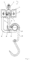
- the conveyor 2 consists, like conventional conveyors, essentially of a carrier rail 4, a conveyor chain 6, pairs of rollers which are spaced along the conveyor chain 6 and roll on the carrier rail 4, and downwardly projecting carriers 8.
- the carrier rail consists of essentially of two U-steel profiles 10, which face each other with their open sides and have a mutual distance.
- the conveyor chain alternately consists of chain links lying essentially horizontally and chain links standing essentially vertically. In each case at a distance of several chain links, fork-shaped roller support parts 12 projecting downward are screwed onto the conveyor chain 6.
- Each roller support part 12 carries on the left outside and on the right outside a roller 14, which rolls on the top of the lower, horizontal leg of the relevant rail half.
- a carrier 8 projecting downward is fastened to each support part 12.
- the support parts 12 protrude upwards and the drivers 8 downwards from the described spacing slot between the steel profiles 10th
- Support brackets 16 are welded to the support rail 4 at a mutual longitudinal distance and have an essentially L-shaped shape.
- a tubular track 18 is fastened on the end regions of the horizontal legs of a plurality of support brackets 16.
- the design is such that the drivers 8 are laterally offset from the tube sheet 18 and protrude approximately to the middle of the tube sheet 18.
- the drivers 8 On their side facing the pipe run 18, the drivers 8 each have a lateral extension 22 pointing towards the pipe run 18, which is arranged somewhat above the center of the pipe run 18. In this way, the extensions 22 can engage behind the end region 24 of the respective meat hook 20 located on the side of the tube track.
- a guide rail 26 in the form of an angle profile made of steel is attached to the horizontal legs of several support brackets 16.
- the guide rail is arranged in such a way that it prevents the drivers 8 from laterally escaping in the direction away from the tubular path 18.
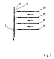
- FIG. 2 illustrates what the situation is when a plurality of lateral tube tracks 28 open one behind the other along the tube track 18 described. This is done by means of so-called slide switches 30, which have a gradient from the relevant lateral tube track 28 to the main tube track 18.
- Slide switches 30 which have a gradient from the relevant lateral tube track 28 to the main tube track 18.
- the meat hooks 20 reach a slide switch 30 and slide there with momentum onto the main tube track 18 because there are no carriers of a conveyor in the area above the main tube track 18, this runs without risk from damage to the hooks 20 and from 8 carriers.
- the meat hooks 20 have properly reached the main tube track 18 from the slide switch 30 in question, they have reached a height position such that their lateral end region 24 can be engaged by a driver extension 22.
- the conveyor chain 6 is an endless chain which is guided around a chain wheel at the beginning and at the end of the conveyor section; one of the two sprockets is driven, usually by means of an electric motor.
- the conveyor is supplied in different, defined lengths depending on requirements and installed in the slaughterhouse or meat cold store.
Landscapes
- Engineering & Computer Science (AREA)
- Life Sciences & Earth Sciences (AREA)
- Food Science & Technology (AREA)
- Wood Science & Technology (AREA)
- Zoology (AREA)
- Mechanical Engineering (AREA)
- Chain Conveyers (AREA)
- Attitude Control For Articles On Conveyors (AREA)
- Pusher Or Impeller Conveyors (AREA)
Claims (2)
- Convoyeur (2) pour abattoir ou pour entrepôt frigorifique à viande, destiné à transporter des crochets à viande (20), le long d'une piste tubulaire (18), avec une chaîne de transport (6), présentant des organes d'entraînement (8) décalés latéralement par rapport à la piste tubulaire (18) et se projetant vers le bas, pour saisir par l'arrière les crochets à viande 20, caractérisé en ce que
les organes d'entraînement (8) présentent chacun un prolongement (22) latéral tourné vers la piste tubulaire (18), destiné à saisir par l'arrière la zone d'extrémité (24) respective du crochet à viande, qui se trouve sur le côté de la piste tubulaire (18);
et en ce qu'un rail de guidage (26), fixé sur des consoles support (16) à l'aide desquels la piste tubulaire (18) est fixée sur un rail support (4) de la chaîne de transport (6), est prévu pour la face, opposée à la piste tubulaire (18), des organes d'entraînement (8). - Convoyeur (2) selon la revendication 1, caractérisé en ce qu'il est prévu dans une zone de la piste tubulaire (18) dans laquelle au moins un aiguillage (30) pénètre dans la piste tubulaire (28), depuis le côté opposé aux organes d'entraînement (8).
Applications Claiming Priority (2)
| Application Number | Priority Date | Filing Date | Title |
|---|---|---|---|
| DE9003620U DE9003620U1 (de) | 1990-03-28 | 1990-03-28 | Schlachthof- oder Fleischkühlhaus-Förderer |
| DE9003620U | 1990-03-28 |
Publications (2)
| Publication Number | Publication Date |
|---|---|
| EP0451581A1 EP0451581A1 (fr) | 1991-10-16 |
| EP0451581B1 true EP0451581B1 (fr) | 1996-07-10 |
Family
ID=6852420
Family Applications (1)
| Application Number | Title | Priority Date | Filing Date |
|---|---|---|---|
| EP91104563A Expired - Lifetime EP0451581B1 (fr) | 1990-03-28 | 1991-03-22 | Transporteur pour abattoirs ou entrepÔts frigorifiques pour la conservation de la viande |
Country Status (3)
| Country | Link |
|---|---|
| EP (1) | EP0451581B1 (fr) |
| AT (1) | ATE140202T1 (fr) |
| DE (2) | DE9003620U1 (fr) |
Families Citing this family (9)
| Publication number | Priority date | Publication date | Assignee | Title |
|---|---|---|---|---|
| DE4138467A1 (de) * | 1991-11-22 | 1993-05-27 | Banss Kg Maschf | Haengefoerderer fuer schlachthoefe oder dergleichen |
| DE4140576A1 (de) * | 1991-12-10 | 1993-06-17 | Pavel Wilfried Maschinen | Foerdervorrichtung fuer auf kleiderbuegel haengend zu transportierende bekleidungsstuecke |
| DE4319164C2 (de) * | 1993-06-09 | 1996-03-21 | Duerkopp Adler Ag | Förderer, insbesondere Stetigförderer für Einzelbügel |
| DE29718307U1 (de) * | 1997-10-15 | 1998-02-19 | Louis Schierholz GmbH & Co KG, 28277 Bremen | Power-and-Free-Schleppförderanlage für stehende Lasten |
| DE29718298U1 (de) * | 1997-10-15 | 1998-06-10 | Louis Schierholz GmbH, 28277 Bremen | Anschluß- und/oder Trägerprofilteil für Schienensysteme von Laufwerkanlagen |
| DE10123598A1 (de) * | 2001-05-15 | 2002-11-21 | Franz Gaertner | Anlage zum Transport von Objekten auf Förderbahnen mittels einer förderkammangetriebenen Transportrolle |
| DE20111558U1 (de) | 2001-07-18 | 2002-07-04 | Spitschan, Evelyne, 87600 Kaufbeuren | Hakenteller |
| CN103274165B (zh) * | 2013-05-08 | 2015-12-09 | 中国葛洲坝集团股份有限公司 | 廊道内运输装置 |
| CN104430802A (zh) * | 2014-12-15 | 2015-03-25 | 武汉千湖鸭农业发展有限公司 | 肉类腌腊制品冷风干传动生产线及其工艺 |
Family Cites Families (3)
| Publication number | Priority date | Publication date | Assignee | Title |
|---|---|---|---|---|
| DD101349A1 (fr) * | 1972-12-11 | 1973-11-12 | ||
| SU1234301A1 (ru) * | 1984-07-23 | 1986-05-30 | Ленинградский Ордена Трудового Красного Знамени Технологический Институт Холодильной Промышленности | Подвесной толкающий конвейер |
| DE3639768A1 (de) * | 1986-11-21 | 1988-06-01 | Riniker Ag | Verfahren und vorrichtung zum zwischenspeichern von schlachttierkoerpern und -teilen in einem kuehlraum |
-
1990
- 1990-03-28 DE DE9003620U patent/DE9003620U1/de not_active Expired - Lifetime
-
1991
- 1991-03-22 EP EP91104563A patent/EP0451581B1/fr not_active Expired - Lifetime
- 1991-03-22 AT AT91104563T patent/ATE140202T1/de not_active IP Right Cessation
- 1991-03-22 DE DE59107983T patent/DE59107983D1/de not_active Expired - Fee Related
Also Published As
| Publication number | Publication date |
|---|---|
| DE9003620U1 (de) | 1990-07-26 |
| ATE140202T1 (de) | 1996-07-15 |
| DE59107983D1 (de) | 1996-08-14 |
| EP0451581A1 (fr) | 1991-10-16 |
Similar Documents
| Publication | Publication Date | Title |
|---|---|---|
| EP0370589B1 (fr) | Installation de transport avec une chaîne de fabrication | |
| DE3515353A1 (de) | Vorrichtung zum foerdern von flaschen in haengender lage | |
| EP2186756B1 (fr) | Transporteur horizontal destiné au transport de marchandises | |
| DE4100926A1 (de) | Foerderer, insbesondere positionierfoerderer | |
| EP0541850B1 (fr) | Transporteur à palettes curviligne | |
| EP0745545A2 (fr) | Dispositif de transport pour produits au moyen d'une bande transporteuse ou similaire | |
| EP2128051B1 (fr) | Installation de transport suspendue | |
| EP2314529B1 (fr) | Unité de transport dotée de chaînes à petits rouleaux de retenue | |
| EP0451581A1 (fr) | Transporteur pour abattoirs ou entrepôts frigorifiques pour la conservation de la viande | |
| DE3214044A1 (de) | Vorrichtung fuer foerdereinrichtungen | |
| EP0543256A1 (fr) | Transporteur aérien pour abattoirs ou similaires | |
| DE2358258C2 (de) | Gliederbandförderer für den Personen- und Stückguttransport | |
| DE69807933T2 (de) | Zuführvorrichtung für auf einer schiene bewegliche warenträger | |
| DE10012524A1 (de) | Hängefördereinrichtung mit einer Umschleusungsstation | |
| EP1377509B1 (fr) | Elevateur se presentant sous la forme d'un elevateur a circulation en c concu pour le transport vertical de produits de detail | |
| DE1756201A1 (de) | Foerderer | |
| DE3915074A1 (de) | C-foerderer | |
| DE3823585A1 (de) | Mechanische parkanlage | |
| DE2743522A1 (de) | Vorrichtung zum zurueckbefoerdern der am ende der haengebahn in einem schlacht- oder kuehlhaus leer gewordenen transporthaken | |
| DE20114960U1 (de) | Vorrichtung zum hängenden Transport von PET-Flaschen | |
| EP0827922B1 (fr) | Transporteur à chaínes | |
| DE19816960C2 (de) | Fördergut-Bremseinrichtung | |
| EP2551217A1 (fr) | Dispositif pour transporter des objets | |
| DE2515024B2 (de) | Vorrichtung zum wahlweisen Umsetzen von Stückgütern von der Förderbahn eines ersten Stückgutförderers auf die Förderbahn eines zweiten Stückgutförderers | |
| DE1246548B (de) | Senkrechter Umlaufaufzug |
Legal Events
| Date | Code | Title | Description |
|---|---|---|---|
| PUAI | Public reference made under article 153(3) epc to a published international application that has entered the european phase |
Free format text: ORIGINAL CODE: 0009012 |
|
| AK | Designated contracting states |
Kind code of ref document: A1 Designated state(s): AT BE CH DE DK ES FR GB IT LI NL SE |
|
| 17P | Request for examination filed |
Effective date: 19920415 |
|
| 17Q | First examination report despatched |
Effective date: 19940304 |
|
| GRAH | Despatch of communication of intention to grant a patent |
Free format text: ORIGINAL CODE: EPIDOS IGRA |
|
| GRAH | Despatch of communication of intention to grant a patent |
Free format text: ORIGINAL CODE: EPIDOS IGRA |
|
| GRAA | (expected) grant |
Free format text: ORIGINAL CODE: 0009210 |
|
| AK | Designated contracting states |
Kind code of ref document: B1 Designated state(s): AT BE CH DE DK ES FR GB IT LI NL SE |
|
| PG25 | Lapsed in a contracting state [announced via postgrant information from national office to epo] |
Ref country code: DK Effective date: 19960710 Ref country code: GB Effective date: 19960710 Ref country code: ES Free format text: THE PATENT HAS BEEN ANNULLED BY A DECISION OF A NATIONAL AUTHORITY Effective date: 19960710 Ref country code: IT Free format text: LAPSE BECAUSE OF FAILURE TO SUBMIT A TRANSLATION OF THE DESCRIPTION OR TO PAY THE FEE WITHIN THE PRESCRIBED TIME-LIMIT;WARNING: LAPSES OF ITALIAN PATENTS WITH EFFECTIVE DATE BEFORE 2007 MAY HAVE OCCURRED AT ANY TIME BEFORE 2007. THE CORRECT EFFECTIVE DATE MAY BE DIFFERENT FROM THE ONE RECORDED. Effective date: 19960710 |
|
| REF | Corresponds to: |
Ref document number: 140202 Country of ref document: AT Date of ref document: 19960715 Kind code of ref document: T |
|
| REF | Corresponds to: |
Ref document number: 59107983 Country of ref document: DE Date of ref document: 19960814 |
|
| ET | Fr: translation filed | ||
| PG25 | Lapsed in a contracting state [announced via postgrant information from national office to epo] |
Ref country code: SE Effective date: 19961010 |
|
| GBV | Gb: ep patent (uk) treated as always having been void in accordance with gb section 77(7)/1977 [no translation filed] |
Effective date: 19960710 |
|
| PLBE | No opposition filed within time limit |
Free format text: ORIGINAL CODE: 0009261 |
|
| STAA | Information on the status of an ep patent application or granted ep patent |
Free format text: STATUS: NO OPPOSITION FILED WITHIN TIME LIMIT |
|
| 26N | No opposition filed | ||
| K1C1 | Correction of patent application (title page) published |
Effective date: 19911016 |
|
| PGFP | Annual fee paid to national office [announced via postgrant information from national office to epo] |
Ref country code: NL Payment date: 20030317 Year of fee payment: 13 |
|
| PGFP | Annual fee paid to national office [announced via postgrant information from national office to epo] |
Ref country code: FR Payment date: 20030318 Year of fee payment: 13 |
|
| PGFP | Annual fee paid to national office [announced via postgrant information from national office to epo] |
Ref country code: BE Payment date: 20030326 Year of fee payment: 13 |
|
| PGFP | Annual fee paid to national office [announced via postgrant information from national office to epo] |
Ref country code: CH Payment date: 20040323 Year of fee payment: 14 |
|
| PG25 | Lapsed in a contracting state [announced via postgrant information from national office to epo] |
Ref country code: BE Free format text: LAPSE BECAUSE OF NON-PAYMENT OF DUE FEES Effective date: 20040331 |
|
| BERE | Be: lapsed |
Owner name: *BANSS MASCHINENFABRIK G.M.B.H. & CO. K.G. Effective date: 20040331 |
|
| PG25 | Lapsed in a contracting state [announced via postgrant information from national office to epo] |
Ref country code: NL Free format text: LAPSE BECAUSE OF NON-PAYMENT OF DUE FEES Effective date: 20041001 |
|
| PG25 | Lapsed in a contracting state [announced via postgrant information from national office to epo] |
Ref country code: FR Free format text: LAPSE BECAUSE OF NON-PAYMENT OF DUE FEES Effective date: 20041130 |
|
| NLV4 | Nl: lapsed or anulled due to non-payment of the annual fee |
Effective date: 20041001 |
|
| REG | Reference to a national code |
Ref country code: FR Ref legal event code: ST |
|
| PG25 | Lapsed in a contracting state [announced via postgrant information from national office to epo] |
Ref country code: CH Free format text: LAPSE BECAUSE OF NON-PAYMENT OF DUE FEES Effective date: 20050331 Ref country code: LI Free format text: LAPSE BECAUSE OF NON-PAYMENT OF DUE FEES Effective date: 20050331 |
|
| REG | Reference to a national code |
Ref country code: CH Ref legal event code: PL |
|
| PGFP | Annual fee paid to national office [announced via postgrant information from national office to epo] |
Ref country code: AT Payment date: 20060324 Year of fee payment: 16 |
|
| PGFP | Annual fee paid to national office [announced via postgrant information from national office to epo] |
Ref country code: DE Payment date: 20060526 Year of fee payment: 16 |
|
| PG25 | Lapsed in a contracting state [announced via postgrant information from national office to epo] |
Ref country code: AT Free format text: LAPSE BECAUSE OF NON-PAYMENT OF DUE FEES Effective date: 20070322 |
|
| PG25 | Lapsed in a contracting state [announced via postgrant information from national office to epo] |
Ref country code: DE Free format text: LAPSE BECAUSE OF NON-PAYMENT OF DUE FEES Effective date: 20071002 |