EP0451655A1 - Dispositif pour la rationalisation de la pose de briques - Google Patents
Dispositif pour la rationalisation de la pose de briques Download PDFInfo
- Publication number
- EP0451655A1 EP0451655A1 EP91105116A EP91105116A EP0451655A1 EP 0451655 A1 EP0451655 A1 EP 0451655A1 EP 91105116 A EP91105116 A EP 91105116A EP 91105116 A EP91105116 A EP 91105116A EP 0451655 A1 EP0451655 A1 EP 0451655A1
- Authority
- EP
- European Patent Office
- Prior art keywords
- platform
- support column
- wheels
- supporting column
- working platform
- Prior art date
- Legal status (The legal status is an assumption and is not a legal conclusion. Google has not performed a legal analysis and makes no representation as to the accuracy of the status listed.)
- Granted
Links
- 239000004575 stone Substances 0.000 claims description 7
- 239000011449 brick Substances 0.000 abstract description 24
- 238000010276 construction Methods 0.000 description 3
- 239000000853 adhesive Substances 0.000 description 2
- 230000001070 adhesive effect Effects 0.000 description 2
- 239000004570 mortar (masonry) Substances 0.000 description 2
- 238000005516 engineering process Methods 0.000 description 1
- 230000000737 periodic effect Effects 0.000 description 1
- 210000002105 tongue Anatomy 0.000 description 1
Images
Classifications
-
- E—FIXED CONSTRUCTIONS
- E04—BUILDING
- E04G—SCAFFOLDING; FORMS; SHUTTERING; BUILDING IMPLEMENTS OR AIDS, OR THEIR USE; HANDLING BUILDING MATERIALS ON THE SITE; REPAIRING, BREAKING-UP OR OTHER WORK ON EXISTING BUILDINGS
- E04G21/00—Preparing, conveying, or working-up building materials or building elements in situ; Other devices or measures for constructional work
- E04G21/14—Conveying or assembling building elements
- E04G21/16—Tools or apparatus
- E04G21/22—Tools or apparatus for setting building elements with mortar, e.g. bricklaying machines
-
- B—PERFORMING OPERATIONS; TRANSPORTING
- B66—HOISTING; LIFTING; HAULING
- B66C—CRANES; LOAD-ENGAGING ELEMENTS OR DEVICES FOR CRANES, CAPSTANS, WINCHES, OR TACKLES
- B66C23/00—Cranes comprising essentially a beam, boom, or triangular structure acting as a cantilever and mounted for translatory of swinging movements in vertical or horizontal planes or a combination of such movements, e.g. jib-cranes, derricks, tower cranes
- B66C23/18—Cranes comprising essentially a beam, boom, or triangular structure acting as a cantilever and mounted for translatory of swinging movements in vertical or horizontal planes or a combination of such movements, e.g. jib-cranes, derricks, tower cranes specially adapted for use in particular purposes
-
- E—FIXED CONSTRUCTIONS
- E04—BUILDING
- E04G—SCAFFOLDING; FORMS; SHUTTERING; BUILDING IMPLEMENTS OR AIDS, OR THEIR USE; HANDLING BUILDING MATERIALS ON THE SITE; REPAIRING, BREAKING-UP OR OTHER WORK ON EXISTING BUILDINGS
- E04G1/00—Scaffolds primarily resting on the ground
- E04G1/28—Scaffolds primarily resting on the ground designed to provide support only at a low height
-
- E—FIXED CONSTRUCTIONS
- E04—BUILDING
- E04G—SCAFFOLDING; FORMS; SHUTTERING; BUILDING IMPLEMENTS OR AIDS, OR THEIR USE; HANDLING BUILDING MATERIALS ON THE SITE; REPAIRING, BREAKING-UP OR OTHER WORK ON EXISTING BUILDINGS
- E04G21/00—Preparing, conveying, or working-up building materials or building elements in situ; Other devices or measures for constructional work
- E04G21/14—Conveying or assembling building elements
- E04G21/16—Tools or apparatus
-
- E—FIXED CONSTRUCTIONS
- E04—BUILDING
- E04G—SCAFFOLDING; FORMS; SHUTTERING; BUILDING IMPLEMENTS OR AIDS, OR THEIR USE; HANDLING BUILDING MATERIALS ON THE SITE; REPAIRING, BREAKING-UP OR OTHER WORK ON EXISTING BUILDINGS
- E04G5/00—Component parts or accessories for scaffolds
- E04G2005/008—Hoisting devices specially adapted as part of a scaffold system
Definitions
- the invention relates to a device for rationalizing the laying of bricks for the construction of masonry.
- the invention aims to propose a device with which the laying of bricks for the construction of masonry can be rationalized.
- the device is characterized by a platform which can be moved by means of wheels and has a vertical support column which can be rotated about its longitudinal axis, on which a plurality of brackets are angularly offset from one another and a lifting rope runs over each bracket, with each lifting rope being assigned a rope drum and a drive motor are.
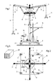
- the device according to the invention has a platform 1, which is supported here by four wheels 2, at least the wheels of one axle being steerable.
- a vertical support column 3 rises from this platform 1 and can be rotated about its vertical axis by means of a drive motor 4 and possibly a countershaft 5.
- Drive motors are also provided for driving the wheels 2 and for steering them, but here for the sake of clarity are not shown, these drive motors are expediently arranged within the box-like configuration of the platform 1.
- brackets 6 are provided here, which are arranged in a cross shape and each form an angle of 90 ° between them.
- a lifting rope 9 is guided over deflection rollers 7 and 8, which are provided on each boom 6, each lifting rope 9 being assigned its own cable winch 10 and its own drive motor 11. These components are expediently arranged on a bracket 12 of the support column 3.
- Each hoist rope 6 carries a gripper 13 which can be actuated by means of a handle 14.
- the individual drive motors are program controlled.
- a control panel 15 for this program control is provided on the platform 1.
- a work platform 6 is provided on this device, which is mounted here in a height-adjustable manner by means of two lifting spindles 17.
- This working platform 16 is dimensioned with respect to its length and width so that its outer corner points 18 and 19 lie within the envelope circle that the hanging strands of the lifting ropes 9 describe, i. that is, the radial distance between these corner points 18 and 19 is smaller than the radius of the envelope circle mentioned.
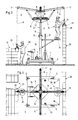
- 3 and 4 illustrate the operational use in a view and in a top view: parallel to and at a distance from the wall 20 to be erected, a row of pallets 21 is stored by brick.
- the device described above is located between the wall 20 to be erected and this row of pallets 21.
- a worker 24 stands on the work platform 16, a second worker on the pallet row 21.
- the drive motor 4 for the rotary movement of the support column 3 is switched on and program-controlled, as are the motors 11 for the lifting ropes 9.
- FIG. 3 shows now that moment in the workflow at which one - here left - hoist rope 9 is lowered so that the worker 22 can grasp a stored brick 23 by means of the retracted gripper 13, the second worker 24 on the work platform 16 releases the one retracted at that time Brick 25 from the gripper 13, which is deposited by this in its correct position on the row of bricks.
- the grippers 13 of the lifting ropes of those two brackets are located at right angles to the drawing plane at approximately half the working height H / 2, whereby - provided that the device rotates clockwise - the empty one lying in front of the drawing plane The gripper moves downwards, the gripper behind the drawing level with a set brick, however, goes up.
- the workers standing on the work platform 16 are supplied with the bricks directly via the periodically retracting grippers, in such a way that the retracted brick arrives tangentially on a circular arc at the location provided for it, so that the worker 24 only has to open the gripper when the brick has reached its intended position.
- the device moves slowly at right angles to the drawing plane while the wall is being built (Fig. 3).
- bricks are used and used for the construction of such masonry, as they are shown in Fig. 5, which therefore have grooves or tongues on the end faces and which have flat and precisely aligned boundary surfaces, the bearing surfaces being somewhat convex, as is the case is described and explained in the Austrian patent specification A 2368/89.
- Such bricks are glued, i.e. laid without a mortar bed. A worker, not shown here, applies the adhesive to the brick row laid.
- the hoisting ropes 9 raise and lower with their grippers 13 in a preselectable, periodic workflow and without manual intervention.
- the two workers shown here only have the task of gripping a new brick with the lowered gripper 13 (FIG. 3, left), or of releasing the brick 25 raised and retracted onto the brick row from the gripper.
- the height of the working platform 16 is advantageously adjusted by manual intervention, so that each worker can approach the working height adapted to his body size himself.
- the device moves to the point where the wall to be erected merges into a corner.
- the steerable wheels come into action and rotate the chassis about its vertical axis by 90 ° or that angle which corresponds to the corner to be bricked, so that the work platform 16 is again parallel to the masonry with its outer longitudinal edge.
- This working platform is dimensioned in terms of its width and length so that it lies entirely within the envelope circle that the suspended rope runs with the grippers run over during operation of the facility, so that the worker stands within the area run over by the picked up bricks.
- the arms 6 can protrude horizontally, or they can also have an inclination with respect to the horizontal. The height of this facility is adjusted to the normal and usual floor heights.
- the chassis has four wheels, it would be conceivable to mount the chassis on three wheels, for example, but there is no doubt that the stability of the device is improved by four wheels. It is expedient to mount the drive motors 11 for the cable winches 10 on an elevated console. There is sufficient space under these rigid arms, so that the platform 1 or its surface can be equipped with other components. Since the support column rotates constantly during the workflow, rotation-proof contact connections are to be provided for the power supply to the motors 11. Such belong to the prior art.
- baffle plate for laying the bricks 25 in the wall structure, which has the task of aligning the brick 25 supplied to the worker 24 by the hoist.
- This guide plate or this guide vane is designed to be pluggable and inserted into an already laid stone, the guide plate or the guide vane protruding somewhat obliquely from the escape of the wall and thus forming a start-up and alignment ramp for the brick running and retracting on the gripper 13.
Landscapes
- Engineering & Computer Science (AREA)
- Architecture (AREA)
- Mechanical Engineering (AREA)
- Civil Engineering (AREA)
- Structural Engineering (AREA)
- Conveying And Assembling Of Building Elements In Situ (AREA)
- Furnace Housings, Linings, Walls, And Ceilings (AREA)
- Waste-Gas Treatment And Other Accessory Devices For Furnaces (AREA)
- Jib Cranes (AREA)
Applications Claiming Priority (2)
| Application Number | Priority Date | Filing Date | Title |
|---|---|---|---|
| AT833/90 | 1990-04-09 | ||
| AT0083390A ATA83390A (de) | 1990-04-09 | 1990-04-09 | Einrichtung zur rationalisierung der verlegung von mauersteinen |
Publications (2)
| Publication Number | Publication Date |
|---|---|
| EP0451655A1 true EP0451655A1 (fr) | 1991-10-16 |
| EP0451655B1 EP0451655B1 (fr) | 1993-09-29 |
Family
ID=3500835
Family Applications (1)
| Application Number | Title | Priority Date | Filing Date |
|---|---|---|---|
| EP91105116A Expired - Lifetime EP0451655B1 (fr) | 1990-04-09 | 1991-03-30 | Dispositif pour la rationalisation de la pose de briques |
Country Status (3)
| Country | Link |
|---|---|
| EP (1) | EP0451655B1 (fr) |
| AT (2) | ATA83390A (fr) |
| DE (1) | DE59100413D1 (fr) |
Cited By (8)
| Publication number | Priority date | Publication date | Assignee | Title |
|---|---|---|---|---|
| DE9114808U1 (de) * | 1991-11-28 | 1992-02-13 | Schoch, Manfred, 7293 Pfalzgrafenweiler | Arbeitsgerät mit einer Arbeitsbühne und einem Kran |
| DE4300849A1 (de) * | 1993-01-15 | 1993-10-14 | Franz Weber | Hubarbeitsbühne zum Vermauern von Steinen |
| DE10256796A1 (de) * | 2002-12-05 | 2004-06-24 | Albert Böcker GmbH & Co KG | Mobilkran |
| CN103145048A (zh) * | 2013-04-02 | 2013-06-12 | 零永孝 | 水泥砖装载机 |
| FR2988711A1 (fr) * | 2012-03-30 | 2013-10-04 | Mathieu Paul Michel Laumond | Machine de manutention et de pose de blocs de maconnerie sur des murs |
| FR3033323A1 (fr) * | 2015-03-02 | 2016-09-09 | Xlbv | Plateforme et procede de modification de la position d'au moins une potence de levage d'une telle plateforme. |
| RU2606886C1 (ru) * | 2015-12-14 | 2017-01-10 | Павел Степанович Тигунцев | Автоматизированный способ возведения зданий из строительных блоков |
| CN111719871A (zh) * | 2020-07-10 | 2020-09-29 | 合肥浩凌机械设计制造有限公司 | 一种装配式钢结构房屋钢架安装方法 |
Citations (4)
| Publication number | Priority date | Publication date | Assignee | Title |
|---|---|---|---|---|
| US4122648A (en) * | 1977-06-09 | 1978-10-31 | Godwin Fred D | Apparatus for placing masonry modules |
| DE3445910A1 (de) * | 1984-12-15 | 1986-06-26 | Heinrich 7257 Ditzingen Stefan | Bauhilfsmaschine |
| DE3604130A1 (de) * | 1986-02-10 | 1987-08-13 | Adolf Metz | Mechanische maurerhilfe |
| DE3604224A1 (de) * | 1986-02-11 | 1987-08-13 | Lorenz Kesting | Vorrichtung zum mauern grossformatiger mauersteine |
-
1990
- 1990-04-09 AT AT0083390A patent/ATA83390A/de not_active IP Right Cessation
-
1991
- 1991-03-30 EP EP91105116A patent/EP0451655B1/fr not_active Expired - Lifetime
- 1991-03-30 DE DE91105116T patent/DE59100413D1/de not_active Expired - Fee Related
- 1991-03-30 AT AT91105116T patent/ATE95266T1/de not_active IP Right Cessation
Patent Citations (4)
| Publication number | Priority date | Publication date | Assignee | Title |
|---|---|---|---|---|
| US4122648A (en) * | 1977-06-09 | 1978-10-31 | Godwin Fred D | Apparatus for placing masonry modules |
| DE3445910A1 (de) * | 1984-12-15 | 1986-06-26 | Heinrich 7257 Ditzingen Stefan | Bauhilfsmaschine |
| DE3604130A1 (de) * | 1986-02-10 | 1987-08-13 | Adolf Metz | Mechanische maurerhilfe |
| DE3604224A1 (de) * | 1986-02-11 | 1987-08-13 | Lorenz Kesting | Vorrichtung zum mauern grossformatiger mauersteine |
Cited By (12)
| Publication number | Priority date | Publication date | Assignee | Title |
|---|---|---|---|---|
| DE9114808U1 (de) * | 1991-11-28 | 1992-02-13 | Schoch, Manfred, 7293 Pfalzgrafenweiler | Arbeitsgerät mit einer Arbeitsbühne und einem Kran |
| DE4239622A1 (en) * | 1991-11-28 | 1993-06-03 | Rolf Schoch | Crane and combined platform for handling building stone - three sectioned crane arm deployed from portable platform which used for storing and moving building stone |
| DE4300849A1 (de) * | 1993-01-15 | 1993-10-14 | Franz Weber | Hubarbeitsbühne zum Vermauern von Steinen |
| DE10256796A1 (de) * | 2002-12-05 | 2004-06-24 | Albert Böcker GmbH & Co KG | Mobilkran |
| DE10256796B4 (de) * | 2002-12-05 | 2006-09-28 | Albert Böcker GmbH & Co KG | Mobilkran |
| FR2988711A1 (fr) * | 2012-03-30 | 2013-10-04 | Mathieu Paul Michel Laumond | Machine de manutention et de pose de blocs de maconnerie sur des murs |
| CN103145048A (zh) * | 2013-04-02 | 2013-06-12 | 零永孝 | 水泥砖装载机 |
| CN103145048B (zh) * | 2013-04-02 | 2014-12-03 | 零永孝 | 水泥砖装载机 |
| FR3033323A1 (fr) * | 2015-03-02 | 2016-09-09 | Xlbv | Plateforme et procede de modification de la position d'au moins une potence de levage d'une telle plateforme. |
| WO2016139423A1 (fr) | 2015-03-02 | 2016-09-09 | Xlbv | Plateforme et procédé de modification de la position d'au moins une potence de levage d'une telle plateforme |
| RU2606886C1 (ru) * | 2015-12-14 | 2017-01-10 | Павел Степанович Тигунцев | Автоматизированный способ возведения зданий из строительных блоков |
| CN111719871A (zh) * | 2020-07-10 | 2020-09-29 | 合肥浩凌机械设计制造有限公司 | 一种装配式钢结构房屋钢架安装方法 |
Also Published As
| Publication number | Publication date |
|---|---|
| EP0451655B1 (fr) | 1993-09-29 |
| ATE95266T1 (de) | 1993-10-15 |
| DE59100413D1 (de) | 1993-11-04 |
| ATA83390A (de) | 1995-05-15 |
Similar Documents
| Publication | Publication Date | Title |
|---|---|---|
| EP3938597B1 (fr) | Machine de construction et/ou de manutention de matériau ainsi que procédé pour guider et déplacer une tête de travail | |
| DE69515299T2 (de) | Verfahren und vorrichtung für das installieren von leichtgewicht-paneelelementen | |
| DE2400313B2 (de) | Hilfseinrichtung fuer montage- und wartungsarbeiten an einem kuehlturm | |
| DE2441278B2 (de) | Abstützung für einen Drehkran | |
| EP0451655B1 (fr) | Dispositif pour la rationalisation de la pose de briques | |
| DE3136102C2 (de) | Kleinkran zum lagenweisen Vermauern von insbesondere großformatigen Mauersteinen | |
| DE2619334C2 (de) | "Als Halsdreher ausgebildeter Kletterkran für Bauzwecke mit wenigstens einer Betonverteilereinrichtung" | |
| EP2598819A1 (fr) | Plate-forme principale de travail et son utilisation | |
| EP0626339A1 (fr) | Pont roulant comportant une construction pour plateforme de travail, en particulier pour la maintenance d'avions | |
| DE3604224C2 (fr) | ||
| DE2363261C3 (de) | Einrichtung zur Steuerung der Bewegung der Ausleger eines ersten und mindestens eines zweiten Krans | |
| DE3607865A1 (de) | Einrichtung zum transportieren von containern oder stueckgut | |
| DE2313516A1 (de) | Vorrichtung zum aufnehmen und versetzen von lasten | |
| DE3418923A1 (de) | Anlage zum versetzen von mauersteinen | |
| DE3722244A1 (de) | Vorrichtung zur herstellung von waenden aus mauerwerk | |
| DE2406588A1 (de) | Bausteinmauermaschine | |
| DE4224631C2 (de) | Verfahren und Vorrichtung zum Befahren von Türmen, Kaminen, Schächten oder dergleichen mittels einer Arbeitsbühne | |
| DE3320010C1 (de) | Fassadenaufzug mit Zusatzausleger | |
| EP0659165B1 (fr) | Plate-forme de levage | |
| DE29521389U1 (de) | Turmkran mit Betonverteilereinrichtung | |
| DE2261658A1 (de) | Stapelkran | |
| DE3611716C2 (fr) | ||
| DE3733622A1 (de) | Umstapel- und foerder-einrichtung fuer werkstueck-paletten | |
| DE270344C (fr) | ||
| DE2660734C2 (de) | Als Halsdreher ausgebildeter Kletterkran für Bauzwecke mit wenigstens einer Betonverteilereinrichtung |
Legal Events
| Date | Code | Title | Description |
|---|---|---|---|
| PUAI | Public reference made under article 153(3) epc to a published international application that has entered the european phase |
Free format text: ORIGINAL CODE: 0009012 |
|
| AK | Designated contracting states |
Kind code of ref document: A1 Designated state(s): AT BE CH DE FR GB IT LI LU NL SE |
|
| 17P | Request for examination filed |
Effective date: 19911107 |
|
| 17Q | First examination report despatched |
Effective date: 19921111 |
|
| GRAA | (expected) grant |
Free format text: ORIGINAL CODE: 0009210 |
|
| AK | Designated contracting states |
Kind code of ref document: B1 Designated state(s): AT BE CH DE FR GB IT LI LU NL SE |
|
| PG25 | Lapsed in a contracting state [announced via postgrant information from national office to epo] |
Ref country code: IT Free format text: LAPSE BECAUSE OF FAILURE TO SUBMIT A TRANSLATION OF THE DESCRIPTION OR TO PAY THE FEE WITHIN THE PRE;WARNING: LAPSES OF ITALIAN PATENTS WITH EFFECTIVE DATE BEFORE 2007 MAY HAVE OCCURRED AT ANY TIME BEFORE 2007. THE CORRECT EFFECTIVE DATE MAY BE DIFFERENT FROM THE ONE RECORDED.SCRIBED TIME-LIMIT Effective date: 19930929 Ref country code: NL Effective date: 19930929 Ref country code: SE Effective date: 19930929 Ref country code: FR Effective date: 19930929 Ref country code: GB Effective date: 19930929 Ref country code: BE Effective date: 19930929 |
|
| REF | Corresponds to: |
Ref document number: 95266 Country of ref document: AT Date of ref document: 19931015 Kind code of ref document: T |
|
| REF | Corresponds to: |
Ref document number: 59100413 Country of ref document: DE Date of ref document: 19931104 |
|
| EN | Fr: translation not filed | ||
| NLV1 | Nl: lapsed or annulled due to failure to fulfill the requirements of art. 29p and 29m of the patents act | ||
| PG25 | Lapsed in a contracting state [announced via postgrant information from national office to epo] |
Ref country code: LU Free format text: LAPSE BECAUSE OF NON-PAYMENT OF DUE FEES Effective date: 19940331 |
|
| GBV | Gb: ep patent (uk) treated as always having been void in accordance with gb section 77(7)/1977 [no translation filed] |
Effective date: 19930929 |
|
| PLBE | No opposition filed within time limit |
Free format text: ORIGINAL CODE: 0009261 |
|
| STAA | Information on the status of an ep patent application or granted ep patent |
Free format text: STATUS: NO OPPOSITION FILED WITHIN TIME LIMIT |
|
| 26N | No opposition filed | ||
| REG | Reference to a national code |
Ref country code: CH Ref legal event code: NV Representative=s name: DR. CONRAD A. RIEDERER PATENTANWALT Ref country code: CH Ref legal event code: PUE Owner name: GUNTRAM MOOSBRUGGER TRANSFER- JOSEF FROEWIS |
|
| PGFP | Annual fee paid to national office [announced via postgrant information from national office to epo] |
Ref country code: AT Payment date: 20000204 Year of fee payment: 10 Ref country code: DE Payment date: 20000204 Year of fee payment: 10 |
|
| PGFP | Annual fee paid to national office [announced via postgrant information from national office to epo] |
Ref country code: CH Payment date: 20000228 Year of fee payment: 10 |
|
| PG25 | Lapsed in a contracting state [announced via postgrant information from national office to epo] |
Ref country code: AT Free format text: LAPSE BECAUSE OF NON-PAYMENT OF DUE FEES Effective date: 20010330 |
|
| PG25 | Lapsed in a contracting state [announced via postgrant information from national office to epo] |
Ref country code: CH Free format text: LAPSE BECAUSE OF NON-PAYMENT OF DUE FEES Effective date: 20010331 Ref country code: LI Free format text: LAPSE BECAUSE OF NON-PAYMENT OF DUE FEES Effective date: 20010331 |
|
| REG | Reference to a national code |
Ref country code: CH Ref legal event code: PL |
|
| PG25 | Lapsed in a contracting state [announced via postgrant information from national office to epo] |
Ref country code: DE Free format text: LAPSE BECAUSE OF NON-PAYMENT OF DUE FEES Effective date: 20020101 |