EP0451671A1 - Stütze für einen Spiess in einem elektrischen Ofen mit Mikrowellen und Heizelementen - Google Patents
Stütze für einen Spiess in einem elektrischen Ofen mit Mikrowellen und Heizelementen Download PDFInfo
- Publication number
- EP0451671A1 EP0451671A1 EP91105205A EP91105205A EP0451671A1 EP 0451671 A1 EP0451671 A1 EP 0451671A1 EP 91105205 A EP91105205 A EP 91105205A EP 91105205 A EP91105205 A EP 91105205A EP 0451671 A1 EP0451671 A1 EP 0451671A1
- Authority
- EP
- European Patent Office
- Prior art keywords
- foot
- axis
- opening
- support means
- support
- Prior art date
- Legal status (The legal status is an assumption and is not a legal conclusion. Google has not performed a legal analysis and makes no representation as to the accuracy of the status listed.)
- Granted
Links
- 238000010438 heat treatment Methods 0.000 title claims abstract description 5
- 230000002093 peripheral effect Effects 0.000 claims description 7
- 229910010293 ceramic material Inorganic materials 0.000 claims description 2
- 238000009434 installation Methods 0.000 claims description 2
- 241000272525 Anas platyrhynchos Species 0.000 description 2
- 238000010411 cooking Methods 0.000 description 2
- 239000000919 ceramic Substances 0.000 description 1
- 238000004519 manufacturing process Methods 0.000 description 1
- 239000000463 material Substances 0.000 description 1
- 239000002184 metal Substances 0.000 description 1
Images
Classifications
-
- F—MECHANICAL ENGINEERING; LIGHTING; HEATING; WEAPONS; BLASTING
- F24—HEATING; RANGES; VENTILATING
- F24C—DOMESTIC STOVES OR RANGES ; DETAILS OF DOMESTIC STOVES OR RANGES, OF GENERAL APPLICATION
- F24C15/00—Details
-
- F—MECHANICAL ENGINEERING; LIGHTING; HEATING; WEAPONS; BLASTING
- F24—HEATING; RANGES; VENTILATING
- F24C—DOMESTIC STOVES OR RANGES ; DETAILS OF DOMESTIC STOVES OR RANGES, OF GENERAL APPLICATION
- F24C15/00—Details
- F24C15/16—Shelves, racks or trays inside ovens; Supports therefor
- F24C15/164—Rotisserie spits inside ovens
-
- A—HUMAN NECESSITIES
- A47—FURNITURE; DOMESTIC ARTICLES OR APPLIANCES; COFFEE MILLS; SPICE MILLS; SUCTION CLEANERS IN GENERAL
- A47J—KITCHEN EQUIPMENT; COFFEE MILLS; SPICE MILLS; APPARATUS FOR MAKING BEVERAGES
- A47J37/00—Baking; Roasting; Grilling; Frying
- A47J37/04—Roasting apparatus with movably-mounted food supports or with movable heating implements; Spits
- A47J37/041—Roasting apparatus with movably-mounted food supports or with movable heating implements; Spits with food supports rotating about a horizontal axis
-
- F—MECHANICAL ENGINEERING; LIGHTING; HEATING; WEAPONS; BLASTING
- F24—HEATING; RANGES; VENTILATING
- F24C—DOMESTIC STOVES OR RANGES ; DETAILS OF DOMESTIC STOVES OR RANGES, OF GENERAL APPLICATION
- F24C15/00—Details
- F24C15/18—Arrangement of compartments additional to cooking compartments, e.g. for warming or for storing utensils or fuel containers; Arrangement of additional heating or cooking apparatus, e.g. grills
-
- Y—GENERAL TAGGING OF NEW TECHNOLOGICAL DEVELOPMENTS; GENERAL TAGGING OF CROSS-SECTIONAL TECHNOLOGIES SPANNING OVER SEVERAL SECTIONS OF THE IPC; TECHNICAL SUBJECTS COVERED BY FORMER USPC CROSS-REFERENCE ART COLLECTIONS [XRACs] AND DIGESTS
- Y10—TECHNICAL SUBJECTS COVERED BY FORMER USPC
- Y10S—TECHNICAL SUBJECTS COVERED BY FORMER USPC CROSS-REFERENCE ART COLLECTIONS [XRACs] AND DIGESTS
- Y10S99/00—Foods and beverages: apparatus
- Y10S99/14—Induction heating
Definitions
- the invention relates to a support means for a spindle intended to be mounted on a drip pan of a combined electric oven microwave and heating resistance, and comprising two opposite supports which are each insulated, on the one hand, from the spindle by an insulating ring which is crossed by the spindle, and, on the other hand, of said drip pan by an insulating base comprising a head which is intended to rest on a rim of the drip pan, and at least one foot with a lower surface to that of the underside of the head and intended to pass through a corresponding opening of the drip pan with a slight peripheral clearance.
- This type of support means has been described in French patent application No. 9000235 filed by the applicant on 10.1.90.
- This application relates to a type of oven comprising, in a cavity bounded by walls and a door, a drip pan equipped with such a support means receiving a spit and being able to occupy two positions, namely a cooking position for which the drip pan is at the interior of the cavity and the spindle is brought into the axis of a rotary drive mounted on one of the walls, that is to say a withdrawal position for which the drip pan is at least partially outside the cavity and the spindle is released from the coach.
- the disadvantage of the support means used is their tendency to loosen. Indeed, if you cook for example a large duck on a spit, the duck's legs can either rub against the walls or get stuck in a support, which causes the spit to tip out of its normal position. This results in a pivoting of the insulating base which leaves the openings and which, in certain cases, risks breaking, then by the fall of the support means and of the pin.
- the invention aims to remedy this drawback by avoiding the fall and breakage of the support means.
- each opening comprising a falling edge constituting a skirt
- the height and the horizontal section of the foot are dimensioned as a function of the horizontal section of the opening so that, during a tilting of the support means around 'a horizontal axis by pressing a peripheral part of the head on the edge of the drip pan, a region of the foot opposite said axis bears against the skirt, thus preventing the foot from coming out of the opening.
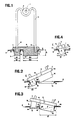
- FIG. 1 is a view in cross section of the spindle of a support means, according to the invention, mounted in the drip pan openings;
- Figure 2 shows in elevation the insulating base mounted in the openings of the drip pan and in a tilted position transversely to the left;
- Figure 3 is a view similar to Figure 2 illustrating a transverse tilt to the right;
- Figure 4 is an axial elevational view of the insulating base in an axially tilted position.
- the support means of a spindle 1 shown in Figure 1 is intended to be mounted on a drip pan 2 of a combined electric oven microwave and heating resistance (not shown).
- the universal pan 2 as described in patent application n ° 9000235 filed by the applicant on 10.01.90, comes to occupy a cooking position inside the oven cavity (not shown), for which the spit 1 is in the axis of a rotary drive (not shown) mounted on a wall of the cavity.
- the support means comprises two opposite metal supports 3 in the shape of a U which are each isolated, on the one hand, from the pin 1 by an insulating ring 4 made of ceramic which is crossed by the pin 1, and, on the other hand, of said universal pan 2 by an insulating base 5.
- Each support 3 is fixed to the base 5 by cementing the end 6 of its branches.
- Each insulating base 5 comprises a head 7 which is intended to rest on a flange 8 of the drip pan 2, and two feet 9, 10 of total horizontal section less than that of the lower face 11 of the head 7 and intended each to pass through a corresponding opening 12,13 made in the rim 8 of the universal pan 2 with a slight peripheral clearance.
- the insulating base 5 is preferably made in one piece from a ceramic material of the soapstone type which is transparent to microwaves.
- each opening 12,13 having a falling edge 14 constituting a skirt, the height h and the horizontal section s1 , s2 of each leg 9,10 are dimensioned as a function of the horizontal section a1 , a2 of the corresponding opening 12,13 so that, during a tilting of the means support around a horizontal axis 15,16,17 by pressing a peripheral part 18 of the head 7 on the rim 8 of the universal pan 2, a region 19-20-21 of the corresponding foot 9-10 opposite said axis 15-16-17 comes to bear against the skirt 14, thus preventing said foot 9,10 from coming out of its opening 12,13.
- Said axis 15, 16, 17 is materialized by the line of contact between the rim 8 of the drip pan and the peripheral part 18 of the head.
- the tilting can be caused for example by friction or hooking of the piece plugged on the walls of the cavity or on the supports 3.
- the tilting can be transverse to the axis of the spindle 1 ( Figure 2 and 3) or axial to pin 1 (figure 4).
- each leg 9-10 is such that the tilting radius r which is equal to the distance from the tilting axis 15-16-17 to the region 19 -20-21 of foot 9-10 furthest from axis 15-16-17 is greater than the distance d between said axis 15-16-17 and the upper edge 22 of opening 12-13 opposite to l '' axis 15-16-17.
- the tilting radius r depends on the height h and section s1 - s2 of the foot 9-10 and on the distance l between the axis 15-16-17 and the foot 9-10.
- the insulating base 5 of the first support 3 comprises two spaced apart feet 9, 10 of different sizes (FIGS. 1 to 4), while the insulating base of the second support (not shown) comprises two spaced feet of identical size, so as to avoid the 'interchangeability of the support means at the time of installation by the user.
- the feet 9,10 must each have a section s1 , s2 large enough to withstand the forces, in particular in the case of an axial tilting where the risks of seeing the feet 9,10 are greater.
- an oblong section is preferably chosen for at least one foot.
Landscapes
- Engineering & Computer Science (AREA)
- Chemical & Material Sciences (AREA)
- Combustion & Propulsion (AREA)
- Mechanical Engineering (AREA)
- General Engineering & Computer Science (AREA)
- Food Science & Technology (AREA)
- Cookers (AREA)
- Lubricants (AREA)
- Baking, Grill, Roasting (AREA)
- Electric Stoves And Ranges (AREA)
- Electric Ovens (AREA)
- Constitution Of High-Frequency Heating (AREA)
Applications Claiming Priority (2)
| Application Number | Priority Date | Filing Date | Title |
|---|---|---|---|
| FR9004540A FR2660737B3 (fr) | 1990-04-09 | 1990-04-09 | Moyen de support d'une broche dans un four electrique combine micro-ondes et resistance chauffante. |
| FR9004540 | 1990-04-09 |
Publications (2)
| Publication Number | Publication Date |
|---|---|
| EP0451671A1 true EP0451671A1 (de) | 1991-10-16 |
| EP0451671B1 EP0451671B1 (de) | 1994-02-02 |
Family
ID=9395580
Family Applications (1)
| Application Number | Title | Priority Date | Filing Date |
|---|---|---|---|
| EP91105205A Expired - Lifetime EP0451671B1 (de) | 1990-04-09 | 1991-04-02 | Stütze für einen Spiess in einem elektrischen Ofen mit Mikrowellen und Heizelementen |
Country Status (8)
| Country | Link |
|---|---|
| US (1) | US5162628A (de) |
| EP (1) | EP0451671B1 (de) |
| KR (1) | KR950001469B1 (de) |
| BR (1) | BR9101402A (de) |
| DE (1) | DE69101117T2 (de) |
| ES (1) | ES2050004T3 (de) |
| FR (1) | FR2660737B3 (de) |
| PT (1) | PT8699U (de) |
Families Citing this family (5)
| Publication number | Priority date | Publication date | Assignee | Title |
|---|---|---|---|---|
| US6539336B1 (en) | 1996-12-12 | 2003-03-25 | Phatrat Technologies, Inc. | Sport monitoring system for determining airtime, speed, power absorbed and other factors such as drop distance |
| US7780628B1 (en) * | 1999-01-11 | 2010-08-24 | Angiodynamics, Inc. | Apparatus and methods for treating congestive heart disease |
| KR101601278B1 (ko) * | 2009-11-03 | 2016-03-08 | 엘지전자 주식회사 | 이온수기 |
| EP2357414B1 (de) * | 2009-12-21 | 2018-06-20 | BSH Hausgeräte GmbH | Hausgerät zum Zubereiten von Lebensmitteln mit einer Lagerbuchse |
| US10251403B2 (en) * | 2010-10-06 | 2019-04-09 | Racquel Hartman | Baking pan for tilted cakes |
Citations (5)
| Publication number | Priority date | Publication date | Assignee | Title |
|---|---|---|---|---|
| GB927999A (en) * | 1961-09-25 | 1963-06-06 | Moffats Ltd | Dual purpose oven rack |
| DE1679001A1 (de) * | 1967-10-06 | 1971-03-04 | Neff Werke | Drehspiesslagerung und Antrieb in Brat-und Backoefen |
| DE2205562A1 (de) * | 1972-02-07 | 1973-09-13 | Jega Friedrichsthaler Eisen | Grilleinrichtung fuer brat- und backoefen |
| US4455467A (en) * | 1981-09-21 | 1984-06-19 | General Electric Company | Metal rack for microwave oven |
| DE8701917U1 (de) * | 1987-02-09 | 1987-10-01 | Licentia Patent-Verwaltungs-Gmbh, 6000 Frankfurt | Muffel für einen Back- und Bratofen |
Family Cites Families (4)
| Publication number | Priority date | Publication date | Assignee | Title |
|---|---|---|---|---|
| US4074102A (en) * | 1976-03-10 | 1978-02-14 | Donald Asen | Microwave oven rack |
| US4458585A (en) * | 1983-06-14 | 1984-07-10 | Weber-Stephen Products Co. | Rack for barbecue grill |
| US4709626A (en) * | 1985-09-13 | 1987-12-01 | Hamlyn Overseas Trading Company Pty Ltd | Foldable chicken holder |
| US4952764A (en) * | 1989-04-27 | 1990-08-28 | Harrington Lawrence S | Adjustable fin bacon rack for microwave oven |
-
1990
- 1990-04-09 FR FR9004540A patent/FR2660737B3/fr not_active Expired - Lifetime
-
1991
- 1991-04-02 EP EP91105205A patent/EP0451671B1/de not_active Expired - Lifetime
- 1991-04-02 DE DE69101117T patent/DE69101117T2/de not_active Expired - Fee Related
- 1991-04-02 ES ES91105205T patent/ES2050004T3/es not_active Expired - Lifetime
- 1991-04-08 BR BR919101402A patent/BR9101402A/pt not_active IP Right Cessation
- 1991-04-09 US US07/682,539 patent/US5162628A/en not_active Expired - Fee Related
- 1991-04-09 KR KR1019910005677A patent/KR950001469B1/ko not_active Expired - Fee Related
-
1993
- 1993-02-12 PT PT8699U patent/PT8699U/pt not_active IP Right Cessation
Patent Citations (5)
| Publication number | Priority date | Publication date | Assignee | Title |
|---|---|---|---|---|
| GB927999A (en) * | 1961-09-25 | 1963-06-06 | Moffats Ltd | Dual purpose oven rack |
| DE1679001A1 (de) * | 1967-10-06 | 1971-03-04 | Neff Werke | Drehspiesslagerung und Antrieb in Brat-und Backoefen |
| DE2205562A1 (de) * | 1972-02-07 | 1973-09-13 | Jega Friedrichsthaler Eisen | Grilleinrichtung fuer brat- und backoefen |
| US4455467A (en) * | 1981-09-21 | 1984-06-19 | General Electric Company | Metal rack for microwave oven |
| DE8701917U1 (de) * | 1987-02-09 | 1987-10-01 | Licentia Patent-Verwaltungs-Gmbh, 6000 Frankfurt | Muffel für einen Back- und Bratofen |
Also Published As
| Publication number | Publication date |
|---|---|
| KR950001469B1 (ko) | 1995-02-24 |
| KR910018737A (ko) | 1991-11-30 |
| FR2660737A3 (fr) | 1991-10-11 |
| DE69101117T2 (de) | 1994-06-01 |
| US5162628A (en) | 1992-11-10 |
| ES2050004T3 (es) | 1994-05-01 |
| EP0451671B1 (de) | 1994-02-02 |
| DE69101117D1 (de) | 1994-03-17 |
| PT8699U (pt) | 1995-12-29 |
| FR2660737B3 (fr) | 1992-04-24 |
| BR9101402A (pt) | 1991-11-26 |
| PT8699T (pt) | 1993-07-30 |
Similar Documents
| Publication | Publication Date | Title |
|---|---|---|
| EP2434933B1 (de) | Elektrhaushaltsgerät für speisenzubereitung mit eienr basis zur aufnahme eines arbeitsgefässes mit einer wärmeplatte | |
| CH264858A (fr) | Elément chauffant électrique. | |
| EP0438072B1 (de) | Elektrischer Ofen, kombiniert mit Mikrowellen und Heizelement | |
| EP0451671B1 (de) | Stütze für einen Spiess in einem elektrischen Ofen mit Mikrowellen und Heizelementen | |
| EP0792608B1 (de) | Scharnier für Elektrokochplatten und Kochgerät mit Scharnier | |
| EP2311355B1 (de) | Längliches Raclette-Gerät | |
| EP0810838B1 (de) | Kochgerät mit ringförmigem griff | |
| EP0845235B1 (de) | Toaster mit einem komplementären System zum Heben des Brotschlittens | |
| FR2882640A1 (fr) | Appareil electromenager de preparation culinaire de type blender comprenant un baton melangeur | |
| FR2768608A1 (fr) | Appareil electromenager de preparation culinaire, du genre robot menager multi-usages, comportant un ensemble de travail rotatif associe a un moyen d'appui | |
| FR2650373A1 (fr) | Couvercle pour plaque de cuisson integrable dans des dessus de meubles de cuisine | |
| FR2718337A1 (fr) | Dispositif pour assurer la cuisson d'aliments. | |
| EP0064453B1 (de) | Handleuchte für Glühlampen mit festangebrachtem Schutzkorb und demontierbarer Fassung | |
| EP0522960A1 (de) | Kochgerät mit elektrischer Widerstandsheizung | |
| FR3150695A1 (fr) | Appareil de chauffage d’aliments comprenant un couvercle équipé d’une partie d’écran thermique | |
| EP1060702B1 (de) | Verfahren zum Heben und Senken für einen Fritierkorb | |
| EP0726055B1 (de) | Elektrisches Kochgerät | |
| FR3150696A1 (fr) | Appareil de chauffage d’aliments comprenant un couvercle porté par une structure de support | |
| FR3150698A1 (fr) | Bol pour appareil de chauffage d’aliments, et appareil de chauffage d’aliments comprenant un tel bol | |
| FR3150694A1 (fr) | Appareil de chauffage d’aliments comprenant un bol pourvu d’un volume interne réduit | |
| FR2555143A1 (fr) | Emballage perdu pour cuisson de produits alimentaires | |
| FR3079122A1 (fr) | Crepiere multiplaque | |
| CH594395A5 (en) | Cooking spit with hollow rod attached to handle | |
| CH331164A (fr) | Gril électrique amovible adaptable à un récipient de cuisson | |
| EP0033287A1 (de) | Sicherheitsfassung für eine röhrenförmige Lampe mit axialen Endkappen |
Legal Events
| Date | Code | Title | Description |
|---|---|---|---|
| PUAI | Public reference made under article 153(3) epc to a published international application that has entered the european phase |
Free format text: ORIGINAL CODE: 0009012 |
|
| 17P | Request for examination filed |
Effective date: 19910819 |
|
| AK | Designated contracting states |
Kind code of ref document: A1 Designated state(s): DE ES GB IT NL SE |
|
| 17Q | First examination report despatched |
Effective date: 19921204 |
|
| GRAA | (expected) grant |
Free format text: ORIGINAL CODE: 0009210 |
|
| AK | Designated contracting states |
Kind code of ref document: B1 Designated state(s): DE ES GB IT NL SE |
|
| REF | Corresponds to: |
Ref document number: 69101117 Country of ref document: DE Date of ref document: 19940317 |
|
| ITF | It: translation for a ep patent filed | ||
| GBT | Gb: translation of ep patent filed (gb section 77(6)(a)/1977) |
Effective date: 19940223 |
|
| REG | Reference to a national code |
Ref country code: ES Ref legal event code: FG2A Ref document number: 2050004 Country of ref document: ES Kind code of ref document: T3 |
|
| PLBE | No opposition filed within time limit |
Free format text: ORIGINAL CODE: 0009261 |
|
| STAA | Information on the status of an ep patent application or granted ep patent |
Free format text: STATUS: NO OPPOSITION FILED WITHIN TIME LIMIT |
|
| 26N | No opposition filed | ||
| EAL | Se: european patent in force in sweden |
Ref document number: 91105205.8 |
|
| PGFP | Annual fee paid to national office [announced via postgrant information from national office to epo] |
Ref country code: SE Payment date: 20010306 Year of fee payment: 11 |
|
| PGFP | Annual fee paid to national office [announced via postgrant information from national office to epo] |
Ref country code: GB Payment date: 20010328 Year of fee payment: 11 |
|
| PGFP | Annual fee paid to national office [announced via postgrant information from national office to epo] |
Ref country code: ES Payment date: 20010416 Year of fee payment: 11 |
|
| PGFP | Annual fee paid to national office [announced via postgrant information from national office to epo] |
Ref country code: NL Payment date: 20010430 Year of fee payment: 11 Ref country code: DE Payment date: 20010430 Year of fee payment: 11 |
|
| REG | Reference to a national code |
Ref country code: GB Ref legal event code: IF02 |
|
| PG25 | Lapsed in a contracting state [announced via postgrant information from national office to epo] |
Ref country code: GB Free format text: LAPSE BECAUSE OF NON-PAYMENT OF DUE FEES Effective date: 20020402 |
|
| PG25 | Lapsed in a contracting state [announced via postgrant information from national office to epo] |
Ref country code: SE Free format text: LAPSE BECAUSE OF NON-PAYMENT OF DUE FEES Effective date: 20020403 Ref country code: ES Free format text: LAPSE BECAUSE OF NON-PAYMENT OF DUE FEES Effective date: 20020403 |
|
| PG25 | Lapsed in a contracting state [announced via postgrant information from national office to epo] |
Ref country code: NL Free format text: LAPSE BECAUSE OF NON-PAYMENT OF DUE FEES Effective date: 20021101 Ref country code: DE Free format text: LAPSE BECAUSE OF NON-PAYMENT OF DUE FEES Effective date: 20021101 |
|
| EUG | Se: european patent has lapsed |
Ref document number: 91105205.8 |
|
| GBPC | Gb: european patent ceased through non-payment of renewal fee |
Effective date: 20020402 |
|
| NLV4 | Nl: lapsed or anulled due to non-payment of the annual fee |
Effective date: 20021101 |
|
| REG | Reference to a national code |
Ref country code: ES Ref legal event code: FD2A Effective date: 20030514 |
|
| PG25 | Lapsed in a contracting state [announced via postgrant information from national office to epo] |
Ref country code: IT Free format text: LAPSE BECAUSE OF NON-PAYMENT OF DUE FEES;WARNING: LAPSES OF ITALIAN PATENTS WITH EFFECTIVE DATE BEFORE 2007 MAY HAVE OCCURRED AT ANY TIME BEFORE 2007. THE CORRECT EFFECTIVE DATE MAY BE DIFFERENT FROM THE ONE RECORDED. Effective date: 20050402 |