EP0451684A1 - Zahnradpumpe mit verbessertem Betrieb bei Tieftemperaturen - Google Patents
Zahnradpumpe mit verbessertem Betrieb bei Tieftemperaturen Download PDFInfo
- Publication number
- EP0451684A1 EP0451684A1 EP91105274A EP91105274A EP0451684A1 EP 0451684 A1 EP0451684 A1 EP 0451684A1 EP 91105274 A EP91105274 A EP 91105274A EP 91105274 A EP91105274 A EP 91105274A EP 0451684 A1 EP0451684 A1 EP 0451684A1
- Authority
- EP
- European Patent Office
- Prior art keywords
- pair
- members
- bushing
- gear
- housing
- Prior art date
- Legal status (The legal status is an assumption and is not a legal conclusion. Google has not performed a legal analysis and makes no representation as to the accuracy of the status listed.)
- Withdrawn
Links
- 238000007789 sealing Methods 0.000 claims abstract description 18
- 238000005086 pumping Methods 0.000 claims abstract 3
- 230000000295 complement effect Effects 0.000 claims abstract 2
- 239000007788 liquid Substances 0.000 claims description 23
- 239000012530 fluid Substances 0.000 abstract description 12
- 230000008602 contraction Effects 0.000 description 3
- OKTJSMMVPCPJKN-UHFFFAOYSA-N Carbon Chemical compound [C] OKTJSMMVPCPJKN-UHFFFAOYSA-N 0.000 description 2
- 238000010276 construction Methods 0.000 description 2
- 230000007812 deficiency Effects 0.000 description 2
- 229910052751 metal Inorganic materials 0.000 description 2
- 239000002184 metal Substances 0.000 description 2
- 229910000838 Al alloy Inorganic materials 0.000 description 1
- 229910001369 Brass Inorganic materials 0.000 description 1
- 239000010951 brass Substances 0.000 description 1
- 229910052799 carbon Inorganic materials 0.000 description 1
- 239000000110 cooling liquid Substances 0.000 description 1
- 229910002804 graphite Inorganic materials 0.000 description 1
- 239000010439 graphite Substances 0.000 description 1
- 238000011068 loading method Methods 0.000 description 1
- 230000001050 lubricating effect Effects 0.000 description 1
- 238000004519 manufacturing process Methods 0.000 description 1
- 239000000463 material Substances 0.000 description 1
- 238000000034 method Methods 0.000 description 1
- 230000036316 preload Effects 0.000 description 1
- 238000000926 separation method Methods 0.000 description 1
- 238000002791 soaking Methods 0.000 description 1
Images

Classifications
-
- F—MECHANICAL ENGINEERING; LIGHTING; HEATING; WEAPONS; BLASTING
- F04—POSITIVE - DISPLACEMENT MACHINES FOR LIQUIDS; PUMPS FOR LIQUIDS OR ELASTIC FLUIDS
- F04C—ROTARY-PISTON, OR OSCILLATING-PISTON, POSITIVE-DISPLACEMENT MACHINES FOR LIQUIDS; ROTARY-PISTON, OR OSCILLATING-PISTON, POSITIVE-DISPLACEMENT PUMPS
- F04C2/00—Rotary-piston machines or pumps
- F04C2/08—Rotary-piston machines or pumps of intermeshing-engagement type, i.e. with engagement of co-operating members similar to that of toothed gearing
- F04C2/082—Details specially related to intermeshing engagement type machines or pumps
- F04C2/088—Elements in the toothed wheels or the carter for relieving the pressure of fluid imprisoned in the zones of engagement
-
- F—MECHANICAL ENGINEERING; LIGHTING; HEATING; WEAPONS; BLASTING
- F04—POSITIVE - DISPLACEMENT MACHINES FOR LIQUIDS; PUMPS FOR LIQUIDS OR ELASTIC FLUIDS
- F04C—ROTARY-PISTON, OR OSCILLATING-PISTON, POSITIVE-DISPLACEMENT MACHINES FOR LIQUIDS; ROTARY-PISTON, OR OSCILLATING-PISTON, POSITIVE-DISPLACEMENT PUMPS
- F04C15/00—Component parts, details or accessories of machines, pumps or pumping installations, not provided for in groups F04C2/00 - F04C14/00
- F04C15/0003—Sealing arrangements in rotary-piston machines or pumps
- F04C15/0023—Axial sealings for working fluid
- F04C15/0026—Elements specially adapted for sealing of the lateral faces of intermeshing-engagement type machines or pumps, e.g. gear machines or pumps
Definitions
- the present invention is in the field of gear pumps. More particularly the present invention relates to a gear pump wherein a pair of meshed straight-cut spur gears are received within a housing having an inlet port and an outlet port leading to and from a cavity wherein the meshed gears are received.
- One of the meshed gears is driven by an output shaft extending externally of the housing, while the other gear is journaled in the housing as an idler and rotates because of its meshing engagement with the externally driven gear.
- the meshed gears rotate in opposite directions successive trapped volumes of fluid are carried by each gear from the inlet passage to the outlet passage.
- the mesh of the gears prevents fluid from being conveyed in the opposite direction.
- Such meshed gear pumps are old and very well known.
- conventional gear pumps are known wherein a housing portion of the pump is adjusted transversely relative to the gears in order to control radial clearance between the housing portion and the tips of the gear teeth.
- Such gear pumps are set forth in U.S. Patent No. 246,724, issued 6 September 1881 to A. S. Clark; and in U.S. Patent No. 3,433,168, issued 13 January 1967 to O. H. Baker; as well as in U.S. Patent No. 4,645,439, issued 24 February 1987 to D. R. Way.
- Also known are conventional gear pumps wherein a portion only of the housing is adjusted transversely of the gear pair in order to control the radial gap between the tips of the gear teeth and the housing portion.
- a gear pump may be provided with a housing secured axially by a pair of tie bolts or tie rod members extending parallel to the shafts of the meshed gears and exceedingly close to the mesh of these gears. These tie bolts preload the housing to resist axial separating forces generated by fluid pressures within the pump. In this way it is hoped to avoid the axial bowing apart of the housing portions of the pump resulting from fluid pressures within the pump. Such separation of the housing portions provides leakage past the meshed gears axially thereof.
- gear pumps are believed to suffer from a deficiency only apparent when such gear pumps are subjected to operation at exceedingly low temperatures.
- Such operation of gear pumps at exceedingly low temperatures occurs in the aerospace art as well as in other arts.
- conventional gear pumps when they are exposed to this type of dormant cold soak utilization experienced an exceedingly high drag torque when they are first started. This drag torque continues for a considerable period of time until the pumps approach their normal operating temperature, and in extreme cases this drag torque, which may be a virtual lock-up of the pump, may entirely prevent the starting or operation of the associated equipment upon which the gear pump is used.
- the present invention has as its object the provision of a gear pump particularly offering improved operation at low temperatures, and especially after an extended cold soak at such low temperatures as low as -54°C.
- the present invention provides a gear pump wherein a pair of meshed pinions are received within a housing cavity.
- the meshed pinions are journaled within the housing by a pair of bearing members which are relatively moveable both in an axial and in a radial sense within the housing.
- One of the meshed gear members includes a shaft extending externally of the housing through a bore thereof to receive a driving torque input.
- high pressure fluid originating with a trapped meshed volume between the pair of meshed gears is directed axially along the shaft portions which journal the gear members within the bushings and to a pair of pressure balance chambers at opposite ends of the pump.
- the pair of bushings are dimensioned to cooperatively control radial leakage paths between the outer gear tips of the gears and the housing itself.
- dimensions within the pump may be selected such that thermal contractions resulting from cold soak do not cause any of the relatively rotating and sliding components of the gear pump to seize against one another.
- the inventive pump avoids the undesirable characteristic of exceedingly high operating torques being generated when start up of the pump is desired after a cold-soak.
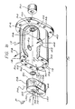
- the single drawing Figure depicts an exploded perspective view of the present inventive pump and its component parts, with a portion of the housing being broken away to better illustrate internal features.
- a gear pump 10 includes a housing 12 defining a cylindrical recess 14 therein.
- the recess 14 is generally oval and includes a pair of spaced apart surface portions 16, 18 which are right circular semi-cylindrical.
- the surface portions 16, 18 are joined by side wall surface portions 20, 22 which are planar and tangent with the portions 16, 18.
- An end wall 24 closes one end of recess 14, while the recess opens on a surface 26 at its other end.
- the housing defines an axially extending stepped bore 28 on one of the cylindrical axes of the surfaces 16, 18, opening through the end wall 24 within a boss (not visible in the drawing Figure).
- a conventional shaft sealing member 30 is received in the boss in juxtaposition with a smaller diameter portion 32 of the bore 28, which latter bore portion opens to the recess 14. Spaced radially outwardly of the bore portion 32, the end wall 24 defines an annular groove 34 into which is received a resilient O-ring type sealing member 36.
- the housing 12 includes a flange part 38 by which the pump 10 may be mounted to a driving device (not shown), for example, to a gear box, by a plurality of fasteners (also not shown) passing through bores 40 and engaging the gear box, or other drive device.
- An inlet port 42 is defined by the housing 12 and opens on the side wall surface portion 20 about midway between end wall 24 and the opening of recess 14 on surface 26. Via the inlet port 42, the pump 10 may receive an inlet flow of liquid, as is depicted by arrow 44.
- the housing 12 defines an outlet port 46 opening from recess 14 on the surface 22, and from which the pump 10 may discharge an outlet flow of pressurized liquid, as depicted by arrow 48.
- the housing 12 defines a plurality of threaded bores 50, by which a closure member 52 may be secured to the housing 12 by a plurality threaded fasteners 54.
- the closure member 52 defines a planar surface 56 sealingly engaging the surface 26 and spanning the recess 14 to close the latter at its opening on the housing 12.
- bushing and sealing members 58, 60 Received into the recess 14 is a pair of bushing and sealing members 58, 60, which with the exception of two features which will be pointed out below, are substantially mirror image duplicates of one another.
- the bushing members 58, 60 are complements to the geometric shape of the recess 14, and are closely fitted therein with sufficient clearance space to always allow relative movement between each bushing and the housing 12.
- the housing 12 may be made of metal, for example, an aluminum alloy.
- the bushings 58, 60 may be made of a metal, for example, of brass, or of carbon graphite.
- the clearance therebetween is chosen to be just sufficient to insure that the housing does not contract upon the bushings at very low temperatures, for example, temperatures as low as -54°C.
- the bushing 58, 60 are always movable axially and in a radial or lateral sense with respect to the cylindrical axes of the surfaces 16, 18 in recess 14.
- Each of the bushing members 58, 60 defines a pair of axially extending through bores 62, 64, and 66, 68, respectively, which each are disposed at its centerline on the cylindrical axes of the surfaces 16, 18.
- Each bushing 58, 60 on its end face confronting the other bushing defines a pair of radially and circumferentially extending recesses 70, 72, only the recesses of bushing 58 being visible in the drawing Figure.
- the recesses 70, 72 extend radially from near respective ones of the bores 62-68 toward, but short of each other, and are disposed toward the outlet port 46 with respect to a diametrical line 74 between the center of bores 62-64, and 66-68.
- Each bushing 58, 60 also defines an axially extending groove 76, 78, respectively, extending axially from end to end thereof, and only the opening on the end surfaces thereof being visible in the drawing Figure.
- the former defines a passage 80 extending generally axially through the bushing member.
- the passage 80 opens on one axial face of the bushing 58 adjacent the bore 62 radially inwardly of the sealing cooperation of member 36 with the bushing.
- Passage 80 is angulated and opens on the opposite axial face of the bushing 58 generally centrally thereof and toward the inlet port 42 with respect to line 74.
- the bushing 60 at its axial face disposed toward cover member 52 defines a pair of shallow counter bores 82, 84, surrounding the openings of the bores 66, 68 respectively.
- each of the counter-bores 82, 84 is a respective one of a pair of annular wave spring members 86, 88.
- the wave spring members 86, 88 engage the cover member 52 and bushing 60 to urge the latter and the entire contents of recess 14 toward end wall 24.
- the spur gear members 90, 92 each include a plurality of gear teeth 94, defining inter-tooth spaces 96 therebetween.
- the outer diameter of the spur gear members 90, 92, as determined at addendum circle tip surfaces 98 of the teeth 94 is substantially the same as the cylindrical diameter of the surfaces 16, 18 of housing 12.
- Each of the gear members 90, 92 includes a pair of axially extending shaft portions, 100, 102, and 104, 106, respectively.
- the shaft portions 100-106 are rotatably journaled in the bores 62-68 so that the bushings 58, 60 alone journal the gears 90, 92.
- Gear member 90 includes a drive shaft part 108 extending axially from and integral with the shaft portion 102.
- the drive shaft part 108 extends through bore 28 and sealing member 30 to project externally of the housing 12.
- Drive shaft part 108 includes a spline-defining termination section 110 whereat driving torque may be supplied to the pump 10, as depicted by arrow 112.
- Gear member 92 on the other hand, defines an axially extending central through bore 114 opening at opposite ends on the ends of the shaft portions 104, 106.
- the pair of bushings 58, 60 sandwich the pair of gear members 90, 92 therebetween and journal the shaft portions 100-106.
- the assembly of bushings 58, 60, and gear members 90, 92 is received into recess 14 with sealing member 36 in groove 34 sealingly engaging bushing 58.
- the wave spring members 86, 88 are received into counter bores 82, 84, and the closure member 52 closes the recess 14, and engages these wave spring members. Consequently, the bushing 60 is urged axially into sliding engagement with the axial faces of gear members 90, 94, and the latter are urged axially into sliding engagement at their axial faces with the bushing 60. Finally, bushing 60 is urged into engagement with end wall 24 and sealingly engages sealing member 36.
- each bushing member as well as the semi-cylindrical surfaces (all confronting surfaces 16, 18, and 22 of housing 12) are exposed to fluid pressure at the outlet port 46.
- This external surface exposure of the bushing members 58, 60 in addition to the pressure differential effective across the pair of gear members 90, 92, urges the bushing members 58, 60 into sealing engagement with the planar surface 20 of the housing 12, depicted by arrows 'P', and as is indicated by shaded areas 130.
- the assembly of bushings 58, 60 and gear members 90, 92 is floatingly received in the cavity 14, both with respect to axial relative movements to control leakage flows, and with respect to movements radially (or laterally) of the cylindrical axes of surfaces 16, 18 for the same purpose.
- the seal member 30 is selected to allow necessary axial and radial relative movement of shaft 108 while still preserving sealing relation therewith.
- the present inventive pump Because of the floating pressure-balanced, self sealing interrelationship of the component parts of the pump 10, sufficient clearance between the bushings 58, 60 and housing 12 may be provided to prevent cold-soak binding of the pump.
- the present inventive pump displays an almost negligible driving torque increase in this use. While conventional gear pumps appear to suffer from internal mechanical contacts and surface loadings resulting from required close running clearances and differential thermal contractions, the present pump allows use of sufficient large running clearances to avoid cold-soak increase of driving torque.
- the present inventive pump not only does not suffer any volume throughput penalty from use of the necessary running clearances outlined above, it enjoys a throughput advantage because about three-fourths of the intermesh trapped liquid volume flows to the outlet port.
Landscapes
- Engineering & Computer Science (AREA)
- Mechanical Engineering (AREA)
- General Engineering & Computer Science (AREA)
- Rotary Pumps (AREA)
Applications Claiming Priority (2)
| Application Number | Priority Date | Filing Date | Title |
|---|---|---|---|
| US07/509,006 US5076770A (en) | 1990-04-13 | 1990-04-13 | Gear pump having improved low temperature operation |
| US509006 | 1990-04-13 |
Publications (1)
| Publication Number | Publication Date |
|---|---|
| EP0451684A1 true EP0451684A1 (de) | 1991-10-16 |
Family
ID=24024939
Family Applications (1)
| Application Number | Title | Priority Date | Filing Date |
|---|---|---|---|
| EP91105274A Withdrawn EP0451684A1 (de) | 1990-04-13 | 1991-04-03 | Zahnradpumpe mit verbessertem Betrieb bei Tieftemperaturen |
Country Status (2)
| Country | Link |
|---|---|
| US (1) | US5076770A (de) |
| EP (1) | EP0451684A1 (de) |
Cited By (2)
| Publication number | Priority date | Publication date | Assignee | Title |
|---|---|---|---|---|
| US6494177B2 (en) | 2000-03-16 | 2002-12-17 | Harley-Davidson Motor Company Group, Inc. | Oil-pump drive for an internal-combustion engine |
| WO2011056314A1 (en) * | 2009-10-26 | 2011-05-12 | Stork Townsend Inc. | Meat emulsion pump |
Families Citing this family (11)
| Publication number | Priority date | Publication date | Assignee | Title |
|---|---|---|---|---|
| US5252047A (en) * | 1992-09-16 | 1993-10-12 | Allied-Signal, Inc. | Gear pump with controlled clamping force |
| DE69315227T2 (de) * | 1992-09-16 | 1998-03-19 | Allied Signal Inc | Zahnradpumpe mit regelbarer klemmkraft |
| US5702234A (en) * | 1995-12-01 | 1997-12-30 | Micropump, Inc. | Fluid pump with bearing set having lubrication path |
| DE19614894C2 (de) * | 1996-04-16 | 1997-12-11 | Hartmut Hasse | Extrusionskopf mit Mischeinrichtung und einstellbarem Schereffekt |
| CA2309458A1 (en) * | 1998-09-28 | 2000-04-06 | Dana Corporation | Lubrication system for hydraulic pumps |
| US6659728B2 (en) * | 2001-11-09 | 2003-12-09 | Viking Pump, Inc. | Liquid dispensing pump system |
| US9127674B2 (en) * | 2010-06-22 | 2015-09-08 | Gm Global Technology Operations, Llc | High efficiency fixed displacement vane pump including a compression spring |
| CZ201597A3 (cs) * | 2015-02-13 | 2016-02-24 | Jihostroj A.S. | Zubové čerpadlo s pohonem |
| ITUB201655126U1 (it) * | 2016-03-02 | 2017-09-02 | Fluid O Tech Srl | Assieme di contenimento elastico per una pompa. |
| US10962059B2 (en) * | 2019-06-17 | 2021-03-30 | Hamilton Sundstrand Corporation | Bearing with an eccentric seal groove |
| GB2629410B (en) * | 2023-04-27 | 2026-03-18 | Bamford Excavators Ltd | A hydraulic pump arrangement |
Citations (5)
| Publication number | Priority date | Publication date | Assignee | Title |
|---|---|---|---|---|
| GB739357A (en) * | 1954-01-28 | 1955-10-26 | Dowty Hydraulic Units Ltd | Improvements relating to gear pumps |
| FR1210914A (fr) * | 1957-09-11 | 1960-03-11 | Pompe à pignons montés sur des coussinets coulissants | |
| GB1097392A (en) * | 1963-12-11 | 1968-01-03 | Dowty Technical Dev Ltd | Gear pumps |
| US3833317A (en) * | 1971-03-04 | 1974-09-03 | R Rumsey | Rotary gear motor/pump having hydrostatic bearing means |
| FR2496184A1 (fr) * | 1980-12-15 | 1982-06-18 | Karl Marx Stadt Ind Werke | Machine hydrostatique a engrenages |
Family Cites Families (13)
| Publication number | Priority date | Publication date | Assignee | Title |
|---|---|---|---|---|
| US246724A (en) * | 1881-09-06 | Rotary pump | ||
| US1972271A (en) * | 1928-05-12 | 1934-09-04 | Mcintyre Frederic | Metering pump for cellulose compounds |
| US2728301A (en) * | 1952-06-17 | 1955-12-27 | Lindberg Trust | Gear pump |
| US2855854A (en) * | 1954-02-19 | 1958-10-14 | Thompson Prod Inc | Pump with pressure loaded shoe |
| DE1134590B (de) * | 1957-11-09 | 1962-08-09 | Bosch Gmbh Robert | Zahnradpumpe |
| US2986097A (en) * | 1959-01-07 | 1961-05-30 | Sundstrand Corp | Gear pump or motor device |
| US3306225A (en) * | 1964-07-08 | 1967-02-28 | Sylvester W Smith | Self-lubricating pump |
| US3433168A (en) * | 1967-01-13 | 1969-03-18 | Meyer Products Inc | Gear pump with takeup for wear |
| US3371615A (en) * | 1967-01-16 | 1968-03-05 | Borg Warner | Pressure loaded pump |
| US3560121A (en) * | 1969-02-28 | 1971-02-02 | Chandler Evans Inc | Gear pump with movable element having contiguous cyclic unloading suppression means |
| US3690793A (en) * | 1971-01-27 | 1972-09-12 | Sundstrand Corp | Gear pump with lubricating means |
| US3748063A (en) * | 1971-04-09 | 1973-07-24 | Cessna Aircraft Co | Pressure loaded gear pump |
| US4645439A (en) * | 1985-11-25 | 1987-02-24 | The Garrett Corporation | Adjustable gear pump |
-
1990
- 1990-04-13 US US07/509,006 patent/US5076770A/en not_active Expired - Lifetime
-
1991
- 1991-04-03 EP EP91105274A patent/EP0451684A1/de not_active Withdrawn
Patent Citations (5)
| Publication number | Priority date | Publication date | Assignee | Title |
|---|---|---|---|---|
| GB739357A (en) * | 1954-01-28 | 1955-10-26 | Dowty Hydraulic Units Ltd | Improvements relating to gear pumps |
| FR1210914A (fr) * | 1957-09-11 | 1960-03-11 | Pompe à pignons montés sur des coussinets coulissants | |
| GB1097392A (en) * | 1963-12-11 | 1968-01-03 | Dowty Technical Dev Ltd | Gear pumps |
| US3833317A (en) * | 1971-03-04 | 1974-09-03 | R Rumsey | Rotary gear motor/pump having hydrostatic bearing means |
| FR2496184A1 (fr) * | 1980-12-15 | 1982-06-18 | Karl Marx Stadt Ind Werke | Machine hydrostatique a engrenages |
Cited By (7)
| Publication number | Priority date | Publication date | Assignee | Title |
|---|---|---|---|---|
| US6494177B2 (en) | 2000-03-16 | 2002-12-17 | Harley-Davidson Motor Company Group, Inc. | Oil-pump drive for an internal-combustion engine |
| DE10012892B4 (de) * | 2000-03-16 | 2005-06-16 | Dr.Ing.H.C. F. Porsche Ag | Ölpumpenantrieb für eine Brennkraftmaschine |
| WO2011056314A1 (en) * | 2009-10-26 | 2011-05-12 | Stork Townsend Inc. | Meat emulsion pump |
| US8342916B2 (en) | 2009-10-26 | 2013-01-01 | Stork Townsend Inc. | Meat processing assembly |
| US8540554B2 (en) | 2009-10-26 | 2013-09-24 | Stork Townsend Inc. | Meat processing assembly |
| US9084430B2 (en) | 2009-10-26 | 2015-07-21 | Stork Townsend Inc. | Meat processing assembly |
| US9089148B2 (en) | 2009-10-26 | 2015-07-28 | Stork Townsend Inc. | Meat processing assembly |
Also Published As
| Publication number | Publication date |
|---|---|
| US5076770A (en) | 1991-12-31 |
Similar Documents
| Publication | Publication Date | Title |
|---|---|---|
| EP0451684A1 (de) | Zahnradpumpe mit verbessertem Betrieb bei Tieftemperaturen | |
| US6648611B2 (en) | Gerotor pump having an eccentric ring housing with an integral pressure chamber | |
| CA1046343A (en) | Gear pump | |
| US4940394A (en) | Adjustable wearplates rotary pump | |
| US5417556A (en) | Bearing for gear pump | |
| US2956512A (en) | Hydraulic pump or motor | |
| US2998783A (en) | Pressure-balanced gear pump | |
| US6206666B1 (en) | High efficiency gear pump | |
| US3482524A (en) | Pump or motor | |
| US3083645A (en) | Gear pump or the like | |
| EP0046293B1 (de) | Druckfluidum-Drehkolbenanlage mit Ventilsitzeinrichtung | |
| US2660958A (en) | Pressure loaded gear pump | |
| US4035113A (en) | Gerotor device with lubricant system | |
| US3433168A (en) | Gear pump with takeup for wear | |
| US4245969A (en) | Pump | |
| US2654325A (en) | Gear type pump with pressure loaded bushing and wear insert element | |
| US2808785A (en) | Rotary pumps or compressors | |
| US5252047A (en) | Gear pump with controlled clamping force | |
| US3429270A (en) | Gear pump movable elements having a plurality of sealing forces | |
| US3023706A (en) | Gear pump and relief valve | |
| US3153371A (en) | Delayed pressure loading for gear motors | |
| JP3102522B2 (ja) | ギヤポンプ | |
| EP0701661B1 (de) | Zahnradpumpe mit regelbarer klemmkraft | |
| US2734258A (en) | Method of assembling pressure loaded | |
| US4116588A (en) | Fluid pump |
Legal Events
| Date | Code | Title | Description |
|---|---|---|---|
| PUAI | Public reference made under article 153(3) epc to a published international application that has entered the european phase |
Free format text: ORIGINAL CODE: 0009012 |
|
| AK | Designated contracting states |
Kind code of ref document: A1 Designated state(s): DE FR GB IT SE |
|
| STAA | Information on the status of an ep patent application or granted ep patent |
Free format text: STATUS: THE APPLICATION IS DEEMED TO BE WITHDRAWN |
|
| 18D | Application deemed to be withdrawn |
Effective date: 19920417 |