EP0451690A2 - Procédé et dispositif de forage et/ou d'équipement des plaques de guidage d'un adaptateur d'essai - Google Patents
Procédé et dispositif de forage et/ou d'équipement des plaques de guidage d'un adaptateur d'essai Download PDFInfo
- Publication number
- EP0451690A2 EP0451690A2 EP91105289A EP91105289A EP0451690A2 EP 0451690 A2 EP0451690 A2 EP 0451690A2 EP 91105289 A EP91105289 A EP 91105289A EP 91105289 A EP91105289 A EP 91105289A EP 0451690 A2 EP0451690 A2 EP 0451690A2
- Authority
- EP
- European Patent Office
- Prior art keywords
- guide
- guide plates
- bores
- drilling
- contact pins
- Prior art date
- Legal status (The legal status is an assumption and is not a legal conclusion. Google has not performed a legal analysis and makes no representation as to the accuracy of the status listed.)
- Withdrawn
Links
Images
Classifications
-
- G—PHYSICS
- G01—MEASURING; TESTING
- G01R—MEASURING ELECTRIC VARIABLES; MEASURING MAGNETIC VARIABLES
- G01R1/00—Details of instruments or arrangements of the types included in groups G01R5/00 - G01R13/00 and G01R31/00
- G01R1/02—General constructional details
- G01R1/06—Measuring leads; Measuring probes
- G01R1/067—Measuring probes
- G01R1/073—Multiple probes
- G01R1/07307—Multiple probes with individual probe elements, e.g. needles, cantilever beams or bump contacts, fixed in relation to each other, e.g. bed of nails fixture or probe card
- G01R1/07364—Multiple probes with individual probe elements, e.g. needles, cantilever beams or bump contacts, fixed in relation to each other, e.g. bed of nails fixture or probe card with provisions for altering position, number or connection of probe tips; Adapting to differences in pitch
- G01R1/07371—Multiple probes with individual probe elements, e.g. needles, cantilever beams or bump contacts, fixed in relation to each other, e.g. bed of nails fixture or probe card with provisions for altering position, number or connection of probe tips; Adapting to differences in pitch using an intermediate card or back card with apertures through which the probes pass
-
- H—ELECTRICITY
- H05—ELECTRIC TECHNIQUES NOT OTHERWISE PROVIDED FOR
- H05K—PRINTED CIRCUITS; CASINGS OR CONSTRUCTIONAL DETAILS OF ELECTRIC APPARATUS; MANUFACTURE OF ASSEMBLAGES OF ELECTRICAL COMPONENTS
- H05K13/00—Apparatus or processes specially adapted for manufacturing or adjusting assemblages of electric components
- H05K13/04—Mounting of components, e.g. of leadless components
- H05K13/043—Feeding one by one by other means than belts
Definitions
- the invention relates to a method for drilling and / or equipping the guide plates of a test adapter according to the preamble of claim 1 and a device for performing the method.
- test adapters with at least three spaced-apart guide plates for the contact pins have hitherto been provided with the guide bores in such a way that each of these plates was drilled individually. This is because the holes in the guide plates are sometimes not congruent.
- test adapters are used for contacting test objects, in particular printed circuit boards, in which the test points are in some cases not arranged at grid points of a predetermined grid, that is to say in some cases are outside the grid.
- the grid dimension can be, for example, 1 to 3 mm or even larger or smaller.
- test points on the respective test specimen which can preferably be a printed circuit board that are outside of the grid, must then be contacted by means of contact pins whose guide holes in the guide plate adjacent to the test specimen are accordingly out of grid.
- the rear guide plate of the test adapter is only provided with guide bores lying in the grid, because a contact field is assigned to these guide bores, the contacts of which are electrically insulated from one another in the grid in order to be suitable for test specimens with different test point arrangements.
- test device also called a test device, which carries out the tests for freedom from faults, and which is designed such that it is automatic for a series of test pieces that are identical among themselves for the test can be programmed by the contact pins of the test adapter contacting a test object that was previously found to be error-free at all test points and this test device can then program itself for this test object and accordingly for all test objects of the same type. If a series of test objects with a different test point arrangement is to be tested, the guide plates may have to be drilled individually, with the exception of the rear guide plate.
- test adapter The effort for the test adapter is increased by drilling the guide plates individually, the more guide plates are required for threading the contact pins during assembly. The easiest thing would be to have only one front and one on the test adapter to provide a rear guide plate and therefore no middle guide plates. However, the guidance of the contact pins is often unsatisfactory. Errors when inserting the contact pins are also possible, and the contact pins must be inserted into these two guide plates by hand, which in view of the usually very large number of contact pins - in general, a test adapter has several hundred to often many thousand contact pins - causes very significant costs.
- This method enables very economical drilling with respect to the drilling of the guide plates because all guide plates or all guide plates with the exception of the rear guide plate per row of guide holes are drilled by one drill in one drilling operation. The time required for this drilling is therefore greatly reduced and can be done using an automatic machine be made. Exact alignment of the guide holes in the rows of holes is also ensured.
- Fitting the guide plates of the test adapter with contact pins can be carried out simply and inexpensively by aligning the rows of holes that serve to accommodate the contact pins and the test points of the test specimens of the test specimen series in question, which are in line with one another, prior to the insertion of the contact pins.
- the individual contact pin can then be inserted into such an aligned row of guide bores by means of a contact pin guide device aimed at it.
- the guide plates can preferably be oriented horizontally and correspondingly the guide hole rows when inserting contact pins so that the contact pins can fall into the guide hole rows, but it is also possible for the contact pins to be inserted by an immovable holding device in alignment with the respective one To hold the row of guide bores and insert them into the respective row of guide bores by moving the holding device in a straight line, so that it does not have to be aligned vertically.
- the insertion of the contact pins into the guide hole rows of the guide plates can take place automatically, for example by means of an automatic machine which inserts them one after the other into the guide hole rows, each guide hole row having its guide holes on a test point lying outside the grid target of a test object are brought into alignment before the relevant contact pin is inserted.
- the rear guide plate of the guide plate arrangement for the test adapter has guide bores lying only in the grid.
- This guide plate can be designed such that it has guide bores for all contacts of an associated electrical contacts of a contact field that can be contacted by the contact pins for their electrical connection, with each such row of guide bores being assigned a contact of the contact field. Since the number of contact pins of a test adapter is usually smaller, usually much smaller than the number of grid points of the grid, a more or less large number of guide holes in the rear guide plate remain empty when the guide plates of the test adapter are fitted.
- a rear guide plate drilled in this way has the advantage that it is used for test objects with different test point arrangements can be used if the grid assigned to the test specimen is the same as that of the guide holes in the rear guide plate. It is then only necessary to drill the front and the at least one central guide plate in the manner according to the invention, that is to say that each of their rows of guide bores is drilled by a single drilling process, that is to say by a single drilling movement of the drill in question. The guide holes are drilled one after the other.
- a device for drilling all guide plates or all guide plates with the exception of the rear guide plate of a test adapter has holding devices for holding the guide plates to be drilled and displacing them relative to one another such that each row of holes to be produced is drilled with or without the rear guide plate in a single drilling operation can be, the guide plates to be drilled whenever they have a relative position to each other before making a drilling process, the drilling of the guide holes of the row in question does not allow in a single, perpendicular to the guide plates drilling process, then these guide plates are displaced relative to each other that the guide holes of the relevant row of guide holes can then be drilled by a single drilling operation.
- the guide plates When fitted with contact pins, the guide plates can have the same or approximately the same distances from one another as in the finished test adapter and are also arranged in the same order as in the finished test adapter. However, they can also have different distances from one another than in the finished test adapter, preferably somewhat smaller distances.
- the guide plates for the contact pins to be used can be drilled fully automatically.
- the displacements of the relevant guide plate or guide plates to be carried out for the drilling of the guide hole rows by the adjusting device are stored in a memory of the microprocessor and queried for them before the individual guide hole row is drilled and carried out by the adjusting device.
- the adjusting device There are also other options.
- a corresponding procedure can be used when fitting the guide plates with contact pins, but the guide plates have distances from one another which are relatively large, preferably approximately or exactly correspond to the distances in the finished test adapter or are somewhat smaller.
- the coordinates of each guide hole can be stored in a memory and a computer calculates the relative position of the guide plates relative to one another for inserting each contact pin into a row of guide holes and, if necessary, he or a control device connected to him controls the adjusting device for the Guide plates in the manner required to align the guide holes of the respective row of guide holes.
- the guide plates to be drilled can preferably abut one another or have only small distances from one another.
- the position-adjustable guide plate or guide plates for drilling or fitting can be moved by any suitable adjusting device.
- the adjusting device can preferably have at least one cross slide arrangement, in which another slide, which is guided straight in the direction perpendicular thereto, is arranged on a straight-guided slide, and both slides can be adjusted in preferably very small steps by means of electric servomotors, preferably by stepping motors, the adjusting motors by the Microprocessor can be controlled.
- test adapters are provided for contacting very different test specimens, the guide plates for different test specimen types possibly having to be replaced with the exception of the rear guide plate and newly fitted with contact pins.
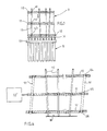
- the test adapter 9 shown in detail and in section in FIG. 1 has three guide plates 10, 11, 12 which are arranged at intervals from one another and are directed parallel and horizontally to one another.
- these three guide plates 10-12 there are guide bores, such as 41, 42, 43 for metallic, straight, needle-like contact pins 13, which form so-called rigid pins, are arranged, each of which has its rear ends seated on a metallic contact 16 serving for its electrical connection.
- These contacts 16 are the heads of piston members of spring contact pins 15, which have sleeves, in each of which a spring loading the respective piston member is arranged for resilient support of the contact pins 13.
- These spring contact pins 15 are constantly electrically connected to a test or test device, not shown, which is automatically programmable for the respective type of test objects in a known manner, so that each test object that is contacted by the relevant contact pins 13 of the test adapter 9 is free of errors can be tested. It can also be provided that measurements are also carried out on the respective test object by means of the testing or testing device, for example on components of assembled printed circuit boards.
- the contacts 16 are arranged at all grid points of a predetermined grid.
- Three of the illustrated contact pins 13 are used to contact test points of the respective test specimen located outside the grid and are therefore oriented somewhat obliquely relative to the planes of the guide plates 10, 11, 12 by their guide bores being offset somewhat from one another, but still forming a straight row, so that the contact pins in them are not bent.
- the contact pins are mounted in the guide bores of the guide plates 10, 11, 12 with plain bearing play, so that they make contact of test objects can be axially displaced by them.
- One of the contact pins shown is directed vertically and is therefore directed vertically to the parallel, horizontal, flat guide plates 10, 11, 12.
- the guide bores in the rear (lower) guide plate 12 of the test adapter 9 are all located at grid points of the grid and are thus aligned with the contacts 16 lying opposite them.
- guide bores such as 43, are arranged only at the locations in the rear guide plate 12. where contact pins 13 are to be received.
- this rear guide plate 12 can also have guide bores at all grid points of the relevant grid in order to be able to use them for test objects with different test point arrangements.
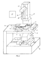
- FIG. 2 shows an automatic drilling machine for drilling all the guide plates of a test adapter required for the respective test specimen type, or all guide plates with the exception of the rear plate, in a schematic and schematic manner. If the type of test object changes, then new guide plates 10, 11 or 10, 11, 12 have to be drilled on this automatic drill.
- the automatic drill has a frame 20 which has two tables 21, 22 which are fixedly spaced one above the other and an upright stand 23.
- the stand 23 is horizontal by means of a cross slide arrangement 24 having two slides 25 and 26 In two mutually perpendicular directions (x and y directions) by means of servomotors, not shown, so displaceable that a borne by the stand 23 and on it vertically up and down adjustable drilling device 28 with a drill 28 'over any desired location from this embodiment three superposed guide plates 10, 11 and 12 existing plate assembly is movable to drill in them guide hole rows, such as 41, 42, 43, for contact pins 13 to be used (Fig. 1) in a single vertical downward drilling operation. A contact pin 13 was previously inserted into the row of guide bores 41, 42, 43.
- FIG. 1 Another row of guide bores 41 ', 42', 43 'is shown, into which a contact pin is only to be inserted subsequently.
- These guide plates 10 to 12 are carried by a support 14 which is fixedly arranged on the table 22 and in the area where the drill 28 'can drill rows of holes in the guide plates has a recess which allows the drill 28' to penetrate.
- the lowest guide plate 12 is fixedly arranged on this support 14 and the two other guide plates 10, 11 rest on it.
- Each of these two guide plates 10 and 11 can be adjusted horizontally in two mutually perpendicular directions by means of an actuator 30, 31 assigned to it.
- the two actuators 30, 31 together form an actuating device and each have a cross slide arrangement, which cannot be seen, in each housing, with two horizontally guided straight lines each have an electric servomotor, preferably a stepper motor movable carriage.
- One carriage is arranged on the other carriage. The same applies to the slides 25 and 26 that the sled 26 is arranged on the sled 25.
- the servomotors of the cross slide arrangement 24, as well as the servomotors of the slides of the two cross slide arrangements of the actuating device 30, 31 are controlled by a microprocessor 29 in a programmed manner to produce all guide bores in the guide plates 10, 11 and 12.
- the cross slide arrangement of the actuator 30 serves to move the uppermost guide plate 10 in the x and y directions, which are horizontal and perpendicular to one another.
- the cross slide arrangement of the actuator 31 serves to move the middle guide plate 11 in horizontal x and y directions.
- the carriage 25 is used to move the stand 23 in the y direction and the carriage 26 in the x direction.
- the lowest clamped guide plate 12 is the guide plate, the guide bores of which are to be drilled in a grid.
- the other two guide plates 10, 11 must be partially provided with guide holes that are out of grid.
- the coordinates of all guide bores are stored in the microprocessor 29.
- This microprocessor controls the servomotors of the Cross slide arrangement 24 in such a way that the longitudinal axis of the drill 28 'of the drilling device 28 is brought into alignment with the guide holes to be drilled in the grid in the lowermost guide plate 12, the program expediently running such that the displacement paths of the drilling device 28 are as short as possible.
- the four servomotors of the cross slide arrangements of the actuators 30 and 31 controlled so that, if the guide holes to be made in the next drilling process are not already in alignment with one another, this occurs with this row of guide holes to be made in alignment with one another and then moves the drilling device 28 vertically downward by moving the carriage 31 'carrying it and starting the drilling device 28 vertically until the relevant row of holes in the guide plates 10 to 12 is drilled.
- the carriage 31 'again moves up automatically to its starting position and the stand 23 is moved such that the drill 28' of the drilling device 28 is aligned with the longitudinal axes of the guide bores of the next row of holes to be produced, after or already during the movement of the stand 23, the two upper guide plates 10, 11, if necessary, before drilling through the adjusting device 30, 31 controlled by the microprocessor 29, preferably by a program control device, be moved by him into positions in which the longitudinal axes of the guide bores to be produced are aligned with one another, so that by moving the slide 31 'downwards with the drilling device 28 switched on, this row of guide bores are drilled in a single, vertically downward drilling operation can. It also happens more or less often that the guide plates 10 and 11 do not have to be moved between two drilling operations. But every time they have to be moved for a drilling operation before it starts, this is carried out under the control of the microprocessor 29.
- the guide plates 10 to 12 lie on top of one another, since then the guide plates 11 and 12 have favorable support for drilling. However, it may also be provided that they are arranged vertically one above the other at relatively short intervals.
- the ray set applies to the relative displacement of the guide plates 10 and 11 with respect to one another. So if the guide plates 10 and 11 are at a and b from the guide plate 12 and the guide plate 10 is displaced by the actuator 31 in a certain horizontal direction by the distance d, then the guide plate 11 in the same direction by the distance dxb / a (d times b / a). It is therefore also possible to provide for the signals fed to the two servomotors of the actuator 30, which serve to multiply the guide plate 10 by the distances e and f in order to obtain the total displacement d for the actuation of the two servomotors of the actuator 31 by b / a.
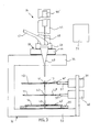
- the mounting device 36 has a frame 32 which has two fixed tables 33 and 34 at a distance from one another.
- the guide plate 12 is fastened on a support 35, which is perforated below its field having the guide bores, so that the contact pins can penetrate a short distance through the guide bores in the lower guide plate 12.
- the guide plates 10 and 11 are held on actuators 39, 40, which are displaced horizontally by means of a cross slide arrangement, each arranged in a housing, with associated actuators, which can be controlled by a microprocessor 29 according to a program stored in it.
- These guide plates 10, 11 are each held on a rigid arm 37, 37 'carrying them, each of which is fastened to a horizontally guided slide of the adjusting device 30, 31.
- These two slides are the upper slides, not shown, of the cross slide arrangements of the actuators 30, 31, the lower slides of which can be adjusted horizontally and perpendicularly to the upper slides.
- the guide plates 10 and 11 by the two arranged in the actuators 39 and 40 cross slide arrangements in connection with their associated actuators parallel and horizontal to each other and to the guide plate 12 both in the horizontal x-direction parallel to the image plane and in the horizontal y perpendicular to the image plane -Direction can be adjusted.
- the possible changes in position need only be relatively small. They are used to bring those guide bores, such as 41 and 42, which are not in alignment with one another prior to the respective drilling of a row of guide bores, before being fitted with a contact pin 13, so that the relevant guide bores 41 and 42 of the guide plates 10 and 11 are in alignment with the associated guide bore 43 in the guide plate 12.
- a cross slide arrangement 53 is arranged on the upper table 34, the lower slide 44 of which is guided straight on the table 34 in the horizontal direction parallel to the image plane and can be displaced by a servomotor (not shown).
- the upper carriage 45 can be moved back and forth on the lower carriage 44 in a horizontal, straight direction perpendicular to the image plane by means of a servomotor, also not shown, and carries a rigid stand 46, which is fixedly attached to it, on which a lifting or working cylinder 46 'carries a vertical bumper or stamp 48 in the vertical position.
- a tube 47 is also held on the stand 46, which serves for the successive supply of contact pins 13 to a guide tube 49 which is expanded in the shape of a funnel in the upper region and whose circular cylindrical guide channel adjoining the funnel has a clear diameter which is slightly larger than the diameter of the contact pins 13 is.
- the guide tube 49 is immovably connected to the stand 46.
- the servomotors of the carriages 44, 45 of the cross-slide arrangement 53 are operated by a microprocessor in a program-controlled manner, which servomotors can also preferably be electric stepper motors, that the guide tube 49 is successively aligned with one another in each case Guide plate 12 existing guide hole comes into which a contact pin 13 is to be inserted.
- the microprocessor 29 controls the servomotors of the cross slide arrangements located in the actuators 39, 40 simultaneously or thereafter or beforehand in such a way that the guide bores associated with the relevant guide bore, for example the guide bore 43, the guide plate 12, for example the guide bores 41, 42, come into alignment in the guide plates 10, 11 with the relevant guide bore in the guide plate 12, if this was not already the case. Then, through the tube 47, a contact pin 13 is attached to this row of guide bores, for example the row of guide bores 41, 42, 43 directed guide tube 49 and falls with vertical alignment and alignment with this guide bore row to it and at least in the top guide bore and possibly also through the other two guide bores of this guide bore row in its final, in Fig. 3 position shown using an example.
- This assembly process can be fully automatically controlled by the microprocessor 29 and requires very little time per contact pin 13.
- the contact pins 13 are needle-like and, in addition to their tips used for contacting test specimens, have a circular cylindrical shape. However, contact pins can also be provided, at the rear or front ends of which widened heads are provided. In such a case, the guide plates 10 to 12 should be arranged so that the widened ends of the contact pins are present at the rear ends when they are inserted.
- these guide plates equipped with contact pins can be removed from the mounting device shown and installed in the test adapter, it being only necessary to ensure that the contact pins cannot fall out of the guide bores. If the contact pins have no widened ends, one can prevent the contact pins from falling out when transferring and installing the assembled ones Provide guide plates 10 to 12 in the test adapter so that the contact pins sit with their lower ends on a plate placed on the table 33 during assembly, which is brought together with the guide plates to the test adapter and is only removed there when these guide plates 10 to 12 in the intended positions above the spring contact pins 15 (Fig. 1) are arranged. You then just pull the plate out to the side.
- the guide plates 10 and 11 are the guide plates 10 and 11, but there may also be more guide plates - by means of a separate actuator 39, 40 each parallel to itself in the x and y directions 4, the guide plates 10, 11, 12, regardless of whether there are three or more guide plates, can be coupled in motion by articulated rods 51 in the manner of a spatial parallelogram guide , wherein this coupling of movement acts in the planes of the guide plates both in the x-direction and in the y-direction, that is to say to move these guide plates as desired parallel to themselves by the only required actuator 40 'in such a way that before carrying out an assembly process a guide hole row whose guide holes are aligned en.
- the articulated rods are connected to the guide plates 10, 11 and 12 in a practically play-free manner by means of ball joints 54, 55 and 56.
- the articulated rods 51 penetrate openings in the two outer guide plates 10 and 12 and in these holes ball sockets are inserted from the outside, in which spherical surface-shaped end sections of the articulated rods are mounted in the manner of ball joints.
- the articulated rods 51 each have a spherical zone, which are each slidably mounted in a spherical zone-shaped section of the guide plate 11.
- they can be made, for example, in two parts.
- hinge rods 51 cause, as can be readily recognized, that the guide holes of each row of guide holes to be drilled are always arranged in a straight row according to the jet set, so that if only the guide hole in the middle guide plate 11 is aligned with the associated guide hole in the lower one Guide plate 12 is brought, then the associated guide holes in the upper guide plate 10 is aligned with these two guide holes.
Landscapes
- Engineering & Computer Science (AREA)
- Manufacturing & Machinery (AREA)
- Microelectronics & Electronic Packaging (AREA)
- Physics & Mathematics (AREA)
- General Physics & Mathematics (AREA)
- Measuring Leads Or Probes (AREA)
Applications Claiming Priority (2)
| Application Number | Priority Date | Filing Date | Title |
|---|---|---|---|
| DE4011434 | 1990-04-09 | ||
| DE19904011434 DE4011434A1 (de) | 1990-04-09 | 1990-04-09 | Verfahren und vorrichtung zum bohren und/oder bestuecken der fuehrungsplatten eines pruefadapters |
Publications (2)
| Publication Number | Publication Date |
|---|---|
| EP0451690A2 true EP0451690A2 (fr) | 1991-10-16 |
| EP0451690A3 EP0451690A3 (en) | 1993-05-26 |
Family
ID=6404057
Family Applications (1)
| Application Number | Title | Priority Date | Filing Date |
|---|---|---|---|
| EP19910105289 Withdrawn EP0451690A3 (en) | 1990-04-09 | 1991-04-03 | Process and device for drilling and/or equipping of the guiding plates of a test adaptor |
Country Status (2)
| Country | Link |
|---|---|
| EP (1) | EP0451690A3 (fr) |
| DE (1) | DE4011434A1 (fr) |
Cited By (2)
| Publication number | Priority date | Publication date | Assignee | Title |
|---|---|---|---|---|
| DE4323276A1 (de) * | 1993-07-12 | 1995-01-19 | Mania Gmbh | Vollmaterialadapter |
| WO2001057541A1 (fr) * | 2000-02-04 | 2001-08-09 | Atg Test Systems Gmbh & Co Kg | Adaptateur pour verifier des cartes de circuits et aiguille de controle pour adaptateur de ce type |
Family Cites Families (3)
| Publication number | Priority date | Publication date | Assignee | Title |
|---|---|---|---|---|
| EP0144682B1 (fr) * | 1983-11-07 | 1989-08-09 | Martin Maelzer | Adaptateur pour un dispositif de test pour des circuits imprimés |
| DE3539720A1 (de) * | 1985-11-08 | 1987-05-14 | Martin Maelzer | Adapter fuer ein leiterplattenpruefgeraet |
| DE3736689A1 (de) * | 1986-11-18 | 1988-05-26 | Luther Erich | Adapter fuer ein leiterplattenpruefgeraet |
-
1990
- 1990-04-09 DE DE19904011434 patent/DE4011434A1/de not_active Withdrawn
-
1991
- 1991-04-03 EP EP19910105289 patent/EP0451690A3/de not_active Withdrawn
Cited By (3)
| Publication number | Priority date | Publication date | Assignee | Title |
|---|---|---|---|---|
| DE4323276A1 (de) * | 1993-07-12 | 1995-01-19 | Mania Gmbh | Vollmaterialadapter |
| US5977786A (en) * | 1993-07-12 | 1999-11-02 | Mania Gmbh & Co. | Adapter including solid body |
| WO2001057541A1 (fr) * | 2000-02-04 | 2001-08-09 | Atg Test Systems Gmbh & Co Kg | Adaptateur pour verifier des cartes de circuits et aiguille de controle pour adaptateur de ce type |
Also Published As
| Publication number | Publication date |
|---|---|
| DE4011434A1 (de) | 1991-10-10 |
| EP0451690A3 (en) | 1993-05-26 |
Similar Documents
| Publication | Publication Date | Title |
|---|---|---|
| DE3038665C2 (de) | Prüfeinrichtung zum Überprüfen von mit Leiterbahnen versehenen Leiterplatten | |
| EP2269757B1 (fr) | Appareil de brasage d'un connecteur et d'une cellule solaire avec une unité de nettoyage | |
| EP0026824B2 (fr) | Adaptateur pour un dispositif pour le contrôle électronique de plaquettes à circuit imprimé | |
| DE3886979T2 (de) | Stanzvorrichtung für dünne Platten und in der Vorrichtung verwendete Stanzeinheiten. | |
| DE69123290T2 (de) | Inspektionsgerät für gedruckte Leiterplatten | |
| DE19503329C2 (de) | Testvorrichtung für elektronische Flachbaugruppen | |
| DE19623470C2 (de) | Automatisches Leitungsverzweigergerät | |
| EP0344654A2 (fr) | Procédé et adaptateur de test pour contacter des éléments à tester | |
| DE2628428C3 (de) | Adapter zum Verbinden von Anschluß- und/oder Prüfpunkten einer Baugruppe mit einer Mefischaltung | |
| EP0144682B1 (fr) | Adaptateur pour un dispositif de test pour des circuits imprimés | |
| EP3240123B1 (fr) | Dispositif de changement d'outil de sertissage et procede de changement d'un premier outil de sertissage dispose dans un processus dans une presse de sertissage contre un second outil de sertissage | |
| EP1902325B1 (fr) | Dispositif de test pour tester des composants électroniques | |
| EP0222345B1 (fr) | Méthod de test d'un circuit imprimé | |
| EP0331163A1 (fr) | Dispositif de contact pour dispositif de test pour tester des cartes imprimées ou similaires | |
| EP0451690A2 (fr) | Procédé et dispositif de forage et/ou d'équipement des plaques de guidage d'un adaptateur d'essai | |
| WO2001057541A1 (fr) | Adaptateur pour verifier des cartes de circuits et aiguille de controle pour adaptateur de ce type | |
| DE2344634C3 (de) | Stifteinsetzvorrichtung für an Textilmaschinen, insbesondere an Rundstrickmaschinen, vorgesehene Mustertrommeln | |
| DE3906691A1 (de) | Kontaktiervorrichtung fuer pruefvorrichtungen zum pruefen von leiterplatten oder dgl. | |
| DE19646252A1 (de) | Prüfvorrichtung | |
| DE1499685B1 (de) | Verfahren und vorrichtung zur verdrahtung von kernmatrizen | |
| DE69529918T2 (de) | Verfahren und einrichtung zum bewegen, insbesondere zum ersetzen von substratplatten in einer bestückungseinrichtung | |
| DE102019122424A1 (de) | Anpassbare Werkstückhaltevorrichtung | |
| DE3834049C2 (fr) | ||
| DE102008023614B3 (de) | Verfahren zum automatischen Positionieren von Unterstützungsstiften und Bestückautomat | |
| DE102019123099B3 (de) | Vorrichtung und Verfahren zum Herstellen von Schaltmodulen mit einem Gehäuse und zumindest einer darin eingeführten Elektronikkomponente |
Legal Events
| Date | Code | Title | Description |
|---|---|---|---|
| PUAI | Public reference made under article 153(3) epc to a published international application that has entered the european phase |
Free format text: ORIGINAL CODE: 0009012 |
|
| AK | Designated contracting states |
Kind code of ref document: A2 Designated state(s): DE FR GB IT |
|
| PUAL | Search report despatched |
Free format text: ORIGINAL CODE: 0009013 |
|
| AK | Designated contracting states |
Kind code of ref document: A3 Designated state(s): DE FR GB IT |
|
| STAA | Information on the status of an ep patent application or granted ep patent |
Free format text: STATUS: THE APPLICATION IS DEEMED TO BE WITHDRAWN |
|
| 18D | Application deemed to be withdrawn |
Effective date: 19931101 |