EP0451696A2 - Video phone unit - Google Patents
Video phone unit Download PDFInfo
- Publication number
- EP0451696A2 EP0451696A2 EP91105307A EP91105307A EP0451696A2 EP 0451696 A2 EP0451696 A2 EP 0451696A2 EP 91105307 A EP91105307 A EP 91105307A EP 91105307 A EP91105307 A EP 91105307A EP 0451696 A2 EP0451696 A2 EP 0451696A2
- Authority
- EP
- European Patent Office
- Prior art keywords
- picture
- party
- video phone
- photographed
- selecting
- Prior art date
- Legal status (The legal status is an assumption and is not a legal conclusion. Google has not performed a legal analysis and makes no representation as to the accuracy of the status listed.)
- Withdrawn
Links
- 230000004048 modification Effects 0.000 description 11
- 238000012986 modification Methods 0.000 description 11
- 238000010586 diagram Methods 0.000 description 7
- 230000035807 sensation Effects 0.000 description 6
- 230000005540 biological transmission Effects 0.000 description 1
- 239000004065 semiconductor Substances 0.000 description 1
Images


Classifications
-
- H—ELECTRICITY
- H04—ELECTRIC COMMUNICATION TECHNIQUE
- H04N—PICTORIAL COMMUNICATION, e.g. TELEVISION
- H04N7/00—Television systems
- H04N7/18—Closed-circuit television [CCTV] systems, i.e. systems in which the video signal is not broadcast
-
- H—ELECTRICITY
- H04—ELECTRIC COMMUNICATION TECHNIQUE
- H04N—PICTORIAL COMMUNICATION, e.g. TELEVISION
- H04N7/00—Television systems
- H04N7/14—Systems for two-way working
- H04N7/141—Systems for two-way working between two video terminals, e.g. videophone
- H04N7/147—Communication arrangements, e.g. identifying the communication as a video-communication, intermediate storage of the signals
-
- H—ELECTRICITY
- H04—ELECTRIC COMMUNICATION TECHNIQUE
- H04N—PICTORIAL COMMUNICATION, e.g. TELEVISION
- H04N7/00—Television systems
- H04N7/14—Systems for two-way working
- H04N7/141—Systems for two-way working between two video terminals, e.g. videophone
- H04N7/148—Interfacing a video terminal to a particular transmission medium, e.g. ISDN
Definitions
- the present invention relates to a video phone unit with a television camera.
- the moving picture of one speaker is photographed by a movable television camera before being transmitted to the other speaker.
- the speaker can not watch the television picture taken by the camera at his end of the line because the camera is secured to the body of the telephone. That is, the speaker can not select the area of which the picture is to be taken.
- Some types of television cameras can stand apart from the body of the telephone, but the television picture taken by the television camera can not be viewed by the speaker on the photographing side.
- a video phone unit for transmitting still or moving pictures between one party and an other party, comprising: receiving means (4, 5) for receiving a picture transmitted from the other party; photographing means (2, 21, 32, 51, 61) for photographing a subject to producing a photographed picture on one party side, the photographing means (2, 21, 32, 51, 61) being movable; detecting means (8, 23, 41) for detecting whether the photographing means (2, 21, 32, 51, 61) is immobile or mobile and generating either a first detecting signal indicating that the photographing means (2, 21, 32, 51, 61) is in a mobile state or a second detecting signal indicating that the photographing means (2, 21, 32, 51, 61) is immobile; first selecting means (9, 35) for selecting either the received picture at the receiving means (4, 5) or the photographed picture made at the photographing means (2, 21, 32, 51, 61) after receiving the first or second detecting signal provided from the detecting means (8, 23, 41);
- the video phone is divided into the photographing means (2, 21, 32, 51, 61) and a video phone body comprising the other means.
- the movable photographing means (2, 21, 32, 51, 61) is attached to the video phone body in an immobile state so that the first selecting means (9, 35) selects a received picture provided from the other party after receiving a second signal from the detecting means (8, 23, 41). Therefore, the received picture is displayed in the displaying means (12, 36) through the receiving means and the first selecting means (9, 35). Also, the photographed picture photographed in the photographing means (2, 21, 32, 51, 61) is transmitted to the other party through the transmitting means (6, 7). In other words, both parties are able to telecommunicate with each other while viewing each others faces.
- a second selecting means (25) for selecting either arbitrary pictures or the photographed picture taken by the photographing means (2, 21, 32, 51, 61) when the first or second detecting signal is provided from the detecting means (8, 23, 41) and transmitting the selected picture to the other party through the transmitting means (6, 7).
- the second selecting means (25) stops transmitting the photographed picture taken in the photographing means (2, 21, 32, 51, 61) to the other party when the first detecting signal is provided from the detecting means (8, 23, 41), while the second selecting means (25) transmits the photographed picture to the other party when the second detecting signal is provided from the detecting means (8, 23, 41).
- an internal memory means (24) for memorizing in advance a prescribed picture transmitted to the other party through the transmitting means (6, 7) instead of the photographed picture taken in the photographing means (2, 21, 32, 51, 61) while the second selecting means (25) stops transmitting the photographed picture to the other party.
- the other party when the movable photographing means (2, 21, 32, 51, 61) is set apart from the video phone body by one party, the other party receives the picture memorized in the internal memory means (24) on one party side instead of the photographed picture taken in the photographing means (2, 21, 32, 51, 61) on that side. Therefore, the other party always impart an agreeable sensation during the telecommunication with one party because the other party does not receive an unpleasant flickering picture.
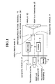
- Fig. 1 is a block diagram of a video phone according to the present invention, showing a first embodiment for achieving the first object.
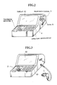
- Fig. 2 is a diagonal view of the video phone shown in Fig. 1 when a television camera is attached to a video phone body.
- Fig. 3 is a diagonal view of the video phone shown in Fig. 1 when the television camera is set apart from the video phone body.
- Fig. 4 is a block diagram of a video phone according to the present invention, showing a second embodiment for achieving the first and second objects.
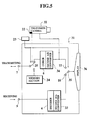
- Fig. 5 is a block diagram of of a video phone according to the present invention, showing a third embodiment for achieving the first and second objects.
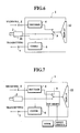
- Fig. 6 is a block diagram of a video phone according to the present invention, showing a fourth embodiment for achieving the first object by using an operating switch.
- Fig. 7 is a block diagram of a video phone according to the present invention, showing a fifth embodiment for achieving the first object by using a hook and a reset switch.
- Fig. 8 is a block diagram of a television camera shown in Fig. 1, showing a second modification of the camera.
- Fig. 9 is a block diagram of a television camera shown in Fig. 1, showing a third modification of the camera.
- FIG. 1 A first preferred embodiment of a video phone according to the present invention is described with reference to Figs. 1 to 3.
- the video phone for transmitting still or moving pictures between one party and an other party comprises a video phone body 1 and a television camera 2 for photographing a still or moving picture and attached to the video phone body 1, the television camera 2 being movable and capable of being easily set apart from the video phone body 1.
- the video phone body 1 comprises: a telephone receiver 3 for telecommunicating with the other party by voice; a decoder 4 for expanding a still or moving picture received from the other party through a receiving terminal 5, the picture being called a received picture and compressed for improving the efficiency of the transmission between one party and the other party; a coder 6 for compressing a still or moving picture taken by the television camera 2 to be transmitted to the other party through a transmitting terminal 7 with high efficiency, the picture being called a photographed picture; a hook 8 for hooking the camera 2 and generating a first detecting signal when the camera 2 is set apart from the hook 8 in a mobile state and a second detecting signal when the camera 2 is attached to the hook 8 in an immobile state, the camera 2 being easily attached or set apart from the hook 8; a changeover switch 9 for selecting the received picture transmitted through a received picture terminal 10 when the second detecting signal is provided from the hook 8 and for selecting the photographed picture made in the camera 2 when the first detecting signal is provided from the hook 8; a display 12 for
- the camera 2 is provided with a first analog-to-digital converter 14 for converting the photographed picture which is analog to a digital photographed picture. Therefore, the camera 2 provides the digital photographed picture to the changeover switch 9.
- the still or moving picture expanded in the decoder 4 is a digital received picture so that the decoder 4 provides the digital received picture to the changeover switch 9.
- the changeover switch 9 comprises a 54/74F157A Quad 2-Input Multiplexer purchased from the National Semiconductor Co. LTD.
- the multiplexer handles digital signals.
- the display 12 is provided with a first digital-to-analog converter 15 for converting the digital picture selected in the changeover switch 9 to an analog picture to display in the display 12.
- the changeover switch 9 selects the photographed picture under control of the first detecting signal provided from the hook 8 when the camera 7 is removed from the hook 8, while the changeover switch 9 selects the received picture under control of the second detecting signal provided from the hook 8 when the camera 7 is attached to the hook 8.
- the term “photographed picture” is used for the picture made in the camera 2 for the sake of convenience. Also, the term “received picture” is used for the picture transmitted from the other party and received at the receiving terminal 5 for the sake of convenience.
- the camera 2 is attached to the video phone body 1 to photograph the one party as shown in Fig. 2 so that a second detecting signal is generated in the hook 8 and provided to the changeover switch 9.
- the camera 2 transmits the photographed picture through both the coder 6 and the transmitting terminal 7 to the other party.
- a received picture received at the receiving terminal 5 is displayed in the display 12 through the decoder 4 and the changeover switch 9 because the changeover switch 9 receives the second detecting signal from the hook 8 and selects the received picture for transmitting to the display 12. Therefore, both parties are able to talk with each other while viewing each received picture.
- the hook 8 detects that the camera 2 is set apart from the video phone body 1 and provides a first detecting signal to the changeover switch 9 so that the switch 9 changes the selection from the received picture to the photographed picture.
- the one party can select the photographed area arbitrarily while viewing the photographed picture.
- a video phone of the second embodiment according to the present invention comprises a video phone body 20 and a television camera 21 attached to the video phone body 20, the camera 21 being movable and capable of being easily set apart from the video phone body 20.
- the television camera 21 is provided with the first analog-to-digital converter 14 and an operating switch 22 which is integrally formed with the camera 21, the operating switch 22 being operated by the one party at will.
- the video phone body 20 comprises: the telephone receiver 3; a hook 23 for hooking the camera 21 and generating a first detecting signal when the camera 21 is removed from the hook 23 in a mobile state and a second detecting signal when the camera 21 is attached to the hook 23 and is immobile; the decoder 4; the coder 6; an internal memory section 24 for memorizing in advance a prescribed picture; a second changeover switch 25 for
- the operating switch 22 is operated to change the selection in the second changeover switch 25 from the picture memorized in the internal memory section 24 to the photographed picture when the camera 21 is set immobily state in a new position and the focus of the camera 21 is adjusted in spite of being removed from the hook 23.
- the second changeover switch 25 also comprises a 54/74F157A Quad 2-Input Multiplexer.
- the photographed picture is transmitted to the other party through the coder 6 and the second changeover switch 25 because a second detecting signal is provided from the hook 23 to the second changeover switch 25. Therefore, the other party does not receive an unpleasant sensation because the picture is not flickering.
- the picture memorized in the internal memory section 24 is transmitted to the other party through the second changeover switch 25 because a first detecting signal is provided from the hook 23 to the second changeover switch 25. Therefore, the photographed picture which is flickering in sychronization with the flickering of the camera 21 is not transmitted to the other party.
- the other party can receive the memorized picture which does not impart an unpleasant sensation because the picture is not flickering.
- the second changeover switch 25 is changed its selection from the memorized picture to the photographed picture because a control signal generated by the operating switch 22 is provided to the second changeover switch 25.
- the operating switch 22 can be operated by the one party at will.
- the video phone of the second embodiment can transmit only a non-flickering picture to the other party so that only a pleasant sensation is imparted.
- the one party can transmit a new and meaningful picture quickly so that the communication between the parties is comfortable.
- the video phone be provided with an external memory instead of the internal memory section 24.
- a picture memorized in the external memory is transmitted to the other party through an input terminal and the second changeover switch 25.
- a video phone of the third embodiment according to the present invention comprises a video phone body 31 and a television camera 32 provided with the operating switch 22.
- the television camera 32 is movable and capable being set apart from the video phone body 31. It provides a photographed picture to the video phone body 31.
- the video phone body 31 comprises: the telephone receiver 3; the operating keyboard 13; the hook 23; the decoder 4; a second digital-to-analog converter 33 for converting the digital received picture expanded at the decoder 4 to the analog received picture; a second analog-to-digital converter 34 for converting the analog photographed picture provided from the camera 32 to the digital photographed picture; the coder 6 for compressing the photographed picture converted at the second analog-to-digital converter 34; the internal memory section 24; the second changeover switch 25;
- a first analog changeover switch 35 for selecting the analog received picture converted at the second digital-to-analog converter 33 when the second detecting signal is provided from the hook 23 and selecting the analog photographed picture photographed in the camera 32 when the first detecting signal is provided from the hook 23; a display 36 for displaying the analog received picture or the analog photographed picture selected in the first analog changeover switch 35; and the first analog changeover switch 35, comprising a HI-518 CMOS high speed analog multiplexer purchased from the HARRIS semiconductor products division.
- the multiplexer handles analog signals.
- a received picture is transmitted from the other party to the receiving terminal 5 on the one party side.
- the received picture is consist of digital signals for transmitting the signal between the one party and the other party.
- the display 12 can be operated by receiving only analog signals. Therefore, the digital received picture is converted to an analog received picture at the second digital-to-analog converter 33 after being expanded in the decoder 4. Then, the analog received picture is provided to the analog changeover switch 35.
- a photographed picture is produced in the camera 32 and the obtained photographed picture is analog. Then, the analog photographed picture is provided to the analog changeover switch 35 without being converted to a digital picture.
- the analog changeover switch 35 handles only analog pictures. Therefore, the switch 35 selects one analog picture to send the picture to the display 36 according to a prescribed protocol as described in Fig. 4.
- the analog photographed picture is transmitted to the other party after being converted at the second analog-to-digital converter 34 when the second changeover switch 25 selects the photographed picture according to the prescribed protocol as described in Fig. 4.
- the received picture or the photographed picture are displayed in the display 36 alternatively to achieve the first object in the same manner as the video phone with the digital changeover switch 9.
- the photographed picture or a picture memorized in the internal memory section 24 is transmitted to the other party alternatively to achieve the second object.
- the video phone of the fourth embodiment as shown in Fig. 6 is provided with an operating switch 41 instead of the hook 8.
- the operating switch 41 is integrally formed with the television camera 2 and operated by the one party by hand.
- the changeover switch 9 selects a photographed picture taken in the camera 2 when a first operating signal provided from the operating switch 41 is provided to the switch 9 and selects a received picture transmitted from the other party when a second operating signal provided from the operating switch 41 is provided to the switch 9.
- the one party can select the picture displayed in the display 12 at will. This means that the one party can view and confirm the received picture in the display 12 when the camera 41 is set apart from the video phone unit 1, if necessary.
- the video phone of the fifth embodiment as shown in Fig. 7 further includes an reset switch 42 for changing over the selection of the changeover switch 9 by the one party.
- the one party can select the picture displayed in the display 12 at will in the same manner as the video phone of the fourth embodiment as shown in Fig. 6.
- a television camera 51 of the second modification comprises: a lens 52 for focusing incident light reflected from a subject; a video device 53 for converting the incident light focused in the lens 52 to a video signal, the video signal being transmitted to the changeover switch 9 in the video phone body 1; an on-off switch 54 trough which the video signal converted in the video device 53 is passed when the switch 54 receives the first detecting signal from the hook 8; and a display 55 for displaying the video signal passing through the switch 54.
- the incident light reflected from the subject for photography is converted to a video signal at the video device 53 after being focused at the lens 52.
- the video signal obtained at the video device 53 is provided to the display 55 to display the subject to the one party when the switch 54 is closed by receiving a first detecting signal from the hook 8.
- the one party can be away from the video phone body 1 because that party can always view the subject for photography in the display 55 attached to the camera 51. This means that a photographed area for photographing a desired subject is expanded.
- the video phone body 1 be provided with the the operating switch 41 as shown in Fig. 6 instead of the hook 8.
- a television camera of a third modification according to the present invention ia compared with the television camera 2 of the first modification as shown in Fig. 1 and is described with reference to Fig. 9.
- a television camera 61 of the third modification comprises: a lens 62 for focusing incident light reflected from a subject for photography; a spectroscope 63 for dividing the incident light focused in the lens 62; a video device 64 for converting one part of the incident light divided in the spectroscope 63 to a video signal, the video signal transmitted to the changeover switch 9 in the video phone body 1 and the other party; a reflecting mirror 65 for reflecting the other part of the incident light divided in the spectroscope 63; and a finder 66 for displaying the other part of the incident light reflected in the reflecting mirror 65.
- the incident light reflected from the subject for photography is divided into two parts at the spectroscope 63 after being focused at the lens 62.
- One part of the incident light is converted to the photographed picture at the video device 64 to be provided to the changeover switch 9 in the video phone body 1 and the other party.
- the other part of the incident light is viewed by the one party through the finder 66 after being reflected at the reflecting mirror 65.
- the one party can view and confirm the subject for photography economically because the television camera 61 is provided with the finder 66 which is cheaper than the display 55. Also, the one party can be away from the video phone body 1 so that the photographed area for photographing the subjects is expanded in the same manner as in the second modification.
- the cameras 2, 21, 32 be an auto focus type for quickly adjusting the focus automatically and transmitting a new photographed picture to the other party.
- the cameras 2, 21, 32 be provided with a microphone for transmitting the surrounding sound or voice on the one party side with the photographed picture.
- the photographed picture be displayed at the one part of the displaying area of the display 12, 36 while the received picture is displayed at the other part of the displaying area of the displays 12, 36 when the changeover switches 9, 35 select the photographed picture.
- the photographed picture taken in the cameras 2, 21, 32 be transmitted to the video phone bodies 1, 31 in the radio communication.
Landscapes
- Engineering & Computer Science (AREA)
- Multimedia (AREA)
- Signal Processing (AREA)
- Computer Networks & Wireless Communication (AREA)
- Telephonic Communication Services (AREA)
- Two-Way Televisions, Distribution Of Moving Picture Or The Like (AREA)
Abstract
Description
- The present invention relates to a video phone unit with a television camera.
- Recently, the use of a video phone unit for transmitting a moving picture has been rapidly developing along with the increasing use of digital communication networks.
- Normally, in a conventional video phone unit, the moving picture of one speaker is photographed by a movable television camera before being transmitted to the other speaker.
- However, in the above conventional video phone unit, the speaker can not watch the television picture taken by the camera at his end of the line because the camera is secured to the body of the telephone. That is, the speaker can not select the area of which the picture is to be taken. Some types of television cameras can stand apart from the body of the telephone, but the television picture taken by the television camera can not be viewed by the speaker on the photographing side.
- Also, in the above conventional video phone unit, because a subject is photographed while the photographed picture is being transmitted, a flickering picture is transmitted when the television camera is moved. Therefore, a receiver feels unpleasant. This imparts a disagreeable sensation to the person viewing the picture at the receiving end.
- It is a first object of the present invention to provide a video phone unit in which an extended area can be photographed by the television camera and the television picture taken by the camera is easily viewed.
- It is a second object of the present invention to provide a video phone unit in which a picture imparting an agreeable sensation to the viewer can be transmitted when the television camera is moved.
- These objects are achieved in the present invention by the provision of a video phone unit for transmitting still or moving pictures between one party and an other party, comprising:
receiving means (4, 5) for receiving a picture transmitted from the other party;
photographing means (2, 21, 32, 51, 61) for photographing a subject to producing a photographed picture on one party side, the photographing means (2, 21, 32, 51, 61) being movable;
detecting means (8, 23, 41) for detecting whether the photographing means (2, 21, 32, 51, 61) is immobile or mobile and generating either a first detecting signal indicating that the photographing means (2, 21, 32, 51, 61) is in a mobile state or a second detecting signal indicating that the photographing means (2, 21, 32, 51, 61) is immobile;
first selecting means (9, 35) for selecting either the received picture at the receiving means (4, 5) or the photographed picture made at the photographing means (2, 21, 32, 51, 61) after receiving the first or second detecting signal provided from the detecting means (8, 23, 41);
displaying means (12, 36) for displaying one picture selected at the first selecting means (9, 35); and
transmitting means (6, 7) for transmitting the photographed picture provided by the photographing means (2, 21, 32, 51, 61) to the other party. - Also, it is preferable that the first selecting means (9, 35) selects the photographed picture made in the photographing means (2, 21, 32, 51, 61) when the first detecting signal is provided from the detecting means (8, 23, 41) and selects the received picture received in the receiving means (4, 5) when the second detecting signal is provided from the detecting means (8, 23, 41).
- In the above structure of the video phone according to the present invention, the video phone is divided into the photographing means (2, 21, 32, 51, 61) and a video phone body comprising the other means.
- Normally, the movable photographing means (2, 21, 32, 51, 61) is attached to the video phone body in an immobile state so that the first selecting means (9, 35) selects a received picture provided from the other party after receiving a second signal from the detecting means (8, 23, 41). Therefore, the received picture is displayed in the displaying means (12, 36) through the receiving means and the first selecting means (9, 35). Also, the photographed picture photographed in the photographing means (2, 21, 32, 51, 61) is transmitted to the other party through the transmitting means (6, 7). In other words, both parties are able to telecommunicate with each other while viewing each others faces.
- On the other hand, when the movable photographing means (2, 21, 32, 51, 61) is set apart from the video phone body by one party on one party side, the first selecting means (9, 35) changes its selection from the received picture to the photographed picture automatically because the photographing means (2, 21, 32, 51, 61) set apart from the video phone body is in the mobile state and the first selecting means (9, 35) receives a first detecting signal from the detecting means (8, 23, 41). Therefore, one party can directly view the photographed picture on his own side through the displaying means (12, 36). This means that one party can select the photographing area arbitrarily while confirming the photographed picture. That is, the video phone according to the present invention allows one party to photograph the subject over a wider area easily while viewing the photographed picture on his own side.
- Also, it is preferable to further include a second selecting means (25) for selecting either arbitrary pictures or the photographed picture taken by the photographing means (2, 21, 32, 51, 61) when the first or second detecting signal is provided from the detecting means (8, 23, 41) and transmitting the selected picture to the other party through the transmitting means (6, 7).
- Moreover, it is preferable that the second selecting means (25) stops transmitting the photographed picture taken in the photographing means (2, 21, 32, 51, 61) to the other party when the first detecting signal is provided from the detecting means (8, 23, 41), while the second selecting means (25) transmits the photographed picture to the other party when the second detecting signal is provided from the detecting means (8, 23, 41).
- Further, it is preferable to further include an internal memory means (24) for memorizing in advance a prescribed picture transmitted to the other party through the transmitting means (6, 7) instead of the photographed picture taken in the photographing means (2, 21, 32, 51, 61) while the second selecting means (25) stops transmitting the photographed picture to the other party.
- In the above structure of the video phone according to the present invention, when the movable photographing means (2, 21, 32, 51, 61) is set apart from the video phone body by one party, the other party receives the picture memorized in the internal memory means (24) on one party side instead of the photographed picture taken in the photographing means (2, 21, 32, 51, 61) on that side. Therefore, the other party always impart an agreeable sensation during the telecommunication with one party because the other party does not receive an unpleasant flickering picture.
- Fig. 1 is a block diagram of a video phone according to the present invention, showing a first embodiment for achieving the first object.
- Fig. 2 is a diagonal view of the video phone shown in Fig. 1 when a television camera is attached to a video phone body.
- Fig. 3 is a diagonal view of the video phone shown in Fig. 1 when the television camera is set apart from the video phone body.
- Fig. 4 is a block diagram of a video phone according to the present invention, showing a second embodiment for achieving the first and second objects.
- Fig. 5 is a block diagram of of a video phone according to the present invention, showing a third embodiment for achieving the first and second objects.
- Fig. 6 is a block diagram of a video phone according to the present invention, showing a fourth embodiment for achieving the first object by using an operating switch.
- Fig. 7 is a block diagram of a video phone according to the present invention, showing a fifth embodiment for achieving the first object by using a hook and a reset switch.
- Fig. 8 is a block diagram of a television camera shown in Fig. 1, showing a second modification of the camera.
- Fig. 9 is a block diagram of a television camera shown in Fig. 1, showing a third modification of the camera.
- A first preferred embodiment of a video phone according to the present invention is described with reference to Figs. 1 to 3.
- As shown in Figs. 1 to 3, the video phone for transmitting still or moving pictures between one party and an other party comprises a
video phone body 1 and atelevision camera 2 for photographing a still or moving picture and attached to thevideo phone body 1, thetelevision camera 2 being movable and capable of being easily set apart from thevideo phone body 1. - The
video phone body 1 comprises:
atelephone receiver 3 for telecommunicating with the other party by voice;
adecoder 4 for expanding a still or moving picture received from the other party through areceiving terminal 5, the picture being called a received picture and compressed for improving the efficiency of the transmission between one party and the other party;
acoder 6 for compressing a still or moving picture taken by thetelevision camera 2 to be transmitted to the other party through a transmittingterminal 7 with high efficiency, the picture being called a photographed picture;
ahook 8 for hooking thecamera 2 and generating a first detecting signal when thecamera 2 is set apart from thehook 8 in a mobile state and a second detecting signal when thecamera 2 is attached to thehook 8 in an immobile state, thecamera 2 being easily attached or set apart from thehook 8;
achangeover switch 9 for selecting the received picture transmitted through a receivedpicture terminal 10 when the second detecting signal is provided from thehook 8 and for selecting the photographed picture made in thecamera 2 when the first detecting signal is provided from thehook 8;
adisplay 12 for displaying either the received picture or the photographed picture selected by thechangeover switch 9; and
anoperating keyboard 13 for adjusting the voice transmitted through thetelephone receiver 3 or the picture displayed in thedisplay 12.
- The
camera 2 is provided with a first analog-to-digital converter 14 for converting the photographed picture which is analog to a digital photographed picture. Therefore, thecamera 2 provides the digital photographed picture to thechangeover switch 9. - The still or moving picture expanded in the
decoder 4 is a digital received picture so that thedecoder 4 provides the digital received picture to thechangeover switch 9. - The
changeover switch 9 comprises a 54/74F157A Quad 2-Input Multiplexer purchased from the National Semiconductor Co. LTD. The multiplexer handles digital signals. - The
display 12 is provided with a first digital-to-analog converter 15 for converting the digital picture selected in thechangeover switch 9 to an analog picture to display in thedisplay 12. - Also, the
changeover switch 9 selects the photographed picture under control of the first detecting signal provided from thehook 8 when thecamera 7 is removed from thehook 8, while thechangeover switch 9 selects the received picture under control of the second detecting signal provided from thehook 8 when thecamera 7 is attached to thehook 8. - In the above structure of the video phone, the operation is explained as follows.
- In following explanation, the term "photographed picture" is used for the picture made in the
camera 2 for the sake of convenience. Also, the term "received picture" is used for the picture transmitted from the other party and received at the receivingterminal 5 for the sake of convenience. - Normally, the
camera 2 is attached to thevideo phone body 1 to photograph the one party as shown in Fig. 2 so that a second detecting signal is generated in thehook 8 and provided to thechangeover switch 9. Thecamera 2 transmits the photographed picture through both thecoder 6 and the transmittingterminal 7 to the other party. At the same time, a received picture received at the receivingterminal 5 is displayed in thedisplay 12 through thedecoder 4 and thechangeover switch 9 because thechangeover switch 9 receives the second detecting signal from thehook 8 and selects the received picture for transmitting to thedisplay 12. Therefore, both parties are able to talk with each other while viewing each received picture. - On the other hand, when the one party want to transmit a different picture which is a photograph of a different subject, that party removes the
camera 2 from thevideo phone 1 as shown in Fig. 3. Therefore, in the conventional video phone, the one party can not recognize what thecamera 2 photographs because the photographed picture is transmitted to the other party and not transmitted to the one party. This means that the one party can not select the photographed area arbitrarily while viewing the photographed picture. However, in the present invention, thehook 8 detects that thecamera 2 is set apart from thevideo phone body 1 and provides a first detecting signal to thechangeover switch 9 so that theswitch 9 changes the selection from the received picture to the photographed picture. - Accordingly, the one party can select the photographed area arbitrarily while viewing the photographed picture. This means that the extended area can be photographed by the television camera.
- Next, a second embodiment is explained with reference to Fig. 4 for achieving the first object and the second object.
- The same reference code numbers are used in the following description and figures for the same elements described in the previous description and figures.
- A video phone of the second embodiment according to the present invention comprises a
video phone body 20 and atelevision camera 21 attached to thevideo phone body 20, thecamera 21 being movable and capable of being easily set apart from thevideo phone body 20. - The
television camera 21 is provided with the first analog-to-digital converter 14 and anoperating switch 22 which is integrally formed with thecamera 21, the operatingswitch 22 being operated by the one party at will. - The
video phone body 20 comprises:
thetelephone receiver 3;
ahook 23 for hooking thecamera 21 and generating a first detecting signal when thecamera 21 is removed from thehook 23 in a mobile state and a second detecting signal when thecamera 21 is attached to thehook 23 and is immobile;
thedecoder 4;
thecoder 6;
aninternal memory section 24 for memorizing in advance a prescribed picture;
a second changeover switch 25 for - (1) selecting the memorized picture in the
internal memory section 24 when the first detecting signal is provided from thehook 23 and - (2) selecting the photographed picture taken in the
camera 21 when the second detecting signal is provided from thehook 23 and transmitting the selected picture to the other party through the transmittingterminal 7. - The operating
switch 22 is operated to change the selection in the second changeover switch 25 from the picture memorized in theinternal memory section 24 to the photographed picture when thecamera 21 is set immobily state in a new position and the focus of thecamera 21 is adjusted in spite of being removed from thehook 23. - The second changeover switch 25 also comprises a 54/74F157A Quad 2-Input Multiplexer.
- In the above structure, when the
camera 21 is attached to thevideo phone unit 20, the photographed picture is transmitted to the other party through thecoder 6 and the second changeover switch 25 because a second detecting signal is provided from thehook 23 to the second changeover switch 25. Therefore, the other party does not receive an unpleasant sensation because the picture is not flickering. - When the
camera 21 is set apart from thevideo phone unit 20, the picture memorized in theinternal memory section 24 is transmitted to the other party through the second changeover switch 25 because a first detecting signal is provided from thehook 23 to the second changeover switch 25. Therefore, the photographed picture which is flickering in sychronization with the flickering of thecamera 21 is not transmitted to the other party. - In compensation, the other party can receive the memorized picture which does not impart an unpleasant sensation because the picture is not flickering.
- When the
camera 21 is set to a new photographing point to photograph a new subject and its focus is adjusted, the second changeover switch 25 is changed its selection from the memorized picture to the photographed picture because a control signal generated by the operatingswitch 22 is provided to the second changeover switch 25. The operatingswitch 22 can be operated by the one party at will. - Accordingly, the video phone of the second embodiment can transmit only a non-flickering picture to the other party so that only a pleasant sensation is imparted.
- Also, the one party can transmit a new and meaningful picture quickly so that the communication between the parties is comfortable.
- It is preferable that the video phone be provided with an external memory instead of the
internal memory section 24. In this case, a picture memorized in the external memory is transmitted to the other party through an input terminal and the second changeover switch 25. - Next, a third embodiment is explained with reference to Fig. 5 as follows
- A video phone of the third embodiment according to the present invention comprises a
video phone body 31 and atelevision camera 32 provided with the operatingswitch 22. - The
television camera 32 is movable and capable being set apart from thevideo phone body 31. It provides a photographed picture to thevideo phone body 31.
thevideo phone body 31 comprises:
thetelephone receiver 3;
the operatingkeyboard 13;
thehook 23;
thedecoder 4;
a second digital-to-analog converter 33 for converting the digital received picture expanded at thedecoder 4 to the analog received picture;
a second analog-to-digital converter 34 for converting the analog photographed picture provided from thecamera 32 to the digital photographed picture;
thecoder 6 for compressing the photographed picture converted at the second analog-to-digital converter 34;
theinternal memory section 24;
the second changeover switch 25; - A first
analog changeover switch 35 for selecting the analog received picture converted at the second digital-to-analog converter 33 when the second detecting signal is provided from thehook 23 and selecting the analog photographed picture photographed in thecamera 32 when the first detecting signal is provided from thehook 23;
adisplay 36 for displaying the analog received picture or the analog photographed picture selected in the firstanalog changeover switch 35; and
the firstanalog changeover switch 35, comprising a HI-518 CMOS high speed analog multiplexer purchased from the HARRIS semiconductor products division. The multiplexer handles analog signals. - In the above structure, a received picture is transmitted from the other party to the receiving
terminal 5 on the one party side. The received picture is consist of digital signals for transmitting the signal between the one party and the other party. However, thedisplay 12 can be operated by receiving only analog signals. Therefore, the digital received picture is converted to an analog received picture at the second digital-to-analog converter 33 after being expanded in thedecoder 4. Then, the analog received picture is provided to theanalog changeover switch 35. - Also, a photographed picture is produced in the
camera 32 and the obtained photographed picture is analog. Then, the analog photographed picture is provided to theanalog changeover switch 35 without being converted to a digital picture. Theanalog changeover switch 35 handles only analog pictures. Therefore, theswitch 35 selects one analog picture to send the picture to thedisplay 36 according to a prescribed protocol as described in Fig. 4. - On the other hand, the analog photographed picture is transmitted to the other party after being converted at the second analog-to-
digital converter 34 when the second changeover switch 25 selects the photographed picture according to the prescribed protocol as described in Fig. 4. - Accordingly, in the video phone with the
analog changeover switch 35, the received picture or the photographed picture are displayed in thedisplay 36 alternatively to achieve the first object in the same manner as the video phone with thedigital changeover switch 9. - Also, the photographed picture or a picture memorized in the
internal memory section 24 is transmitted to the other party alternatively to achieve the second object. - Next, a video phone of a fourth embodiment according to the present invention is described with reference to Fig. 6 for achieving the first object.
- Compared with the video phone of the first embodiment as shown in Fig. 1, the video phone of the fourth embodiment as shown in Fig. 6 is provided with an
operating switch 41 instead of thehook 8. - The operating
switch 41 is integrally formed with thetelevision camera 2 and operated by the one party by hand. - In the above structure, the
changeover switch 9 selects a photographed picture taken in thecamera 2 when a first operating signal provided from the operatingswitch 41 is provided to theswitch 9 and selects a received picture transmitted from the other party when a second operating signal provided from the operatingswitch 41 is provided to theswitch 9. - Accordingly, the one party can select the picture displayed in the
display 12 at will. This means that the one party can view and confirm the received picture in thedisplay 12 when thecamera 41 is set apart from thevideo phone unit 1, if necessary. - Next, a video phone of a fifth embodiment according to the present invention is described with reference to Fig. 7 for achieving the first object.
- Compared with the video phone of the first embodiment as shown in Fig. 1, the video phone of the fifth embodiment as shown in Fig. 7 further includes an reset switch 42 for changing over the selection of the
changeover switch 9 by the one party. - In the above structure, when the reset switch 42 is operated after the
changeover switch 9 selects a photographed picture, the selection of thechangeover switch 9 is changed from the photographed picture to a received picture. Similarly, when the reset switch 42 is operated after thechangeover switch 9 has selected the received picture, the selection of thechangeover switch 9 is changed from the received picture to the photographed picture. - Accordingly, the one party can select the picture displayed in the
display 12 at will in the same manner as the video phone of the fourth embodiment as shown in Fig. 6. - Next, a television camera of a second modification according to the present invention in comparison with the
television camera 2 of the first modification as shown in Fig. 1 is described with reference to Fig. 8. - A
television camera 51 of the second modification comprises:
alens 52 for focusing incident light reflected from a subject;
avideo device 53 for converting the incident light focused in thelens 52 to a video signal, the video signal being transmitted to thechangeover switch 9 in thevideo phone body 1;
an on-off switch 54 trough which the video signal converted in thevideo device 53 is passed when theswitch 54 receives the first detecting signal from thehook 8; and
adisplay 55 for displaying the video signal passing through theswitch 54. - In the above structure, the incident light reflected from the subject for photography is converted to a video signal at the
video device 53 after being focused at thelens 52. The video signal obtained at thevideo device 53 is provided to thedisplay 55 to display the subject to the one party when theswitch 54 is closed by receiving a first detecting signal from thehook 8. - Accordingly, the one party can be away from the
video phone body 1 because that party can always view the subject for photography in thedisplay 55 attached to thecamera 51. This means that a photographed area for photographing a desired subject is expanded. - It is preferable that the
video phone body 1 be provided with the theoperating switch 41 as shown in Fig. 6 instead of thehook 8. - Next, a television camera of a third modification according to the present invention ia compared with the
television camera 2 of the first modification as shown in Fig. 1 and is described with reference to Fig. 9. - A
television camera 61 of the third modification comprises:
alens 62 for focusing incident light reflected from a subject for photography;
aspectroscope 63 for dividing the incident light focused in thelens 62;
avideo device 64 for converting one part of the incident light divided in thespectroscope 63 to a video signal, the video signal transmitted to thechangeover switch 9 in thevideo phone body 1 and the other party;
a reflectingmirror 65 for reflecting the other part of the incident light divided in thespectroscope 63; and
afinder 66 for displaying the other part of the incident light reflected in the reflectingmirror 65. - In the above structure, the incident light reflected from the subject for photography is divided into two parts at the
spectroscope 63 after being focused at thelens 62. One part of the incident light is converted to the photographed picture at thevideo device 64 to be provided to thechangeover switch 9 in thevideo phone body 1 and the other party. On the other hand, the other part of the incident light is viewed by the one party through thefinder 66 after being reflected at the reflectingmirror 65. - Accordingly, compared with the second modification as shown in Fig. 8, the one party can view and confirm the subject for photography economically because the
television camera 61 is provided with thefinder 66 which is cheaper than thedisplay 55. Also, the one party can be away from thevideo phone body 1 so that the photographed area for photographing the subjects is expanded in the same manner as in the second modification. - In the above embodiments, it is preferable that the
cameras - Also, it is preferable that the
cameras - Also, it is preferable that the photographed picture be displayed at the one part of the displaying area of the
display displays - Also, it is preferable that the photographed picture taken in the
cameras video phone bodies - Having illustrated and described the principles of our invention in a preferred embodiment thereof, it should be readily apparent to those skilled in the art that the invention can be modified in arrangement and detail Without departing from such principles. We claim all modifications coming within the sprit and scope of the accompanying claims.
- Reference signs in the claims are intended for better understanding and shall not limit the scope.
the
the
the operating
Claims (16)
- A video phone unit for transmitting still or moving pictures between one party and the other party, comprising:
receiving means (4, 5) for receiving a picture transmitted from the other party;
photographing means (2, 21, 32, 51, 61) for photographing a subject to producing a photographed picture on one party side, the photographing means (2, 21, 32, 51, 61) being movable;
detecting means (8, 23, 41) for detecting whether the photographing means (2, 21, 32, 51, 61) is immobile or mobile and generating either a first detecting signal indicating that the photographing means (2, 21, 32, 51, 61) is in a mobile state or a second detecting signal indicating that the photographing means (2, 21, 32, 51, 61) is immobile;
first selecting means (9, 35) for selecting either the received picture at the receiving means (4, 5) or the photographed picture made at the photographing means (2, 21, 32, 51, 61) after receiving the first or second detecting signal provided from the detecting means (8, 23, 41);
displaying means (12, 36) for displaying one picture selected at the first selecting means (9, 35); and
transmitting means (6, 7) for transmitting the photographed picture provided by the photographing means (2, 21, 32, 51, 61) to the other party. - A video phone unit in claim 1 in which the first selecting means (9, 35) selects the photographed picture taken in the photographing means (2, 21, 32, 51, 61) when the first detecting signal is provided from the detecting means (8, 23, 41) and selects the received picture received in the receiving means (4, 5) when the second detecting signal is provided from the detecting means (8, 23, 41).
- A video phone unit in claim 1 further including:
a second selecting means (25) for selecting either arbitrary pictures or the photographed picture taken in the photographing means (2, 21, 32, 51, 61) when the first or second detecting signal is provided from the detecting means (8, 23, 41) and transmitting the selected picture to the other party through the transmitting means (6, 7). - A video phone unit in claim 3 in which the second selecting means (25) stops transmitting the photographed picture taken in the photographing means (2, 21, 32, 51, 61) to the other party when the first detecting signal is provided from the detecting means (8, 23, 41), while the second selecting means (25) transmits the photographed picture to the other party when the second detecting signal is provided from the detecting means (8, 23, 41).
- A video phone unit in claim 3 further including:
an internal memory means (24)for memorizing in advance a prescribed picture transmitted to the other party through the transmitting means (6, 7) instead of the photographed picture taken in the photographing means (2, 21, 32, 51, 61) while the second selecting means (25) stops transmitting the photographed picture to the other party. - A video phone unit in claim 3 further including:
an external memory means for memorizing an arbitrary picture transmitted to the other party through both an input terminal for receiving the arbitrary picture and the transmitting means (6, 7) instead of the photographed picture taken in the photographing means (2, 21, 32, 51, 61) while the second selecting means (25) stops transmitting the photographed picture to the other party. - A video phone unit in claim 1 in which the detecting means (8, 23, 41) is a hook for attaching the photographing means (2, 21, 32, 51, 61), the photographing means (2, 21, 32, 51, 61) easily attached or removed from the hook.
- A video phone unit in claim 1 in which the detecting means (8, 23, 41) is an operating switch which is integrally formed with the photographing means (2), the operating switch being operated by the one party at will.
- A video phone unit in claim 1 in which the photographing means (2, 21, 32, 51, 61) is a television camera.
- A video phone unit in claim 1 in which the photographing means (2, 21, 32, 51, 61) is provided with a first analog-to-digital converter for converting the analog photographed picture to a digital photographed picture;
the first selecting means (9) is a first digital changeover switch for selecting the digital photographed picture or the digital received picture; and
the displaying means (12) is provided with a first digital-to-analog converter for converting the digital picture selected in the first selecting means (9) to an analog picture to display in the displaying means (12). - A video phone unit in claim 1 further including:
a second digital-to-analog converter for converting the digital received picture received at the receiving means (4, 5) to an analog received picture; and
the first selecting means (35) is a first analog changeover switch for selecting the analog received picture or the photographed analog picture. - A video phone unit in claim 1 further including:
a reset switch for changing over the selection of the first selecting means (9, 35) by the one party. - A video phone unit in claim 1 in which photographing means (2, 21, 32, 51, 61) comprising:
a lens (52) for focusing incident light reflected from a subject;
a video device (53) for converting the incident light focused in the lens to a video signal, the video signal being transmitted to the first selecting means (9, 35);
a switch (54) through which the video signal converted in the video device passes when the switch receives the first detecting signal from the detecting means (8, 23, 41); and
a display (55) for displaying the video signal passing through the switch. - A video phone unit in claim 1 in which photographing means (2, 21, 32, 51, 61) comprising:
a lens (62) for focusing incident light reflected from a subject;
a spectroscope (65) for dividing the incident light focused in the lens into two part;
a video device (64) for converting one part of the incident light divided in the spectroscope to a video signal, the video signal being transmitted to the first selecting means; and
a finder (66) for displaying the other part of the incident light divided in the spectroscope. - A video phone unit in claim 1 in which photographing means is provided with a microphone for transmitting voice on the one party side with the photographed picture.
- A video phone unit in claim 5 or 6 in which photographing means (2, 21, 32, 51, 61) is an auto focus television camera, the focus of the camera being adjusted automatically; and
the second selecting means (25) is changed the prescribed or arbitrary picture memorized in the internal or external memory means to the photographed picture taken by the camera to transmit the picture to the other party when the adjustment of the focus is finished.
Applications Claiming Priority (4)
| Application Number | Priority Date | Filing Date | Title |
|---|---|---|---|
| JP8815590 | 1990-04-04 | ||
| JP88155/90 | 1990-04-04 | ||
| JP41965/91 | 1991-03-07 | ||
| JP04196591A JP3172199B2 (en) | 1990-04-04 | 1991-03-07 | Videophone equipment |
Publications (2)
| Publication Number | Publication Date |
|---|---|
| EP0451696A2 true EP0451696A2 (en) | 1991-10-16 |
| EP0451696A3 EP0451696A3 (en) | 1992-07-15 |
Family
ID=26381616
Family Applications (1)
| Application Number | Title | Priority Date | Filing Date |
|---|---|---|---|
| EP19910105307 Withdrawn EP0451696A3 (en) | 1990-04-04 | 1991-04-04 | Video phone unit |
Country Status (3)
| Country | Link |
|---|---|
| US (1) | US5191601A (en) |
| EP (1) | EP0451696A3 (en) |
| JP (1) | JP3172199B2 (en) |
Cited By (5)
| Publication number | Priority date | Publication date | Assignee | Title |
|---|---|---|---|---|
| AU644748B2 (en) * | 1991-07-24 | 1993-12-16 | Hitachi Limited | Video telephone |
| DE4323336A1 (en) * | 1993-07-12 | 1995-01-19 | Siemens Ag | Transceiver device for processing and transmitting audible and visual messages obtained from message sources, in particular a videophone |
| EP0734162A3 (en) * | 1995-03-24 | 1997-05-21 | Thomson Brandt Gmbh | Communication terminal |
| WO1998041022A1 (en) | 1997-03-12 | 1998-09-17 | Telefonaktiebolaget Lm Ericsson (Publ) | Method and apparatus for still picture transmission and display |
| WO1998049834A1 (en) * | 1997-04-25 | 1998-11-05 | Robert Bosch Gmbh | Visual telephone and cmos memory chip |
Families Citing this family (29)
| Publication number | Priority date | Publication date | Assignee | Title |
|---|---|---|---|---|
| US5396269A (en) * | 1991-02-20 | 1995-03-07 | Hitachi, Ltd. | Television telephone |
| US5587735A (en) * | 1991-07-24 | 1996-12-24 | Hitachi, Ltd. | Video telephone |
| DE69222479T2 (en) * | 1991-07-15 | 1998-04-09 | Hitachi Ltd | Teleconferencing terminal equipment |
| EP0523618B1 (en) * | 1991-07-15 | 1997-10-08 | Hitachi, Ltd. | Picture codec and teleconference terminal equipment |
| US6965644B2 (en) * | 1992-02-19 | 2005-11-15 | 8×8, Inc. | Programmable architecture and methods for motion estimation |
| US6449011B1 (en) * | 1992-03-27 | 2002-09-10 | Canon Kabushiki Kaisha | Video camera system having panhead for use in video conference or the like |
| US6630949B1 (en) * | 1992-12-01 | 2003-10-07 | Canon Kabushiki Kaisha | Image processing system and information processing apparatus |
| EP0683613A3 (en) * | 1994-05-20 | 1997-01-29 | At & T Corp | Data message storage and transmission using a videophone and a smart card. |
| US5802281A (en) | 1994-09-07 | 1998-09-01 | Rsi Systems, Inc. | Peripheral audio/video communication system that interfaces with a host computer and determines format of coded audio/video signals |
| US5893037A (en) * | 1994-12-09 | 1999-04-06 | Eastman Kodak Company | Combined electronic/silver-halide image capture system with cellular transmission capability |
| US5602933A (en) * | 1995-03-15 | 1997-02-11 | Scientific-Atlanta, Inc. | Method and apparatus for verification of remotely accessed data |
| WO1997042761A1 (en) * | 1996-05-06 | 1997-11-13 | The Camelot Corporation | Videophone system |
| US5703636A (en) * | 1996-05-14 | 1997-12-30 | Cifaldi; Carmine | High resolution optical communication system |
| AU4807097A (en) * | 1996-10-03 | 1998-04-24 | Motorola, Inc. | Videophone apparatus, method and system for wireline audio and video conferencing and telephony |
| US8458756B2 (en) * | 1997-05-16 | 2013-06-04 | Arturo A. Rodriguez | Videophone over cable networks |
| US20110034769A1 (en) | 1997-10-06 | 2011-02-10 | Micro-Imaging Solutions Llc | Reduced area imaging device incorporated within wireless endoscopic devices |
| AU2223999A (en) * | 1998-01-12 | 1999-07-26 | David Monroe | Apparatus for capturing, converting and transmitting a visual image signal via adigital transmission system |
| US6335753B1 (en) | 1998-06-15 | 2002-01-01 | Mcdonald Arcaster | Wireless communication video telephone |
| US6201562B1 (en) | 1998-10-31 | 2001-03-13 | Kar-Wing E. Lor | Internet protocol video phone adapter for high bandwidth data access |
| US6909452B1 (en) * | 2000-03-28 | 2005-06-21 | Omnivision Technologies, Inc. | Remote video telephone system |
| EP1170953A3 (en) * | 2000-07-03 | 2002-07-10 | Pioneer Corporation | Portable telephone, remote monitoring system, portable information terminal, and method for using the same |
| US20020083462A1 (en) * | 2000-12-21 | 2002-06-27 | Arnott Robert J. | Apparatus and method for establishing audio and video conferencing |
| JP3873232B2 (en) * | 2001-10-29 | 2007-01-24 | Kddi株式会社 | Multi-use integrated video transmission device |
| US6889191B2 (en) | 2001-12-03 | 2005-05-03 | Scientific-Atlanta, Inc. | Systems and methods for TV navigation with compressed voice-activated commands |
| US7643168B2 (en) * | 2003-01-03 | 2010-01-05 | Monroe David A | Apparatus for capturing, converting and transmitting a visual image signal via a digital transmission system |
| JP2004343232A (en) * | 2003-05-13 | 2004-12-02 | Nec Corp | Communication apparatus and communication method |
| USD550178S1 (en) * | 2005-01-24 | 2007-09-04 | Ginganet Corporation | Television telephone |
| US20090125948A1 (en) * | 2007-11-12 | 2009-05-14 | Cisco Technology, Inc. | Communication Processing Based on Television Use |
| US20150003819A1 (en) * | 2013-06-28 | 2015-01-01 | Nathan Ackerman | Camera auto-focus based on eye gaze |
Family Cites Families (15)
| Publication number | Priority date | Publication date | Assignee | Title |
|---|---|---|---|---|
| DE2119090B2 (en) * | 1971-04-20 | 1974-01-03 | Standard Elektrik Lorenz Ag, 7000 Stuttgart | Television telephone |
| DE3020171C2 (en) * | 1979-05-29 | 1982-06-16 | Victor Company Of Japan, Ltd., Yokohama, Kanagawa | Viewfinder device for a television camera |
| US4258387A (en) * | 1979-10-17 | 1981-03-24 | Lemelson Jerome H | Video telephone |
| JPS59158182A (en) * | 1983-02-28 | 1984-09-07 | Nippon Telegr & Teleph Corp <Ntt> | Television telephone set |
| JPS60177774A (en) * | 1984-02-23 | 1985-09-11 | Matsushita Electric Ind Co Ltd | Video camera |
| JPS61255185A (en) * | 1985-05-07 | 1986-11-12 | Showa Denki Kogyo Kk | Television telephone device |
| JPH07122741B2 (en) * | 1987-07-28 | 1995-12-25 | 富士写真フイルム株式会社 | Silver halide color photographic coupler, silver halide color photographic light-sensitive material and color image forming method |
| JP2589317B2 (en) * | 1987-07-31 | 1997-03-12 | シャープ株式会社 | Optical disk recording and playback device |
| JPS6449663A (en) * | 1987-08-19 | 1989-02-27 | Nec Corp | Head temperature control system |
| JPS6449664A (en) * | 1987-08-20 | 1989-02-27 | Sanyo Electric Co | Thermal transfer recording method |
| JPS6467089A (en) * | 1987-09-08 | 1989-03-13 | Nec Corp | Tv telephone set |
| JPH0822060B2 (en) * | 1987-12-07 | 1996-03-04 | 松下電器産業株式会社 | Telephone terminal equipment |
| KR920007919B1 (en) * | 1988-06-27 | 1992-09-19 | 미쯔비시 덴끼 가부시기가이샤 | TV telephone |
| JPH0263393A (en) * | 1988-08-30 | 1990-03-02 | Canon Inc | television telephone equipment |
| KR930000459B1 (en) * | 1989-02-28 | 1993-01-21 | 주식회사 금성사 | Video phone system and its control method |
-
1991
- 1991-03-07 JP JP04196591A patent/JP3172199B2/en not_active Expired - Lifetime
- 1991-04-04 EP EP19910105307 patent/EP0451696A3/en not_active Withdrawn
- 1991-04-04 US US07/680,355 patent/US5191601A/en not_active Expired - Lifetime
Cited By (7)
| Publication number | Priority date | Publication date | Assignee | Title |
|---|---|---|---|---|
| AU644748B2 (en) * | 1991-07-24 | 1993-12-16 | Hitachi Limited | Video telephone |
| DE4323336A1 (en) * | 1993-07-12 | 1995-01-19 | Siemens Ag | Transceiver device for processing and transmitting audible and visual messages obtained from message sources, in particular a videophone |
| EP0734162A3 (en) * | 1995-03-24 | 1997-05-21 | Thomson Brandt Gmbh | Communication terminal |
| CN1094290C (en) * | 1995-03-24 | 2002-11-13 | 德国汤姆逊-布朗特公司 | Communication terminal equipment |
| WO1998041022A1 (en) | 1997-03-12 | 1998-09-17 | Telefonaktiebolaget Lm Ericsson (Publ) | Method and apparatus for still picture transmission and display |
| US6038257A (en) * | 1997-03-12 | 2000-03-14 | Telefonaktiebolaget L M Ericsson | Motion and still video picture transmission and display |
| WO1998049834A1 (en) * | 1997-04-25 | 1998-11-05 | Robert Bosch Gmbh | Visual telephone and cmos memory chip |
Also Published As
| Publication number | Publication date |
|---|---|
| JP3172199B2 (en) | 2001-06-04 |
| US5191601A (en) | 1993-03-02 |
| JPH04211593A (en) | 1992-08-03 |
| EP0451696A3 (en) | 1992-07-15 |
Similar Documents
| Publication | Publication Date | Title |
|---|---|---|
| US5191601A (en) | Video phone unit | |
| JP2001136303A (en) | Telephone number transmitter and its control method | |
| JP2010161655A (en) | Imaging apparatus, and imaging method | |
| KR0137699B1 (en) | A circuit and method for processing self screen video telephone | |
| JPH02113656A (en) | video phone | |
| JP4257508B2 (en) | Electronic camera | |
| JP2723111B2 (en) | TV receiver with videophone | |
| JP2001320454A (en) | Mobile phone with camera | |
| JPH05292491A (en) | Video telephone system and viewing angle controlling method for the video telephone system | |
| CN100544452C (en) | Method for displaying three-dimensional image data of portable terminal | |
| KR940011113B1 (en) | Video phone unit | |
| JP2001111976A (en) | Video shooting device and communication terminal device | |
| JP4440079B2 (en) | Communication terminal | |
| JP3218065B2 (en) | TV door phone equipment | |
| JP2849862B2 (en) | Simultaneous image and audio transfer | |
| EP1081943A1 (en) | Digital transceiver camera | |
| KR100678059B1 (en) | Portable hybrid communication terminal with mirror function and its implementation method | |
| KR101080455B1 (en) | Picture compensation method and apparatus for portable terminal | |
| JP3308898B2 (en) | Image communication device | |
| KR100689442B1 (en) | Method and device for using half shutter function in mobile communication terminal with camera module | |
| JP3308935B2 (en) | Image communication device | |
| JPH11308589A (en) | Image transmission apparatus and method | |
| JPH0686314A (en) | White balance correcting device | |
| US20050219396A1 (en) | Method and system for capturing close-up images in a cellular telephone | |
| JPH11136653A (en) | Image transfer wireless communication terminal system |
Legal Events
| Date | Code | Title | Description |
|---|---|---|---|
| PUAI | Public reference made under article 153(3) epc to a published international application that has entered the european phase |
Free format text: ORIGINAL CODE: 0009012 |
|
| 17P | Request for examination filed |
Effective date: 19910404 |
|
| AK | Designated contracting states |
Kind code of ref document: A2 Designated state(s): DE FR GB |
|
| PUAL | Search report despatched |
Free format text: ORIGINAL CODE: 0009013 |
|
| AK | Designated contracting states |
Kind code of ref document: A3 Designated state(s): DE FR GB |
|
| 17Q | First examination report despatched |
Effective date: 19940414 |
|
| STAA | Information on the status of an ep patent application or granted ep patent |
Free format text: STATUS: THE APPLICATION IS DEEMED TO BE WITHDRAWN |
|
| 18D | Application deemed to be withdrawn |
Effective date: 19940825 |