EP0451759A2 - Verfahren zum Überprüfen von Übertragungseigenschaften einer Teilnehmeranschlussschaltung - Google Patents
Verfahren zum Überprüfen von Übertragungseigenschaften einer Teilnehmeranschlussschaltung Download PDFInfo
- Publication number
- EP0451759A2 EP0451759A2 EP91105532A EP91105532A EP0451759A2 EP 0451759 A2 EP0451759 A2 EP 0451759A2 EP 91105532 A EP91105532 A EP 91105532A EP 91105532 A EP91105532 A EP 91105532A EP 0451759 A2 EP0451759 A2 EP 0451759A2
- Authority
- EP
- European Patent Office
- Prior art keywords
- subscriber line
- digital
- line circuit
- signal processor
- wire
- Prior art date
- Legal status (The legal status is an assumption and is not a legal conclusion. Google has not performed a legal analysis and makes no representation as to the accuracy of the status listed.)
- Granted
Links
Images
Classifications
-
- H—ELECTRICITY
- H04—ELECTRIC COMMUNICATION TECHNIQUE
- H04B—TRANSMISSION
- H04B3/00—Line transmission systems
- H04B3/02—Details
- H04B3/46—Monitoring; Testing
-
- H—ELECTRICITY
- H04—ELECTRIC COMMUNICATION TECHNIQUE
- H04M—TELEPHONIC COMMUNICATION
- H04M3/00—Automatic or semi-automatic exchanges
- H04M3/22—Arrangements for supervision, monitoring or testing
- H04M3/26—Arrangements for supervision, monitoring or testing with means for applying test signals or for measuring
- H04M3/28—Automatic routine testing ; Fault testing; Installation testing; Test methods, test equipment or test arrangements therefor
- H04M3/30—Automatic routine testing ; Fault testing; Installation testing; Test methods, test equipment or test arrangements therefor for subscriber's lines, for the local loop
- H04M3/302—Automatic routine testing ; Fault testing; Installation testing; Test methods, test equipment or test arrangements therefor for subscriber's lines, for the local loop using modulation techniques for copper pairs
- H04M3/303—Automatic routine testing ; Fault testing; Installation testing; Test methods, test equipment or test arrangements therefor for subscriber's lines, for the local loop using modulation techniques for copper pairs and using PCM multiplexers, e.g. pair gain systems
-
- H—ELECTRICITY
- H04—ELECTRIC COMMUNICATION TECHNIQUE
- H04M—TELEPHONIC COMMUNICATION
- H04M3/00—Automatic or semi-automatic exchanges
- H04M3/005—Interface circuits for subscriber lines
Definitions
- the invention relates to a method for checking transmission properties of a subscriber line circuit including connected subscriber line and connected subscriber terminal of a digital time division multiplex telecommunications system, the subscriber circuit consisting of a high-voltage module, which primarily contains line drivers and elements for subscriber line status indication and consists of a signal processor module, in which under Among other things, the analog-digital conversion and digital-analog conversion, the realization of the 2-wire-4-wire conversion, the setting of the 2-wire impedance, and the transmission and reception signal amplification are carried out.
- the object of the invention is to provide a method for checking the transmission properties of a subscriber line circuit, in which the conditions mentioned at the outset are given, in the implementation of which such test access via relays can be dispensed with.
- the object is achieved in that different points of the receiving branch and the transmitting branch of the signal processor module are accessed via a digital interface and from voltages occurring in the operation of the subscriber line circuit or due to separately fed and reflected signals at these points in different combinations of two such voltages Correlation product is formed an evaluation of a particular transmission-related property is obtained by evaluating it.
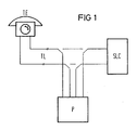
- FIG. 1 shows a subscriber terminal TE which is connected to a subscriber line circuit SLC via a subscriber line TL.
- a test device P has access via relays Re1 and Re2 to the subscriber line TL and to the subscriber line circuit SLC.
- the subscriber terminal TE is connected to the high-voltage part SLIC-H of a subscriber line circuit via a subscriber line TL.
- Line sensors S1 and S2 which serve to determine the subscriber line loop state, are indicated as essential parts of this high-voltage part.
- a cross-current signal is obtained via the resistors R1 to R4 and a differential amplifier VD1, which serves as a transmission signal.
- Received signals arriving from the opposite direction are amplified via line drivers T1 and T2 and given to the wires of the subscriber line.
- the high-voltage part also shows resistors R5 to R8, which are connected between the wires of the subscriber line and at the Connection points voltages are taken, which are fed to the inputs of a differential amplifier VD2 for obtaining a signal corresponding to the longitudinal current.
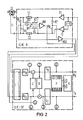
- FIG. 2 also shows, as a further component of the subscriber line circuit, a signal processor module SLIC-SP in a symbolic representation.
- the components of the signal processor module connected to the reception branch Rx or the transmission branch Tx of this module or inserted into these branches are to be understood as function blocks.
- devices for analog-to-digital conversion A / D or for digital-to-analog conversion D / A a negative feedback designated Z, which is used to adjust the 2-wire impedance
- a coupling designated B between the receiving branch Rx and via an adder on the transmission branch Tx, which is used for the 2-wire / 4-wire conversion
- blocks designated with GR and GT which serve for the gain setting in the corresponding branches Rx and Tx
- the actual control part P in which a digital interface is also shown.
- a correlation part labeled K is shown.
- Access points to which the signal processor has access via the digital interface mentioned are designated by numbers 2 to 5 on the receiving branch and on the transmitting branch or on the output of the differential amplifier VD2, which is why these numbers are also indicated in block P.
- a pair is selected from the voltages that occur at the points indicated during operation of the subscriber line circuit and subjected to the formation of a correlation product, from which a specific transmission property is then determined in each case.
- the table below shows the various possible combinations or different transmission properties to be checked.
- the reaction to separately fed signals which are fed back via a test loop L can also take place in their passive operation.
Landscapes
- Engineering & Computer Science (AREA)
- Signal Processing (AREA)
- Computer Networks & Wireless Communication (AREA)
- Monitoring And Testing Of Exchanges (AREA)
- Monitoring And Testing Of Transmission In General (AREA)
- Interface Circuits In Exchanges (AREA)
Abstract
Description
- Die Erfindung betrifft ein Verfahren zum Überprüfen von Übertragungseigenschaften einer Teilnehmeranschlußschaltung samt angeschlossener Teilnehmeranschlußleitung und daran angeschlossenem Teilnehmerendgerät eines digitalen Zeitmultiplex-Fernmeldesystems, wobei die Teilnehmeranschlußschaltung aus einem Hochvoltbaustein, der in erster Linie Leitungstreiber sowie Elemente zur Teilnehmerleitungszustandsindikation enthält und aus einem Signalprozessorbaustein besteht, in dem unter anderem die Analog-Digital-Wandlung und Digital-Analog-Wandlung, die Realisierung der 2-Draht-4-Draht-Wandlung, die Einstellung der 2-Drahtimpedanz, sowie die Sende- und Empfangssignalverstärkung erfolgt.
- Bisher wurden solche Prüfungen mit einem gesonderten Prüfgerät durchgeführt, das über vorgeleistete Relais Zugriff zu bestimmten Schaltungspunkten der Teilnehmeranschlußschaltung oder der Teilnehmeranschlußleitung hatte.
- Die Aufgabe der Erfindung besteht darin, ein Verfahren zum Überprüfen von Übertragungseigenschaften einer Teilnehmeranschlußschaltung, bei der die eingangs genannten Voraussetzungen gegeben sind, anzugeben, bei dessen Durchführung auf einen solchen Testzugriff über Relais verzichtet werden kann.
- Erfindungsgemäß wird die Aufgabe dadurch gelöst, daß über eine digitale Schnittstelle auf verschiedene Stellen des Empfangszweiges und des Sendezweiges des Ssignalprozessorbausteins zugegriffen wird und aus im Betrieb der Teilnehmeranschlußschaltung oder aufgrund gesondert eingespeister und reflektierter Signale an diesen Stellen auftretenden Spannungen in unterschiedlichen Kombinationen jeweils zweier solcher Spannungen ein Korrelationsprodukt gebildet wird, durch dessen Auswertung jeweils eine Angabe über eine bestimmte übertragungstechnische Eigenschaft erhalten wird.
- Gemäß weiterer Ausgestaltung der Erfindung erfolgt auch ein Zugriff und eine Korrelationsverarbeitung auf das im Hochvoltteil erhaltene Ergebnis der Längsstromauswertung.
- Nachstehend wird die Erfindung anhand eines Ausführungsbeispieles unter Bezugnahme auf eine Zeichnung näher erläutert.
- In der Zeichnung zeigen:
- FIG 1 in schematischer Darstellung den bisher praktizierten Testzugriff über Relais,
- FIG 2 eine in Hochvoltteil und Signalprozessorbaustein gegliederte Teilnehmeranschlußschaltung mit den zur Durchführung des erfindungsgemäßen Verfahrens erforderlichen Eigenschaften.
- In der FIG 1 ist ein Teilnehmerendgerät TE gezeigt, das über eine Teilnehmeranschlußleitung TL an eine Teilnehmeranschlußschaltung SLC angeschlossen ist. Eine Testeinrichtung P, auf deren Eigenschaften im einzelnen nicht eingegangen wird, hat Zugriff über Relais Re1 und Re2 auf die Teilnehmeranschlußleitung TL und auf die Teilnehmeranschlußschaltung SLC.
- Gemäß FIG 2 ist das Teilnehmerendgerät TE über eine Teilnehmeranschlußleitung TL an den Hochvoltteil SLIC-H einer Teilnehmeranschlußschaltung angeschlossen. Als wesentliche Teile dieses Hochvoltteils sind Leitungssensoren S1 und S2 angedeutet, die der Ermittlung des Teilnehmerleitungsschleifenzustandes dienen. Über die Widerstände R1 bis R4 und einen Differenzverstärker VD1 wird ein Querstromsignal gewonnen, das als Sendesignal dient. Aus der Gegenrichtung ankommende Empfangssignale werden über Leitungstreiber T1 und T2 verstärkt und an die Adern der Teilnehmeranschlußleitung gegeben. Der Hochvoltteil zeigt außerdem Widerstände R5 bis R8, die zwischen den Adern der Teilnehmeranschlußleitung angeschlossen sind und an deren Verbindungspunkte Spannungen abgenommen werden, die den Eingängen eines Differenzverstärkers VD2 zur Gewinnung eines dem Längsstrom entsprechenden Signals zugeführt werden.
- Die FIG 2 zeigt ferner als weiteren Bestandteil der Teilnehmeranschlußschaltung in symbolischer Darstellung einen Signalprozessorbaustein SLIC-SP. Die an den Empfangszweig Rx bzw. den Sendezweig Tx dieses Bausteins angeschlossene bzw. in diese Zweige eingefügten Bestandteile des Signalprozessorbausteins sind als Funktionsblöcke zu verstehen. Im einzelnen sind Einrichtungen zur Analog-Digital-Wandlung A/D bzw. zur Digital-Analog-Wandlung D/A, eine mit Z bezeichnete Gegenkopplung, die zur Einstellung der 2-Drahtimpedanz dient, eine mit B bezeichnete Kopplung, die zwischen dem Empfangszweig Rx und über ein Addierglied am Sendezweig Tx liegt, und die zur 2-Draht/4-Draht-Wandlung dient, ferner mit GR und GT bezeichnete Blöcke, die der Verstärkungseinstellung in den entsprechenden Zweigen Rx und Tx dienen, sowie der eigentliche Steuerteil P, in dem auch eine digitale Schnittstelle realisiert ist, gezeigt. Schließlich ist noch ein mit K bezeichneter Korrelationsteil dargestellt.
- Durch Ziffern 2 bis 5 am Empfangszweig und am Sendezweig bzw. am herangeführten Ausgang des Differenzverstärkers VD2 sind Zugriffspunkte bezeichnet, zu denen der Signalprozessor über die erwähnte digitale Schnittstelle Zugriff hat, weswegen auch im Block P diese Ziffern angegeben sind.
- Erfindungsgemäß wird aus den Spannungen, die im Betrieb der Teilnehmeranschlußschaltung an den bezeichneten Punkten auftreten, jeweils ein Paar ausgewählt und der Bildung eines Korrelationsproduktes unterworfen, aus dem dann jeweils eine bestimmte Übertragungseigenschaft ermittelt wird. Die nachstehende Tabelle zeigt dabei die verschiedenen Kombinationsmöglichkeiten bzw. verschiedene zu prüfende Übertragungseigenschaften.

- Anstelle einer Prüfung im aktiven Betrieb der Teilnehmeranschlußschaltung kann auch in deren passivem Betrieb die Reaktion auf gesondert eingespeiste und über eine Testschleife L zurückgeführte Signale erfolgen.
Claims (2)
- Verfahren zum Überprüfen von Übertragungseigenschaften einer Teilnehmeranschlußschaltung samt angeschlossener Teilnehmeranschlußleitung und daran angeschlossenem Teilnehmerendgerät eines digitalen Zeitmultiplex-Fernsprechsystems, wobei die Teilnehmeranschlußschaltung aus einem Hochvoltbaustein, der in erster Linie die Leitungstreiber sowie Elemente zur Teilnehmerleitungszustandsindikation enthält und aus einem Signalprozessorbaustein besteht, in dem unter anderem die Analog-Digitial-Wandlung und Digital-Analog-Wandlung mit zugehöriger Filterung, die Realisierung der 2-Draht-4-Draht-Wandlung, die Einstellung der 2-Drahtimpedanz sowie die Sende-und die Empfangssignalverstärkung erfolgt,
dadurch gekennzeichnet,
daß über eine digitale Schnittstelle auf verschiedene Stellen (0 bis 4, 6 ) des Empfangszweiges (Rx) und des Sendezweiges (Tx) des Signalprozessorbausteins zugegriffen wird und aus im Betrieb der Teilnehmeranschlußschaltung oder aufgrund gesondert eingespeister und reflektierter Signale an diesen Stellen auftretende Spannungen in unterschiedlichen Kombinationen jeweils zweier Spannungswerte ein Korrelationsprodukt gebildet wird, durch dessen Auswertung eine Angabe über eine bestimmte übertragungstechnische Eigenschaft erhalten wird. - Verfahren nach Anspruch 1,
dadurch gekennzeichnet,
daß zusätzlich ein Zugriff auf das im Hochvoltteil (SLIC-H) erhaltene Ergebnis der Längsstromauswertung und eine entsprechende Korrelationsverarbeitung erfolgt.
Applications Claiming Priority (2)
| Application Number | Priority Date | Filing Date | Title |
|---|---|---|---|
| DE4011985 | 1990-04-12 | ||
| DE4011985 | 1990-04-12 |
Publications (3)
| Publication Number | Publication Date |
|---|---|
| EP0451759A2 true EP0451759A2 (de) | 1991-10-16 |
| EP0451759A3 EP0451759A3 (en) | 1993-06-16 |
| EP0451759B1 EP0451759B1 (de) | 1996-11-20 |
Family
ID=6404357
Family Applications (1)
| Application Number | Title | Priority Date | Filing Date |
|---|---|---|---|
| EP91105532A Expired - Lifetime EP0451759B1 (de) | 1990-04-12 | 1991-04-08 | Verfahren zum Überprüfen von Übertragungseigenschaften einer Teilnehmeranschlussschaltung |
Country Status (6)
| Country | Link |
|---|---|
| US (1) | US5202882A (de) |
| EP (1) | EP0451759B1 (de) |
| AT (1) | ATE145507T1 (de) |
| DE (1) | DE59108356D1 (de) |
| ES (1) | ES2095265T3 (de) |
| GR (1) | GR3021752T3 (de) |
Cited By (6)
| Publication number | Priority date | Publication date | Assignee | Title |
|---|---|---|---|---|
| EP0553436A3 (en) * | 1991-12-13 | 1993-10-27 | Kommunikations Elektronik | Method for testing the operation of transmission links for telecommunication signals |
| EP0613279A3 (en) * | 1993-02-04 | 1995-09-13 | Alcatel Str Ag | Method for data extraction on a two-wire telephone line with digital data traffic and device for execution of this method. |
| DE19650320A1 (de) * | 1996-12-04 | 1998-06-25 | Siemens Ag | Elektronische Teilnehmeranschlußschaltung einer digitalen Fernmeldevermittlungsstelle, die zur Durchführung von Prüffunktionen ausgestattet ist |
| DE19802825C1 (de) * | 1998-01-26 | 1999-08-12 | Siemens Ag | Verfahren zur schnellen Prüfung der Funktionsfähigkeit eines Teilnehmersatzes |
| RU2162278C2 (ru) * | 1996-09-27 | 2001-01-20 | Сименс АГ | Схема абонентского ввода для подключения аналоговой абонентской линии к цифровой телефонной станции с временным уплотнением каналов |
| US7286952B1 (en) | 1998-09-30 | 2007-10-23 | Siemens Aktiengesellschaft | Method for testing subscriber access lines |
Families Citing this family (8)
| Publication number | Priority date | Publication date | Assignee | Title |
|---|---|---|---|---|
| IT1252125B (it) * | 1991-10-23 | 1995-06-05 | Sgs Thomson Microelectronics | Metodo e dispositivo circuitale per misurare in condizioni di esercizio parametri operativi di un circuito di interfaccia e di una linea telefonica d'utente ad esse collegata |
| US5436953A (en) * | 1993-07-02 | 1995-07-25 | Northern Telecom Limited | Digital longitudinal balance measurement |
| US5956386A (en) * | 1997-06-20 | 1999-09-21 | Advanced Micro Devices, Inc. | Telephone subscriber line diagnostics system and method |
| DE19802826C2 (de) * | 1998-01-26 | 1999-11-18 | Siemens Ag | Verfahren zum Abgleich von um Störgrößen verfälschte Stromwerte eines Teilnehmersatzes |
| EP1592214B1 (de) | 2004-04-28 | 2012-12-26 | Lantiq Deutschland GmbH | Anordnung und Verfahren zur Messung von elektrischen Eigenschaften von Kommunikationsleitungen, die an einer Leitungskarte angeschlossen sind |
| US9225825B2 (en) * | 2006-07-18 | 2015-12-29 | Lantiq Deutschland Gmbh | Method and apparatus for line testing |
| US8102970B2 (en) * | 2006-07-18 | 2012-01-24 | Lantiq Deutschland Gmbh | Method and apparatus for line testing |
| US9025733B2 (en) * | 2006-07-18 | 2015-05-05 | Lantiq Deutschland Gmbh | Method and apparatus for line testing |
Family Cites Families (7)
| Publication number | Priority date | Publication date | Assignee | Title |
|---|---|---|---|---|
| US4376450A (en) * | 1978-07-03 | 1983-03-15 | Scovill Manufacturing Co. - Scovill, Inc. | Valve position monitor and control system |
| HU187198B (en) * | 1982-12-14 | 1985-11-28 | Bhg Hiradastech Vallalat | Circuit arrangemenet for the supervison of the telephon circuits |
| US4611320A (en) * | 1984-05-21 | 1986-09-09 | Siemens Corporate Research And Support, Inc. | Programmable testing analyzer |
| ATA300485A (de) * | 1985-10-17 | 1991-05-15 | Siemens Ag Oesterreich | Einrichtung zur ueberwachung einer schaltstelle fuer die zeitmultiplexe zusammenfuegung mehrerer nachrichtenkanaele fuer digitalsignale, insbesondere fuer pulscodemodulierte signale |
| GB2201535B (en) * | 1987-02-25 | 1990-11-28 | Motorola Inc | Cmos analog multiplying circuit |
| EP0286835B1 (de) * | 1987-04-14 | 1992-01-15 | Siemens Aktiengesellschaft | Verfahren und Schaltungsanordnung zur Einstellung der Teilnehmerleitungs-Nachbildungsimpedanzen von programmierbaren Gabelschaltung |
| GB2224846A (en) * | 1988-11-14 | 1990-05-16 | Philips Electronic Associated | Temperature sensing circuit |
-
1991
- 1991-04-08 AT AT91105532T patent/ATE145507T1/de not_active IP Right Cessation
- 1991-04-08 ES ES91105532T patent/ES2095265T3/es not_active Expired - Lifetime
- 1991-04-08 EP EP91105532A patent/EP0451759B1/de not_active Expired - Lifetime
- 1991-04-08 DE DE59108356T patent/DE59108356D1/de not_active Expired - Fee Related
- 1991-04-11 US US07/683,689 patent/US5202882A/en not_active Expired - Fee Related
-
1996
- 1996-11-21 GR GR960402898T patent/GR3021752T3/el unknown
Cited By (9)
| Publication number | Priority date | Publication date | Assignee | Title |
|---|---|---|---|---|
| EP0553436A3 (en) * | 1991-12-13 | 1993-10-27 | Kommunikations Elektronik | Method for testing the operation of transmission links for telecommunication signals |
| EP0613279A3 (en) * | 1993-02-04 | 1995-09-13 | Alcatel Str Ag | Method for data extraction on a two-wire telephone line with digital data traffic and device for execution of this method. |
| RU2162278C2 (ru) * | 1996-09-27 | 2001-01-20 | Сименс АГ | Схема абонентского ввода для подключения аналоговой абонентской линии к цифровой телефонной станции с временным уплотнением каналов |
| EP0835014A3 (de) * | 1996-09-27 | 2004-01-14 | Siemens Aktiengesellschaft | Teilnehmeranschlussschaltung für den Anschluss einer analogen Teilnehmerleitung an eine digitale Zeitmultiplex-Fernsprechvermittlungsstelle |
| DE19650320A1 (de) * | 1996-12-04 | 1998-06-25 | Siemens Ag | Elektronische Teilnehmeranschlußschaltung einer digitalen Fernmeldevermittlungsstelle, die zur Durchführung von Prüffunktionen ausgestattet ist |
| DE19802825C1 (de) * | 1998-01-26 | 1999-08-12 | Siemens Ag | Verfahren zur schnellen Prüfung der Funktionsfähigkeit eines Teilnehmersatzes |
| WO1999038304A3 (de) * | 1998-01-26 | 1999-10-07 | Siemens Ag | Verfahren zur schnellen prüfung der funktionsfähigkeit eines teilnehmersatzes |
| US6490342B1 (en) | 1998-01-26 | 2002-12-03 | Siemens Aktiengesellschaft | Method for quickly testing the operability of a subscriber circuit |
| US7286952B1 (en) | 1998-09-30 | 2007-10-23 | Siemens Aktiengesellschaft | Method for testing subscriber access lines |
Also Published As
| Publication number | Publication date |
|---|---|
| US5202882A (en) | 1993-04-13 |
| ES2095265T3 (es) | 1997-02-16 |
| GR3021752T3 (en) | 1997-02-28 |
| EP0451759A3 (en) | 1993-06-16 |
| EP0451759B1 (de) | 1996-11-20 |
| DE59108356D1 (de) | 1997-01-02 |
| ATE145507T1 (de) | 1996-12-15 |
Similar Documents
| Publication | Publication Date | Title |
|---|---|---|
| EP0451759B1 (de) | Verfahren zum Überprüfen von Übertragungseigenschaften einer Teilnehmeranschlussschaltung | |
| DE3821772B4 (de) | Optische Zweiwege-Signalübertragungsvorrichtung mit einer Einrichtung zur Fehlerlokalisierung | |
| EP0480323A2 (de) | Leitungseinrichtung zur Kompensation von Nebensprechen | |
| DE3990712C2 (de) | Schnittstelleneinheit | |
| DE2801469C2 (de) | Senderempfänger eines Vollduplex-Übertragungssystems | |
| DE69533542T2 (de) | Funktelefon-basisstation mit einer überwachungseinrichtung | |
| DE3115892A1 (de) | "transformatorlose zweidraht-/vierdrahtgabelschaltung" | |
| DE2736136B2 (de) | Schaltungsanordnung zur Fehlersignalkompensation in Zweidraht-Vierdraht-Gabelschaltungen | |
| DE68922946T2 (de) | Endschaltung in einer Batteriespeisungsschaltung eines elektronischen Vermittlungssystems. | |
| EP0016472B1 (de) | Anordnung mit einer Gabelschaltung für den Zweidraht-Vierdraht-Übergang in PCM-Zeitmultiplexsystemen | |
| DE4308783C1 (de) | Schaltungsanordnung zur Übertragung nachrichtentechnischer Signale | |
| EP0040785B1 (de) | Übertragerfreie Gabelschaltung | |
| EP1166513B1 (de) | Verfahren und vorrichtung zum übertragen eines sendesignals über eine zweiadrige leitung | |
| EP0209716B1 (de) | Schaltungsanordnung zur Unterdrückung von Störsignalen auf dem Empfangszweig einer unter Verwendung von elektronischen Bauelementen aufgebauten und damit ohne Sprachübertrager realisierten Teilnehmeranschlussschaltung | |
| DE3715594C2 (de) | Anordnung zum Anschluß von Ausgangs- und Eingangsstufen einer Sende/Empfangseinrichtung | |
| EP0286835B1 (de) | Verfahren und Schaltungsanordnung zur Einstellung der Teilnehmerleitungs-Nachbildungsimpedanzen von programmierbaren Gabelschaltung | |
| DE826600C (de) | Pruefanordnung fuer Fernmelde-Zweiwegsysteme | |
| EP0477660B1 (de) | Schaltungsanordnung zum Empfang von Informationen, die über Starkstromleitungen übertragen werden | |
| DE2812198C2 (de) | Zeitmultiplex-Fernmeldesystem zum Verbinden von Zweidrahtleitungskreisen | |
| DE2725063C2 (de) | System zur Übertragung eines Dienstkanals | |
| DE802395C (de) | Schaltungsanordnung fuer die Verbindung von Zweidraht- und Vierdrahtleitungen in Vermittlungsstellen | |
| DE1811848C3 (de) | Anordnung zur Herstellung eines von einer beliebigen Stelle einer Zweidrahtleitung aus geführten Gespräches | |
| DE10361039B4 (de) | Kommunikationsvorrichtung für Daten und Sprache | |
| DE1178478B (de) | Zeitmultiplexuebertragungsanlage | |
| EP0480322A2 (de) | Schaltungsanordnung zur Kompensation von Impulsstörungen |
Legal Events
| Date | Code | Title | Description |
|---|---|---|---|
| PUAI | Public reference made under article 153(3) epc to a published international application that has entered the european phase |
Free format text: ORIGINAL CODE: 0009012 |
|
| AK | Designated contracting states |
Kind code of ref document: A2 Designated state(s): AT BE CH DE ES FR GB GR IT LI LU NL SE |
|
| PUAL | Search report despatched |
Free format text: ORIGINAL CODE: 0009013 |
|
| AK | Designated contracting states |
Kind code of ref document: A3 Designated state(s): AT BE CH DE ES FR GB GR IT LI LU NL SE |
|
| 17P | Request for examination filed |
Effective date: 19930701 |
|
| 17Q | First examination report despatched |
Effective date: 19950502 |
|
| GRAG | Despatch of communication of intention to grant |
Free format text: ORIGINAL CODE: EPIDOS AGRA |
|
| GRAH | Despatch of communication of intention to grant a patent |
Free format text: ORIGINAL CODE: EPIDOS IGRA |
|
| GRAH | Despatch of communication of intention to grant a patent |
Free format text: ORIGINAL CODE: EPIDOS IGRA |
|
| GRAA | (expected) grant |
Free format text: ORIGINAL CODE: 0009210 |
|
| AK | Designated contracting states |
Kind code of ref document: B1 Designated state(s): AT BE CH DE ES FR GB GR IT LI LU NL SE |
|
| REF | Corresponds to: |
Ref document number: 145507 Country of ref document: AT Date of ref document: 19961215 Kind code of ref document: T |
|
| REG | Reference to a national code |
Ref country code: CH Ref legal event code: NV Representative=s name: SIEMENS SCHWEIZ AG |
|
| REF | Corresponds to: |
Ref document number: 59108356 Country of ref document: DE Date of ref document: 19970102 |
|
| ET | Fr: translation filed | ||
| REG | Reference to a national code |
Ref country code: GR Ref legal event code: FG4A Free format text: 3021752 |
|
| ITF | It: translation for a ep patent filed | ||
| REG | Reference to a national code |
Ref country code: ES Ref legal event code: FG2A Ref document number: 2095265 Country of ref document: ES Kind code of ref document: T3 |
|
| GBT | Gb: translation of ep patent filed (gb section 77(6)(a)/1977) |
Effective date: 19970123 |
|
| PLBE | No opposition filed within time limit |
Free format text: ORIGINAL CODE: 0009261 |
|
| STAA | Information on the status of an ep patent application or granted ep patent |
Free format text: STATUS: NO OPPOSITION FILED WITHIN TIME LIMIT |
|
| 26N | No opposition filed | ||
| PGFP | Annual fee paid to national office [announced via postgrant information from national office to epo] |
Ref country code: CH Payment date: 19980709 Year of fee payment: 8 |
|
| PGFP | Annual fee paid to national office [announced via postgrant information from national office to epo] |
Ref country code: GR Payment date: 19990323 Year of fee payment: 9 |
|
| PGFP | Annual fee paid to national office [announced via postgrant information from national office to epo] |
Ref country code: AT Payment date: 19990331 Year of fee payment: 9 |
|
| PGFP | Annual fee paid to national office [announced via postgrant information from national office to epo] |
Ref country code: GB Payment date: 19990413 Year of fee payment: 9 |
|
| PGFP | Annual fee paid to national office [announced via postgrant information from national office to epo] |
Ref country code: SE Payment date: 19990414 Year of fee payment: 9 |
|
| PGFP | Annual fee paid to national office [announced via postgrant information from national office to epo] |
Ref country code: LU Payment date: 19990416 Year of fee payment: 9 |
|
| PGFP | Annual fee paid to national office [announced via postgrant information from national office to epo] |
Ref country code: BE Payment date: 19990419 Year of fee payment: 9 |
|
| PGFP | Annual fee paid to national office [announced via postgrant information from national office to epo] |
Ref country code: ES Payment date: 19990420 Year of fee payment: 9 |
|
| PGFP | Annual fee paid to national office [announced via postgrant information from national office to epo] |
Ref country code: FR Payment date: 19990422 Year of fee payment: 9 |
|
| PGFP | Annual fee paid to national office [announced via postgrant information from national office to epo] |
Ref country code: NL Payment date: 19990427 Year of fee payment: 9 |
|
| PG25 | Lapsed in a contracting state [announced via postgrant information from national office to epo] |
Ref country code: LI Free format text: LAPSE BECAUSE OF NON-PAYMENT OF DUE FEES Effective date: 19990430 Ref country code: CH Free format text: LAPSE BECAUSE OF NON-PAYMENT OF DUE FEES Effective date: 19990430 |
|
| REG | Reference to a national code |
Ref country code: CH Ref legal event code: PL |
|
| PG25 | Lapsed in a contracting state [announced via postgrant information from national office to epo] |
Ref country code: LU Free format text: LAPSE BECAUSE OF NON-PAYMENT OF DUE FEES Effective date: 20000408 Ref country code: AT Free format text: LAPSE BECAUSE OF NON-PAYMENT OF DUE FEES Effective date: 20000408 Ref country code: GB Free format text: LAPSE BECAUSE OF NON-PAYMENT OF DUE FEES Effective date: 20000408 |
|
| PG25 | Lapsed in a contracting state [announced via postgrant information from national office to epo] |
Ref country code: SE Free format text: LAPSE BECAUSE OF NON-PAYMENT OF DUE FEES Effective date: 20000409 |
|
| PG25 | Lapsed in a contracting state [announced via postgrant information from national office to epo] |
Ref country code: ES Free format text: THE PATENT HAS BEEN ANNULLED BY A DECISION OF A NATIONAL AUTHORITY Effective date: 20000410 |
|
| PG25 | Lapsed in a contracting state [announced via postgrant information from national office to epo] |
Ref country code: GR Free format text: LAPSE BECAUSE OF NON-PAYMENT OF DUE FEES Effective date: 20000430 Ref country code: BE Free format text: LAPSE BECAUSE OF NON-PAYMENT OF DUE FEES Effective date: 20000430 |
|
| BERE | Be: lapsed |
Owner name: SIEMENS A.G. Effective date: 20000430 |
|
| PG25 | Lapsed in a contracting state [announced via postgrant information from national office to epo] |
Ref country code: NL Free format text: LAPSE BECAUSE OF NON-PAYMENT OF DUE FEES Effective date: 20001101 |
|
| GBPC | Gb: european patent ceased through non-payment of renewal fee |
Effective date: 20000408 |
|
| EUG | Se: european patent has lapsed |
Ref document number: 91105532.5 |
|
| PG25 | Lapsed in a contracting state [announced via postgrant information from national office to epo] |
Ref country code: FR Free format text: LAPSE BECAUSE OF NON-PAYMENT OF DUE FEES Effective date: 20001229 |
|
| NLV4 | Nl: lapsed or anulled due to non-payment of the annual fee |
Effective date: 20001101 |
|
| REG | Reference to a national code |
Ref country code: FR Ref legal event code: ST |
|
| REG | Reference to a national code |
Ref country code: ES Ref legal event code: FD2A Effective date: 20020304 |
|
| PG25 | Lapsed in a contracting state [announced via postgrant information from national office to epo] |
Ref country code: IT Free format text: LAPSE BECAUSE OF NON-PAYMENT OF DUE FEES;WARNING: LAPSES OF ITALIAN PATENTS WITH EFFECTIVE DATE BEFORE 2007 MAY HAVE OCCURRED AT ANY TIME BEFORE 2007. THE CORRECT EFFECTIVE DATE MAY BE DIFFERENT FROM THE ONE RECORDED. Effective date: 20050408 |
|
| PGFP | Annual fee paid to national office [announced via postgrant information from national office to epo] |
Ref country code: DE Payment date: 20080418 Year of fee payment: 18 |
|
| PG25 | Lapsed in a contracting state [announced via postgrant information from national office to epo] |
Ref country code: DE Free format text: LAPSE BECAUSE OF NON-PAYMENT OF DUE FEES Effective date: 20091103 |