EP0451796B1 - Sprachdetektor mit vermindertem Einfluss von Engangssignalpegel und Rauschen - Google Patents
Sprachdetektor mit vermindertem Einfluss von Engangssignalpegel und Rauschen Download PDFInfo
- Publication number
- EP0451796B1 EP0451796B1 EP91105621A EP91105621A EP0451796B1 EP 0451796 B1 EP0451796 B1 EP 0451796B1 EP 91105621 A EP91105621 A EP 91105621A EP 91105621 A EP91105621 A EP 91105621A EP 0451796 B1 EP0451796 B1 EP 0451796B1
- Authority
- EP
- European Patent Office
- Prior art keywords
- noise
- speech
- parameter
- input frame
- parameters
- Prior art date
- Legal status (The legal status is an assumption and is not a legal conclusion. Google has not performed a legal analysis and makes no representation as to the accuracy of the status listed.)
- Expired - Lifetime
Links
- 238000001514 detection method Methods 0.000 title claims description 71
- 239000011159 matrix material Substances 0.000 claims description 21
- 230000005236 sound signal Effects 0.000 claims description 21
- 230000009466 transformation Effects 0.000 claims description 14
- 230000001131 transforming effect Effects 0.000 claims description 10
- 238000004364 calculation method Methods 0.000 description 47
- 238000010586 diagram Methods 0.000 description 17
- 238000010606 normalization Methods 0.000 description 9
- 238000010276 construction Methods 0.000 description 7
- 238000004891 communication Methods 0.000 description 2
- 238000012986 modification Methods 0.000 description 2
- 230000004048 modification Effects 0.000 description 2
- 238000005070 sampling Methods 0.000 description 2
- 238000001228 spectrum Methods 0.000 description 2
- 238000012549 training Methods 0.000 description 2
- 230000000694 effects Effects 0.000 description 1
- 238000000034 method Methods 0.000 description 1
- 230000000737 periodic effect Effects 0.000 description 1
- 238000009331 sowing Methods 0.000 description 1
- 230000003595 spectral effect Effects 0.000 description 1
- 238000012360 testing method Methods 0.000 description 1
- 238000012546 transfer Methods 0.000 description 1
Images





Classifications
-
- G—PHYSICS
- G10—MUSICAL INSTRUMENTS; ACOUSTICS
- G10L—SPEECH ANALYSIS TECHNIQUES OR SPEECH SYNTHESIS; SPEECH RECOGNITION; SPEECH OR VOICE PROCESSING TECHNIQUES; SPEECH OR AUDIO CODING OR DECODING
- G10L25/00—Speech or voice analysis techniques not restricted to a single one of groups G10L15/00 - G10L21/00
- G10L25/78—Detection of presence or absence of voice signals
Definitions
- the present invention relates to a speech detection apparatus for detecting speech segments in audio signals appearing in such a field as the ATM (asynchronous transfer mode) communication, DSI (digital speech interpolation), packet communication, and speech recognition.
- ATM asynchronous transfer mode
- DSI digital speech interpolation
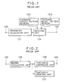
- FIG. 1 An example of a conventional speech detection apparatus for detecting speech segments in audio signals is shown in Fig. 1.
- This speech detection apparatus of Fig. 1 comprises: an input terminal 100 for inputting the audio signals; a parameter calculation unit 101 for acoustically analyzing the input audio signals frame by frame to extract parameters such as energy, zero-crossing rates, auto-correlation coefficients, and spectrum; a standard speech pattern memory 102 for storing standard speech patterns prepared in advance; a standard noise pattern memory 103 for storing standard noise patterns prepared in advance; a matching unit 104 for Judging whether the input frame is speech or noise by comparing parameters with each of the standard patterns; and an output terminal 105 for outputting a signal which indicates the input frame as speech or noise according to the judgement made by the matching unit 104.
- the audio signals from the input terminal 100 are acoustically analyzed by the parameter calculation unit 101, and then parameters such as energy, zero-crossing rates, auto-correlation coefficients, and spectrum are extracted frame by frame.
- the matching unit 104 decides the input frame as speech or noise.
- the decision algorithm such as the Bayer Linear Classifier can be used in making this decision.
- the output terminal 105 then outputs the result of the decision made by the matching unit 104.
- FIG. 2 Another example of a conventional speech detection apparatus for detecting speech segments in audio signals is shown in Fig. 2.
- This speech detection apparatus of Fig. 2 is one which uses only the energy as the parameter, and comprises: an input terminal 100 for inputting the audio signals; an energy calculation unit 106 for calculating an energy P(n) of each input frame; a threshold comparison unit 108 for judging whether the input frame is speech or noise by comparing the calculated energy P(n) of the input frame with a threshold T(n); a threshold updating unit 107 for updating the threshold T(n) to be used by the threshold comparison unit 108; and an output terminal 105 for outputting a signal which indicates the input frame as speech or noise according to the Judgement made by the threshold comparison unit 108.
- the energy P(n) is calculated by the energy calculation unit 106.
- the input frame is recognized as a speech segment if the energy P(n) is greater than the current threshold T(n). Otherwise,.the input frame is recognized as a noise segment.
- the result of this recognition obtained by the threshold comparison unit 108 is then outputted from the output terminal 105.
- such a conventional speech detection apparatus has the following problems. Namely, under the heavy background noise or the low speech energy environment, the parameters of speech segments are affected by the background noise. In particular, some consonants are severely affected because their energies are lowerer than the energy of the background noise. Thus, in such a circumstance, it is difficult to judge whether the input frame is speech or noise and the discrimination errors occur frequently.
- EP-0 335 521 A1 discloses an apparatus for voice activity detection, which comprises means for receiving an input signal, means for estimating the noise signal component of the input signal, means for continually forming a measure M of the spectral similarity between a portion of the input signal and the noise signal, and means for comparing a parameter derived from the measure M with a threshold value T to produce an output to indicate the presence or absence of speech, depending upon whether or not that value is exceeded.
- a buffer is used for storing coefficients derived from a microphone input in a period identified as being a noise-only period, where these stored coefficient are then used to derive said measure M.
- Fig. 1 is a schematic block diagram of an example of a conventional speech detection apparatus.
- Fig. 2 is a schematic block diagram of another example of a conventional speech detection apparatus.
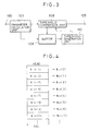
- Fig. 3 is a schematic block diagram of the first embodiment of a speech detection apparatus according to the present invention.
- Fig. 4 is a diagrammatic illustration of a buffer in the speech detection apparatus of Fig. 3 for showing an order of its contents.
- Fig. 5 is a block diagram of a threshold generation unit of the speech detection apparatus of Fig. 3.
- Fig. 6 is a schematic block diagram of the second embodiment of a speech detection apparatus according to the present invention.
- Fig. 7 is a block diagram of a parameter transformation unit of the speech detection apparatus of Fig. 6.
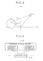
- Fig. 8 is a graph sowing a relationships among a transformed parameter, a parameter, a mean vector, and a set of parameters of the input frames which are estimated as noise in the speech detection apparatus of Fig. 6.
- Fig. 9 is a block diagram of a Judging unit of the speech detection apparatus of Fig. 6.
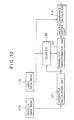
- Fig. 10 is a block diagram of a modified configuration for the speech detection apparatus of Fig. 6 in a case of obtaining standard patterns.
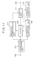
- Fig. 11 is a schematic block diagram of the third embodiment of a speech detection apparatus according to the present invention.
- Fig. 12 is a block diagram of a modified configuration for the speech detection apparatus-of Fig. 11 in a case of obtaining standard patterns.
- Fig. 13 is a graph of a detection rate versus an input signal level for the speech detection apparatuses of Fig. 3 and Fig. 11, and a conventional speech detection apparatus.
- Fig. 14 is a graph of a detection rate versus an S/N ratio for the speech detection apparatuses of Fig. 3 and Fig. 11, and a conventional speech detection apparatus.
- Fig. 15 is a schematic block diagram of the fourth embodiment of a speech detection apparatus according to the present invention.
- Fig. 16 is a block diagram of a noise segment pre-estimation unit of the speech detection apparatus of Fig. 15.
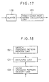
- Fig. 17 is a block diagram of a noise standard pattern construction unit of the speech detection apparatus of Fig. 15.
- Fig. 18 is a block diagram of a Judging unit of the speech detection apparatus of Fig. 15.
- Fig. 19 is a block diagram of a modified configuration for the speech detection apparatus of Fig. 15 in a case of obtaining standard patterns.
- Fig. 20 is a schematic block diagram of the fifth embodiment of a speech detection apparatus according to the present invention.
- Fig. 21 is a block diagram of a transformed parameter calculation unit of the speech detection apparatus of Fig. 20.
- Fig. 3 the first embodiment of a speech detection apparatus according to the present invention will be described in detail.
- This speech detection apparatus of Fig. 3 comprises: an input terminal 100 for inputting the audio signals; a parameter calculation unit 101 for acoustically analyzing each input frame to extract parameter of the input frame; a threshold comparison unit 108 for judging whether the input frame is speech or noise by comparing the calculated parameter of each input frame with a threshold; a buffer 109 for storing the calculated parameters of those input frames which are discriminated as the noise segments by the threshold comparison unit 108; a threshold generation unit 110 for generating the threshold to be used by the threshold comparison unit 108 according to the parameters stored in the buffer 109; and an output terminal 105 for outputting a signal which indicates the input frame as speech or noise according to the Judgement made by the threshold comparison unit 108.
- the audio signals from the input terminal 100 are acoustically analyzed by the parameter calculation unit 101, and then the parameter for each input frame is extracted frame by frame.
- the discrete-time signals are derived from continuous-time input signals by periodic sampling, where 160 samples constitute one frame.
- periodic sampling where 160 samples constitute one frame.
- the frame length and sampling frequency there is no need for the frame length and sampling frequency to be fixed.
- the parameter calculation unit 101 calculates energy, zero-crossing rates, auto-correlation coefficients, linear predictive coefficients, the PARCOR coefficients, LPC cepstrum, mel-cepstrum, etc. Some of them are used as components of a parameter vector X(n) of each n-th input frame.
- the parameter X(n) so obtained can be represented as a p-dimensional vector given by the following expression (9).
- X(n) (x 1 (n), x 2 (n), ⁇ , x p (n))
- the buffer 109 stores the calculated parameters of those input frames which are discriminated as the noise segments by the threshold comparison unit 108 in time sequential order as shown in Fig. 4, from a head of the buffer 109 toward a tail of the buffer 109, such that the newest parameter is at the head of the buffer 109 while the oldest parameter is at the tail of the buffer 109.
- the parameters stored in the buffer 109 are only a part of the parameters calculated by the parameter calculation unit 101 and therefore may not necessarily be continuous in time sequence.
- the threshold generation unit 110 has a detail configuration shown in Fig. 5 which comprises a normalization coefficient calculation unit 110a for calculating a mean and a standard deviation of the parameters of a part of the input frames stored in the buffer 109; and a threshold calculation unit 110b for calculating the threshold from the calculated mean and standard deviation.
- a set ⁇ (n) constitutes N parameters from the S-th frame of the buffer 109 toward the tail of the buffer 109.
- the set ⁇ (n) can be expressed as the following expression (10). ⁇ (n) : ⁇ X Ln (S), X Ln (S+1), ⁇ , X Ln (S+N-1) ⁇ where X Ln (i) is another expression of the parameters in the buffer 109 as shown in Fig. 4.
- the normalization coefficient calculation unit 110a calculates the mean m i and the standard deviation ⁇ i of each element of the parameters in the set ⁇ (n) according to the following equations (11) and (12).
- X Ln (j) ⁇ x Ln1 (j), x Ln2 (j), ⁇ , x Lnp (j) ⁇
- the mean m; and the standard deviation ⁇ i for each element of the parameters in the set ⁇ (n) may be given by the following equations (13) and (14).
- j satisfies the following condition (15): X(j) ⁇ ⁇ '(n) and j ⁇ n - S and takes a larger value in the buffer 109, and where ⁇ '(n) is a set of the parameters in the buffer 109.
- the threshold calculation unit 110b then calculates the threshold T(n) to be used by the threshold comparison unit 108 according to the following equation (16).
- T(n) ⁇ ⁇ m i + ⁇ ⁇ ⁇ i where ⁇ and ⁇ are arbitrary constants, and 1 ⁇ i ⁇ P.
- the threshold T(n) is taken to be a predetermined initial threshold T 0 ⁇ .
- the threshold comparison unit 108 then compares the parameter of each input frame calculated by the parameter calculation unit 101 with the threshold T(n) calculated by the threshold calculation unit 110b, and then judges whether the input frame is speech or noise.
- the parameter can be one-dimensional and positive in a case of using the energy or a zero-crossing rate as the parameter.
- the parameter X(n) is the energy of the input frame
- each input frame is judged as a speech segment under the following condition (17): X(n) ⁇ T(n)
- each input frame is judged as a noise segment under the following condition (18): X(n) ⁇ T(n)
- the conditions (17) and (18) may be interchanged when using any other type of the parameter.
- a signal which indicates the input frame as speech or noise is then outputted from the output terminal 105 according to the judgement made by the threshold comparison unit 108.
- Fig. 6 the second embodiment of a speech detection apparatus according to the present invention will be described in detail.
- This speech detection apparatus of Fig. 6 comprises: an input terminal 100 for inputting the audio signals; a parameter calculation unit 101 for acoustically analyzing each input frame to extract parameter; a parameter transformation unit 112 for transforming the parameter extracted by the parameter calculation unit 101 to obtain a transformed parameter for each input frame; a judging unit 111 for judging whether each input-frame is a speech segment or a noise segment according to the transformed parameter obtained by the parameter transformation unit 112; a buffer 109 for storing the calculated parameters of those input frames which are judged as the noise segments by the judging unit 111; a buffer control unit 113 for inputting the calculated parameters of those input frames which are Judged as the noise segments by the Judging unit 111 into the buffer 109; and an output terminal 105 for outputting a signal which indicates the input frame as speech or noise according to the judgement made by the judging unit 111.
- the audio signals from the input terminal 100 are acoustically analyzed by the parameter calculation unit 101, and then theparameter X (n) for each input frame is extracted frame by frame, as in the first embodiment described above.
- the parameter transformation unit 112 then transforms the extracted parameter X (n) into the transformed parameter Y (n) in which the difference between speech and noise is emphasized.
- the transformed parameter Y (n), corresponding to the parameter X (n) in a form of a p-dimensional vector, is an r-dimensional (r ⁇ p) vector represented by the following expression (19).
- Y(n) (y 1 (n), y 2 (n), ⁇ , y r (n))
- the parameter transformation unit 112 has a detail configuration shown in Fig. 7 which comprises a normalization coefficient calculation unit 110a for calculating a mean and a standard deviation of the parameters in the buffer 109; and a normalization unit 112a for calculating the transformed parameter using the calculated mean and standard deviation.
- the normalization coefficient calculation unit 110a calculates the mean m i and the standard deviation ⁇ i for each element in the parameters of a set ⁇ (n), where a set ⁇ (n) constitutes N parameters from the S-th frame of the buffer 109 toward the tail of the buffer 109, as in the first embodiment described above.
- the buffer control unit 113 inputs the calculated parameters of those input frames which are judged as the noise segments by the judging unit 111 into the buffer 109.
- the judging unit 111 for judging whether each input frame is a speech segment or noise segment has a detail configuration shown in Fig. 9 which comprises: a standard pattern memory lllb for memorizing M standard patterns for the speech segment and the noise segment; and a matching unit llla for judging whether the input frame is speech or not by comparing the distances between the transformed parameter obtained by the parameter transformation unit 112 with each of the standard patterns.
- D i (Y(n)) (Y(n) - ⁇ i ) t ⁇ i -1 (Y(n) - ⁇ i ) + ln
- the n-th input frame is judged as a speech segment when the class ⁇ i represents speech, or as a noise segment otherwise, where the suffix i makes the distance D i (Y) minimum.
- some classes represent speech and some classes represent noise.
- the standard patterns are obtained in advance by the apparatus as shown in Fig. 10, where the speech detection apparatus is modified to comprise: the buffer 109, the parameter calculation unit 101, the parameter transformation unit 112, a speech data-base 115, a label data-base 116, and a mean and covariance matrix calculation unit 114.
- the voices of some test readers with some kind of noise are recorded on the speech data-base 115. They are labeled in order to indicate which class each segment belongs to. The labels are stored in the label data-base 116.
- the parameters of the input frames which are labeled as noise are stored in the buffer 109.
- the transformed parameters of the input frames are extrated by the parameter transformation unit 101 using the parameters in the buffer 109 by the same procedure as that described above.
- the mean and covariance matrix calculation unit 114 calculates the standard pattern ( ⁇ i , ⁇ i ) according to the equations (24) and (25) described above.
- Fig. 11 the third embodiment of a speech detection apparatus according to the present invention will be described in detail.
- This speech detection apparatus of Fig. 11 is a hybrid of the first and second embodiments described above and comprises: an input terminal 100 for inputting the audio signals; a parameter calculation unit 101 for acoustically analyzing each input frame to extract parameter; a parameter transformation unit 112 for transforming the parameter extracted by the parameter calculation unit 101 to obtain a transformed parameter for each input frame; a judging unit 111 for Judging whether each input frame is a speech segment or noise segment according to the transformed parameter obtained by the parameter transformation unit 112; a threshold comparison unit 108 for comparing the calculated parameter of each input frame with a threshold; a buffer 109 for storing the calculated parameters of those input frames which are estimated as the noise segments by the threshold comparison unit 108; a threshold generation unit 110 for generating the threshold to be used by the threshold comparison unit 108 according to the parameters stored in the buffer 109; and an output terminal 105 for outputting a signal which indicates the input frame as speech or noise according to the Judgement made by the judging unit 111.
- the parameters to be stored in the buffer 109 is determined according to the comparison with the threshold at the threshold comparison unit 108 as in the first embodiment, where the threshold is updated by the threshold generation unit 110 according to the parameters stored in the buffer 109.
- the Judging unit 111 Judges whether the input frame is speech or noise by using the transformed parameters obtained by the parameter transformation unit 112, as in the second embodiment.
- the standard patterns are obtained in advance by the apparatus as shown -in Fig. 12, where the speech detection apparatus is modified to comprise: the parameter calculation unit 101, the threshold comparison unit 108, the buffer 109, the threshold generation unit 110, the parameter transformation unit 112, a speech data-base 115, a label data-base 116, and a mean and covariance matrix calculation unit 114 as in the second embodiment, where the parameters to be stored in the buffer 109 is determined according to the comparison with the threshold at the threshold comparison unit 108 as in the first embodiment, and where the threshold is updated by the threshold generation unit 110 according to the parameters stored in the buffer 109.
- the first embodiment of the speech detection apparatus described above has a superior detection rate compared with the conventional speech detection apparatus, even for the noisy environment having 20 to 40 dB S/N ratio.
- the third embodiment of the speech detection apparatus described above has even superior detection rate compared with the first embodiment, regardless of the input audio signal level and the S/N ratio.
- Fig. 15 the fourth embodiment of a speech detection apparatus according to the present invention will be described in detail.
- This speech detection apparatus of Fig. 15 comprises: an input terminal 100 for inputting the audio signals; a parameter calculation unit 101 for acoustically analyzing each input frame to extract parameter; a noise segment pre-estimation unit 122 for pre-estimating the noise segments in the input audio signals; a noise standard pattern construction unit 127 for constructing the noise standard patterns by using the parameters of the input frames which are pre-estimated as noise segments by the noise segment pre-estimation unit 122; a judging unit 120 for judging whether the input frame is speech or noise by using the noise standard patterns; and an output terminal 105 for outputting a signal indicating the input frame as speech or noise according to the judgement made by the judging unit 120.
- the noise segment pre-estimation unit 122 has a detail configuration shown in Fig. 16 which comprises: an energy calculation unit 123 for calculating an average energy P(n) of the n-th input frame; a threshold comparison unit 125 for estimating the input frame as speech or noise by comparing the calculated average energy P(n) of the n-th input frame with a threshold T(n); and a threshold updating unit 124 for updating the threshold T(n) to be used by the threshold comparison unit 125.
- the energy P(n) of each input frame is calculated by the energy calculation unit 123.
- n represents a sequential number of the input frame.
- the input frame is estimated as a speech segment if the energy P(n) is greater than the current threshold T(n). Otherwise the input frame is estimated as a noise segment.
- the noise standard pattern construction unit 127 has a detail configuration as shown in Fig. 17 which comprises a buffer 128 for storing the calculated parameters of those input frames which are estimated as the noise segments by the noise segment pre-estimation unit 122; and a mean and covariance matrix calculation unit 129 for constructing the noise standard patterns to be used by the judging unit 120.
- the mean and covariance matrix calculation unit 129 calculates the mean vector ⁇ and the covariance matrix ⁇ of the parameters in the set ⁇ '(n), where ⁇ '(n) is a set of the parameters in the buffer 128 and n represents the current input frame number.
- the noise standard pattern is ⁇ k and ⁇ k .
- the Judging unit 120 for judging whether each input frame is a speech segment or a noise segment has a detail configuration shown in Fig. 18 which comprises: a speech standard pattern memory unit 132 for memorizing speech standard patterns; a noise standard pattern memory unit 133 for memorizing noise standard patterns obtained by the noise standard pattern construction unit 127; and a matching unit 131 for judging whether the input frame is speech or noise by comparing the parameters obtained by the parameter calculation unit 101 with each of the speech and noise standard patterns memorized in the speech and noise standard pattern memory units 132 and 133.
- the speech standard patterns memorized by the speech standard pattern memory units 132 are obtained as follows.
- the speech standard patterns are obtained in advance by the apparatus as shown in Fig. 19, where the speech detection apparatus is modified to comprise: the parameter calculation unit 101, a speech data-base 115, a label data-base 116, and a mean and covariance matrix calculation unit 114.
- the speech data-base 115 and the label data-base 116 are the same as those appeared in the second embodiment described above.
- the mean and covariance matrix calculation unit 114 calculates the standard pattern of class ⁇ i , except for a class ⁇ k which represents noise.
- Fig. 20 the fifth embodiment of a speech detection apparatus according to the present invention will be described in detail.
- This speech detection apparatus of Fig. 20 is a hybrid of the third and fourth embodiments described above and comprises: an input terminal 100 for inputting the audio signals; a parameter calculation unit 101 for acoustically analyzing each input frame to extract parameter; a transformed parameter calculation unit 137 for calculating the transformed parameter by transforming the parameter extracted by the parameter calculation unit 101; a noise standard pattern construction unit 127 for constructing the noise standard patterns according to the transformed parameter calculated by the transformed parameter calculation unit 137; a judging unit 111 for judging whether each input frame is a speech segment or a noise segment according to the transformed parameter obtained by the transformed parameter calculation unit 137 and the noise standard patterns constructed by the noise standard pattern construction unit 127; and an output terminal 105 for outputting a signal which indicates the input frame as speech or noise according to the judgement made by the judging unit 111.
- the transformed parameter calculation unit 137 has a detail configuration as shown in Fig. 21 which comprises parameter transformation unit 112 for transforming the parameter extracted by the parameter calculation unit 101 to obtain the transformed parameter; a threshold comparison unit 108 for comparing the calculated parameter of each input frame with a threshold; a buffer 109 for storing the calculated parameters of those input frames which are determined as the noise segments by the threshold comparison unit 108; and a threshold generation unit 110 for generating the threshold to be used by the threshold comparison unit 108 according to the parameters stored in the buffer 109.
- the parameters to be stored in the buffer 109 is determined according to the comparison with the threshold at the threshold comparison unit 108 as in the third embodiment, where the threshold is updated by the threshold generation unit 110 according to the parameters stored in the buffer 109.
- the judgement of each input frame to be a speech segment or a noise segment is made by the judging unit 111 by using the transformed parameters obtained by the transformed parameter calculation unit 137 as in the third embodiment as well-as by using the noise standard patterns constructed by the noise standard pattern construction unit 127 as in the fourth embodiment.
Landscapes
- Engineering & Computer Science (AREA)
- Computational Linguistics (AREA)
- Signal Processing (AREA)
- Health & Medical Sciences (AREA)
- Audiology, Speech & Language Pathology (AREA)
- Human Computer Interaction (AREA)
- Physics & Mathematics (AREA)
- Acoustics & Sound (AREA)
- Multimedia (AREA)
- Noise Elimination (AREA)
- Time-Division Multiplex Systems (AREA)
Claims (14)
- Spacherfassungsvorrichtung, umfassend:eine Vorrichtung (101) zur Berechnung eines Parameters für jeden Eingaberahmen;eine Vorrichtung (111) zur Beurteilung jedes Eingaberahmens als Sprachsegment oder Rauschsegment;eine Puffervorrichtung (109) zur Speicherung der Parameter der Eingaberahmen, welche von der Beurteilungsvorrichtung (111) als Rauschsegmente beurteilt werden;gekennzeichnet durch
eine Vorrichtung (112) zur Umwandlung des von der Berechnungsvorrichtung (101) berechneten Parameters in einen transformierten Parameter, welcher eine Differenz zwischen dem Parameter und einem Mittelwertvektor eines Satzes von in der Puffervorrichtung (109) gespeicherten Parametern ist, um einen Unterschied zwischen Sprache und Rauschen zu betonen, und zu Zuführung des transformierten Parameters an die Beurteilungsvorrichtung (111), so daß die Beurteilungsvorrichtung (111) durch Vergleichen des transformierten Parameters mit gespeicherten Standardmustern für Sprach- und Rauschsegmente urteilt. - Spracherfassungseinheit nach Anspruch 1, in welcher der von der Umwandlungsvorrichtung (112) erhalten, transformierte Parameter durch eine Standardabweichung von Elementen eines Satzes von in der Puffervorrichtung (109) gespeicherten Parametern normiert wird.
- Spracherfassungsvorrichtung nach Anspruch 1, in welcher die Beurteilungsvorrichtung den Eingaberahmen als Sprachsegment oder Rauschsegment beurteilt, durch Suchen eines vorbestimmten Standardmusters, welches einen minimalen Abstand von dem transformierten Parameter des Eingaberahmens hat.
- Spracherfassungsvorrichtung nach Anspruch 3, in welcher der Abstand zwischen dem transformierten Parameters jedes Eingaberahmens und des Standardmusters einer Klasse σi definiert ist als:

- Spracherfassungsvorrichtung nach Anspruch 4, in welcher ein Probesatz einer Klasse ωi L transformierte Parameter enthält, definiert durch:


- Spracherfassungsvorrichtung nach Anspruch 1, welche weiterhin umfaßt:eine Vorrichtung (108) zum Vergleichen des von der Berechnungsvorrichtung (101) berechneten Parameters mit einem Schwellwert, um Rauschsegmente in Eingabe-Audiosignalen vorabzuschätzen, so daß die Puffervorrichtung (109) die Parameter der Eingaberahmen speichert, welche von der Vergleichsvorrichtung (108) als Rauschsegmente eingeschätzt werden, bevor jeder Eingaberahmen von der Beurteilungsvorrichtung (111) als Sprachsegment oder Rauschsegment beurteilt wird;eine Vorrichtung (110) zur Aktualisierung des Schwellwerts gemäß dem in der Puffervorrichtung (109) gespeicherten Parameter.
- Spracherfassungsvorrichtung, umfassend:
eine Vorrichtung (101) zur Berechnung eines Parameters jedes Eingaberahmens;
gekennzeichnet durcheine Vorrichtung (122, 108) zur Vorabschätzung von Rauschsegmenten in Eingabe-Audiosignalen, bevor jeder Eingaberahmen als Sprachsegment oder Rauschsegment beurteilt wird;eine Vorrichtung (127) zum Konstruieren einer Vielzahl von Rauschstandardmustern aus den Parametern der von der Vorabschätzvorrichtung (122, 108) vorabgeschätzten Rauschsegmente;eine Vorrichtung (120, 111) zur Beurteilung jedes Eingaberahmens als Sprachsegment oder Rauschsegment, durch Vergleichen des Parameters des Eingaberahmens mit der Vielzahl von Rauschstandardmustern, welche von der Konstruktionsvorrichtung (127) konstruiert wurden, und mit einer Vielzahl von vorbestimmten Sprachstandardmustern, undeine Vorrichtung (137) zum Umwandeln des von der Berechnungsvorrichtung (101) berechneten Parameters in einen transformierten Parameter, in welchem ein Unterschied zwischen Sprache und Rauschen betont wird, so daß die Konstruktionsvorrichtung (127) die Vielzahl von Rauschstandardmustern aus den transformierten Parametern konstruiert, welche von der Transformationsvorrichtung (137) aus den Parametern der von der Vorabschätzvorrichtung (122, 108) vorabgeschätzten Rauschsegmente erhalten werden, konstruiert, und die Beurteilungsvorrichtung (120, 111) jeden Eingaberahmen als Sprachsegment oder Rauschsegment beurteilt, durch Vergleichen des transformierten Parameters für jeden Eingaberahmen, welcher von der Transformationsvorrichtung (137) erhalten wird, mit der Vielzahl von Rauschstandardmustern, welche von der Konstruktionsvorrichtung (127) konstruiert werden, und mit der Vielzahl von vorbestimmten Sprachmustern. - Spracherfassungsvorrichtung nach Anspruch 7, in welcher die Vorabschätzvorrichtung (122) umfaßt:eine Vorrichtung (123) zur Erhaltung einer Energie jedes Eingaberahmens;eine Vorrichtung (125) zum Vergleichen der von der Erhaltungsvorrichtung (123) erhaltenen Energie mit einem Schwellwert, um jeden Eingaberahmen als Sprachsegment oder Rauschsegment einzuschätzen;eine Vorrichtung (124) zur Aktualisierung des Schwellwerts gemäß der von der Erhaltungsvorrichtung (123) erhaltenen Energie.
- Spracherfassungsvorrichtung nach Anspruch 8, in welcher die Aktualisierungsvorrichtung (124) den Schwellwert so aktualisiert, daß wenn die Energie P(n) des n-ten Eingaberahmens und der gegenwärtigen Schwellwert T(n) eine Beziehung




- Spracherfassungsvorrichtung nach Anspruch 7, in welcher die Konstruktionsvorrichtung (127) die Rauschstandardmuster durch Berechnen eines Mittelwertvektors und einer Konvarianzmatrix für einen Satz von Parametern der Eingaberahmen konstruiert, welche von der Vorabschätzvorrichtung (122, 108) als Rauschsegmente vorabgeschätzt werden.
- Spracherfassungsvorrichtung nach Anspruch 7, in welcher die Beurteilungsvorrichtung (120,111) jeden Eingaberahmen beurteilt, indem eines der Standardmuster gesucht wird, welches einen minimalen Abstand von dem Parameter jedes Eingaberahmens hat.
- Spracherfassungsvorrichtung nach Anspruch 11, in welcher der Abstand zwischen dem Parameter jedes Eingaberahmens und den Standardmustern eine Klasse ωi definiert ist als:

- Spracherfassungsvorrichtung nach Anspruch 12, in welcher ein Probesatz einer Klasse ωi L transformierte Parameter enthält, definiert durch:


- Spracherfassungsvorrichtung nach Anspruch 7, in welcher die Vorabschätzvorrichtung (108) den von der Berechnungsvorrichtung (101) berechneten Parameter mit einem Schwellwert vergleicht, um jeden Eingaberahmen als Sprachsegment oder Rauschsegment vorabzuschätzen, und um die Konstruktionsvorrichtung (127) so zu steuern, daß die Konstruktionsvorrichtung (127) die Rauschstandardmuster aus den transformierten Parametern der Eingaberahmen konstruiert, welche von der Vorabschätzvorrichtung (108) als Rauschsegmente vorabgeschätzt werden; und die Transformationsvorrichtung (137) umfaßt:eine Puffervorrichtung (109) zur Speicherung der Parameter der Eingaberahmen, welche von der Vorabschätzvorrichtung (108) als Rauschsegmente eingeschätzt werden;eine Vorrichtung (110) zur Aktualisierung des Schwellwertes gemäß der in dem Puffervorrichtung (109) gespeicherten Parameter;eine Transformationsvorrichtung (112) zum Erhalten des transformierten Parameters aus dem von der Berechnungsvorrichtung (101) berechneten Parameter, durch Verwenden der in der Puffervorrichtung (109) gespeicherten Parameter.
Applications Claiming Priority (4)
| Application Number | Priority Date | Filing Date | Title |
|---|---|---|---|
| JP92083/90 | 1990-04-09 | ||
| JP2092083A JPH03290700A (ja) | 1990-04-09 | 1990-04-09 | 有音検出装置 |
| JP172028/90 | 1990-06-27 | ||
| JP2172028A JP3034279B2 (ja) | 1990-06-27 | 1990-06-27 | 有音検出装置および有音検出方法 |
Publications (2)
| Publication Number | Publication Date |
|---|---|
| EP0451796A1 EP0451796A1 (de) | 1991-10-16 |
| EP0451796B1 true EP0451796B1 (de) | 1997-07-09 |
Family
ID=26433568
Family Applications (1)
| Application Number | Title | Priority Date | Filing Date |
|---|---|---|---|
| EP91105621A Expired - Lifetime EP0451796B1 (de) | 1990-04-09 | 1991-04-09 | Sprachdetektor mit vermindertem Einfluss von Engangssignalpegel und Rauschen |
Country Status (4)
| Country | Link |
|---|---|
| US (1) | US5293588A (de) |
| EP (1) | EP0451796B1 (de) |
| CA (1) | CA2040025A1 (de) |
| DE (1) | DE69126730T2 (de) |
Cited By (1)
| Publication number | Priority date | Publication date | Assignee | Title |
|---|---|---|---|---|
| US6154721A (en) * | 1997-03-25 | 2000-11-28 | U.S. Philips Corporation | Method and device for detecting voice activity |
Families Citing this family (45)
| Publication number | Priority date | Publication date | Assignee | Title |
|---|---|---|---|---|
| US5459814A (en) * | 1993-03-26 | 1995-10-17 | Hughes Aircraft Company | Voice activity detector for speech signals in variable background noise |
| FR2704111B1 (fr) * | 1993-04-16 | 1995-05-24 | Sextant Avionique | Procédé de détection énergétique de signaux noyés dans du bruit. |
| WO1995002239A1 (en) * | 1993-07-07 | 1995-01-19 | Picturetel Corporation | Voice-activated automatic gain control |
| US5485522A (en) * | 1993-09-29 | 1996-01-16 | Ericsson Ge Mobile Communications, Inc. | System for adaptively reducing noise in speech signals |
| JP3484757B2 (ja) * | 1994-05-13 | 2004-01-06 | ソニー株式会社 | 音声信号の雑音低減方法及び雑音区間検出方法 |
| DE4422545A1 (de) * | 1994-06-28 | 1996-01-04 | Sel Alcatel Ag | Start-/Endpunkt-Detektion zur Worterkennung |
| JP3484801B2 (ja) * | 1995-02-17 | 2004-01-06 | ソニー株式会社 | 音声信号の雑音低減方法及び装置 |
| US5727072A (en) * | 1995-02-24 | 1998-03-10 | Nynex Science & Technology | Use of noise segmentation for noise cancellation |
| GB2317084B (en) * | 1995-04-28 | 2000-01-19 | Northern Telecom Ltd | Methods and apparatus for distinguishing speech intervals from noise intervals in audio signals |
| US5844994A (en) * | 1995-08-28 | 1998-12-01 | Intel Corporation | Automatic microphone calibration for video teleconferencing |
| US5598466A (en) * | 1995-08-28 | 1997-01-28 | Intel Corporation | Voice activity detector for half-duplex audio communication system |
| US6175634B1 (en) | 1995-08-28 | 2001-01-16 | Intel Corporation | Adaptive noise reduction technique for multi-point communication system |
| US5848163A (en) * | 1996-02-02 | 1998-12-08 | International Business Machines Corporation | Method and apparatus for suppressing background music or noise from the speech input of a speech recognizer |
| US5831885A (en) * | 1996-03-04 | 1998-11-03 | Intel Corporation | Computer implemented method for performing division emulation |
| DE19625294A1 (de) * | 1996-06-25 | 1998-01-02 | Daimler Benz Aerospace Ag | Spracherkennungsverfahren und Anordnung zum Durchführen des Verfahrens |
| US5987568A (en) * | 1997-01-10 | 1999-11-16 | 3Com Corporation | Apparatus and method for operably connecting a processor cache and a cache controller to a digital signal processor |
| FI114247B (fi) * | 1997-04-11 | 2004-09-15 | Nokia Corp | Menetelmä ja laite puheen tunnistamiseksi |
| US5995924A (en) * | 1997-05-05 | 1999-11-30 | U.S. West, Inc. | Computer-based method and apparatus for classifying statement types based on intonation analysis |
| US6169971B1 (en) * | 1997-12-03 | 2001-01-02 | Glenayre Electronics, Inc. | Method to suppress noise in digital voice processing |
| US5970447A (en) * | 1998-01-20 | 1999-10-19 | Advanced Micro Devices, Inc. | Detection of tonal signals |
| JP3584157B2 (ja) * | 1998-03-20 | 2004-11-04 | パイオニア株式会社 | 雑音低減装置 |
| JPH11296192A (ja) * | 1998-04-10 | 1999-10-29 | Pioneer Electron Corp | 音声認識における音声特徴量の補正方法、音声認識方法、音声認識装置及び音声認識プログラムを記録した記録媒体 |
| USD419160S (en) * | 1998-05-14 | 2000-01-18 | Northrop Grumman Corporation | Personal communications unit docking station |
| USD421002S (en) * | 1998-05-15 | 2000-02-22 | Northrop Grumman Corporation | Personal communications unit handset |
| US6141426A (en) * | 1998-05-15 | 2000-10-31 | Northrop Grumman Corporation | Voice operated switch for use in high noise environments |
| US6243573B1 (en) | 1998-05-15 | 2001-06-05 | Northrop Grumman Corporation | Personal communications system |
| US6223062B1 (en) | 1998-05-15 | 2001-04-24 | Northrop Grumann Corporation | Communications interface adapter |
| US6304559B1 (en) | 1998-05-15 | 2001-10-16 | Northrop Grumman Corporation | Wireless communications protocol |
| US6169730B1 (en) | 1998-05-15 | 2001-01-02 | Northrop Grumman Corporation | Wireless communications protocol |
| US6041243A (en) * | 1998-05-15 | 2000-03-21 | Northrop Grumman Corporation | Personal communications unit |
| JP2000047696A (ja) * | 1998-07-29 | 2000-02-18 | Canon Inc | 情報処理方法及び装置、その記憶媒体 |
| US6336091B1 (en) * | 1999-01-22 | 2002-01-01 | Motorola, Inc. | Communication device for screening speech recognizer input |
| JP3969908B2 (ja) * | 1999-09-14 | 2007-09-05 | キヤノン株式会社 | 音声入力端末器、音声認識装置、音声通信システム及び音声通信方法 |
| US6631348B1 (en) * | 2000-08-08 | 2003-10-07 | Intel Corporation | Dynamic speech recognition pattern switching for enhanced speech recognition accuracy |
| JP2002149200A (ja) * | 2000-08-31 | 2002-05-24 | Matsushita Electric Ind Co Ltd | 音声処理装置及び音声処理方法 |
| US7472059B2 (en) * | 2000-12-08 | 2008-12-30 | Qualcomm Incorporated | Method and apparatus for robust speech classification |
| US7277853B1 (en) * | 2001-03-02 | 2007-10-02 | Mindspeed Technologies, Inc. | System and method for a endpoint detection of speech for improved speech recognition in noisy environments |
| US6941161B1 (en) * | 2001-09-13 | 2005-09-06 | Plantronics, Inc | Microphone position and speech level sensor |
| JP2007114413A (ja) * | 2005-10-19 | 2007-05-10 | Toshiba Corp | 音声非音声判別装置、音声区間検出装置、音声非音声判別方法、音声区間検出方法、音声非音声判別プログラムおよび音声区間検出プログラム |
| US20070118364A1 (en) * | 2005-11-23 | 2007-05-24 | Wise Gerald B | System for generating closed captions |
| US20070118372A1 (en) * | 2005-11-23 | 2007-05-24 | General Electric Company | System and method for generating closed captions |
| KR100819848B1 (ko) | 2005-12-08 | 2008-04-08 | 한국전자통신연구원 | 발화검증을 위한 임계치값 자동 갱신을 이용한 음성인식장치 및 방법 |
| JP4282704B2 (ja) * | 2006-09-27 | 2009-06-24 | 株式会社東芝 | 音声区間検出装置およびプログラム |
| JP4950930B2 (ja) * | 2008-04-03 | 2012-06-13 | 株式会社東芝 | 音声/非音声を判定する装置、方法およびプログラム |
| CN120472910A (zh) * | 2025-07-09 | 2025-08-12 | 青岛海尔空调器有限总公司 | 声纹模型训练方法、用户身份检测方法、装置和智能家电 |
Family Cites Families (10)
| Publication number | Priority date | Publication date | Assignee | Title |
|---|---|---|---|---|
| US3832491A (en) * | 1973-02-13 | 1974-08-27 | Communications Satellite Corp | Digital voice switch with an adaptive digitally-controlled threshold |
| US4410763A (en) * | 1981-06-09 | 1983-10-18 | Northern Telecom Limited | Speech detector |
| JPS58211793A (ja) * | 1982-06-03 | 1983-12-09 | 松下電器産業株式会社 | 音声区間検出装置 |
| JPS59121100A (ja) * | 1982-12-28 | 1984-07-12 | 株式会社東芝 | 連続音声認識装置 |
| JPS59139099A (ja) * | 1983-01-31 | 1984-08-09 | 株式会社東芝 | 音声区間検出装置 |
| US4627091A (en) * | 1983-04-01 | 1986-12-02 | Rca Corporation | Low-energy-content voice detection apparatus |
| US4713778A (en) * | 1984-03-27 | 1987-12-15 | Exxon Research And Engineering Company | Speech recognition method |
| US4630304A (en) * | 1985-07-01 | 1986-12-16 | Motorola, Inc. | Automatic background noise estimator for a noise suppression system |
| US4829578A (en) * | 1986-10-02 | 1989-05-09 | Dragon Systems, Inc. | Speech detection and recognition apparatus for use with background noise of varying levels |
| WO1989008910A1 (en) * | 1988-03-11 | 1989-09-21 | British Telecommunications Public Limited Company | Voice activity detection |
-
1991
- 1991-04-08 CA CA002040025A patent/CA2040025A1/en not_active Abandoned
- 1991-04-09 EP EP91105621A patent/EP0451796B1/de not_active Expired - Lifetime
- 1991-04-09 US US07/682,079 patent/US5293588A/en not_active Expired - Lifetime
- 1991-04-09 DE DE69126730T patent/DE69126730T2/de not_active Expired - Fee Related
Cited By (1)
| Publication number | Priority date | Publication date | Assignee | Title |
|---|---|---|---|---|
| US6154721A (en) * | 1997-03-25 | 2000-11-28 | U.S. Philips Corporation | Method and device for detecting voice activity |
Also Published As
| Publication number | Publication date |
|---|---|
| US5293588A (en) | 1994-03-08 |
| DE69126730T2 (de) | 1997-12-11 |
| CA2040025A1 (en) | 1991-10-10 |
| EP0451796A1 (de) | 1991-10-16 |
| DE69126730D1 (de) | 1997-08-14 |
Similar Documents
| Publication | Publication Date | Title |
|---|---|---|
| EP0451796B1 (de) | Sprachdetektor mit vermindertem Einfluss von Engangssignalpegel und Rauschen | |
| EP0241163B1 (de) | Durch einen Sprecher ausgebildete Spracherkennungseinrichtung | |
| EP3955246B1 (de) | Stimmabdruckserkennungsverfahren und vorrichtung basierend auf speicherengpassmerkmal | |
| US6188982B1 (en) | On-line background noise adaptation of parallel model combination HMM with discriminative learning using weighted HMM for noisy speech recognition | |
| JP4531166B2 (ja) | 信頼性尺度の評価を用いる音声認識方法 | |
| US20020165713A1 (en) | Detection of sound activity | |
| US20020038211A1 (en) | Speech processing system | |
| WO1997010587A1 (en) | Signal conditioned minimum error rate training for continuous speech recognition | |
| US20020059065A1 (en) | Speech processing system | |
| US4937870A (en) | Speech recognition arrangement | |
| US4882758A (en) | Method for extracting formant frequencies | |
| WO1997040491A1 (en) | Method and recognizer for recognizing tonal acoustic sound signals | |
| JPH064097A (ja) | 話者認識方法 | |
| US5828998A (en) | Identification-function calculator, identification-function calculating method, identification unit, identification method, and speech recognition system | |
| JP3034279B2 (ja) | 有音検出装置および有音検出方法 | |
| EP0435336B1 (de) | System zur Erzeugung von Referenzmustern | |
| EP0308433B1 (de) | Adaptive multivariable analyseeinrichtung | |
| US7280961B1 (en) | Pattern recognizing device and method, and providing medium | |
| Shezi et al. | Word boundary estimation of isizulu continuous speech | |
| EP0310636B1 (de) | Abstandsmessungskontrolle eines multidetektorsystems | |
| US6993478B2 (en) | Vector estimation system, method and associated encoder | |
| Moakes et al. | Non-linear speech analysis using recurrent radial basis function networks | |
| Gas et al. | Predictive Kohonen map for speech features extraction | |
| JPH03290700A (ja) | 有音検出装置 | |
| Lima et al. | Continuous environmental adaptation of a speech recogniser in telephone line conditions. |
Legal Events
| Date | Code | Title | Description |
|---|---|---|---|
| PUAI | Public reference made under article 153(3) epc to a published international application that has entered the european phase |
Free format text: ORIGINAL CODE: 0009012 |
|
| 17P | Request for examination filed |
Effective date: 19910409 |
|
| AK | Designated contracting states |
Kind code of ref document: A1 Designated state(s): DE FR GB |
|
| 17Q | First examination report despatched |
Effective date: 19940919 |
|
| GRAG | Despatch of communication of intention to grant |
Free format text: ORIGINAL CODE: EPIDOS AGRA |
|
| GRAH | Despatch of communication of intention to grant a patent |
Free format text: ORIGINAL CODE: EPIDOS IGRA |
|
| GRAH | Despatch of communication of intention to grant a patent |
Free format text: ORIGINAL CODE: EPIDOS IGRA |
|
| GRAA | (expected) grant |
Free format text: ORIGINAL CODE: 0009210 |
|
| AK | Designated contracting states |
Kind code of ref document: B1 Designated state(s): DE FR GB |
|
| ET | Fr: translation filed | ||
| REF | Corresponds to: |
Ref document number: 69126730 Country of ref document: DE Date of ref document: 19970814 |
|
| PLBE | No opposition filed within time limit |
Free format text: ORIGINAL CODE: 0009261 |
|
| STAA | Information on the status of an ep patent application or granted ep patent |
Free format text: STATUS: NO OPPOSITION FILED WITHIN TIME LIMIT |
|
| 26N | No opposition filed | ||
| REG | Reference to a national code |
Ref country code: GB Ref legal event code: 746 Effective date: 19981010 |
|
| REG | Reference to a national code |
Ref country code: FR Ref legal event code: D6 |
|
| REG | Reference to a national code |
Ref country code: GB Ref legal event code: IF02 |
|
| PGFP | Annual fee paid to national office [announced via postgrant information from national office to epo] |
Ref country code: FR Payment date: 20080312 Year of fee payment: 18 Ref country code: DE Payment date: 20080417 Year of fee payment: 18 |
|
| PGFP | Annual fee paid to national office [announced via postgrant information from national office to epo] |
Ref country code: GB Payment date: 20080409 Year of fee payment: 18 |
|
| GBPC | Gb: european patent ceased through non-payment of renewal fee |
Effective date: 20090409 |
|
| REG | Reference to a national code |
Ref country code: FR Ref legal event code: ST Effective date: 20091231 |
|
| PG25 | Lapsed in a contracting state [announced via postgrant information from national office to epo] |
Ref country code: DE Free format text: LAPSE BECAUSE OF NON-PAYMENT OF DUE FEES Effective date: 20091103 |
|
| PG25 | Lapsed in a contracting state [announced via postgrant information from national office to epo] |
Ref country code: GB Free format text: LAPSE BECAUSE OF NON-PAYMENT OF DUE FEES Effective date: 20090409 Ref country code: FR Free format text: LAPSE BECAUSE OF NON-PAYMENT OF DUE FEES Effective date: 20091222 |