EP0451840A2 - Dispositif pour la protection d'une minuterie électrique contre un usage illicite - Google Patents
Dispositif pour la protection d'une minuterie électrique contre un usage illicite Download PDFInfo
- Publication number
- EP0451840A2 EP0451840A2 EP91105780A EP91105780A EP0451840A2 EP 0451840 A2 EP0451840 A2 EP 0451840A2 EP 91105780 A EP91105780 A EP 91105780A EP 91105780 A EP91105780 A EP 91105780A EP 0451840 A2 EP0451840 A2 EP 0451840A2
- Authority
- EP
- European Patent Office
- Prior art keywords
- housing
- plate
- socket
- timer
- opening
- Prior art date
- Legal status (The legal status is an assumption and is not a legal conclusion. Google has not performed a legal analysis and makes no representation as to the accuracy of the status listed.)
- Withdrawn
Links
Images
Classifications
-
- G—PHYSICS
- G04—HOROLOGY
- G04G—ELECTRONIC TIME-PIECES
- G04G15/00—Time-pieces comprising means to be operated at preselected times or after preselected time intervals
- G04G15/006—Time-pieces comprising means to be operated at preselected times or after preselected time intervals for operating at a number of different times
-
- H—ELECTRICITY
- H01—ELECTRIC ELEMENTS
- H01R—ELECTRICALLY-CONDUCTIVE CONNECTIONS; STRUCTURAL ASSOCIATIONS OF A PLURALITY OF MUTUALLY-INSULATED ELECTRICAL CONNECTING ELEMENTS; COUPLING DEVICES; CURRENT COLLECTORS
- H01R13/00—Details of coupling devices of the kinds covered by groups H01R12/70 or H01R24/00 - H01R33/00
- H01R13/62—Means for facilitating engagement or disengagement of coupling parts or for holding them in engagement
- H01R13/639—Additional means for holding or locking coupling parts together, after engagement, e.g. separate keylock, retainer strap
- H01R13/6397—Additional means for holding or locking coupling parts together, after engagement, e.g. separate keylock, retainer strap with means for preventing unauthorised use
Definitions
- the invention relates to a device for securing a timer against misuse.
- a problem can be that the specified operating times are changed by actuating the time setting element or that the time switch is removed from the power supply circuit. For example, this allows children of adults to avoid predetermined times for starting up a television set.
- the object of the invention is therefore to provide a device by which it can be effectively avoided that an operating time predetermined by a timer is changed or bypassed for a specific device connected to the timer.
- a major advantage of the invention is that device misuse can be avoided however, certain times for commissioning are specified and permitted at the same time.
- parents can program the time switch during their absence so that a television connected to the time switch is supplied with power during the transmission time of a television program suitable for children by suitable programming of the time setting element. Outside of the time entered, the television set cannot be started up because its plug is held in the socket of the time switch and because reprogramming of the time setting disc or actuation of the switch of the time switch is avoided by the invention.
- the clock mechanism located in the timer is operated either by an energy source that is independent of the mains, for example in the form of a rechargeable battery or a spring clock mechanism, so that the timer is virtually reprogrammed by separating it from the mains for a predetermined period of time and then reconnected to the network is reliably prevented.
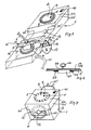
- a time switch 1 is provided, which is located in a housing 3, which in a manner known per se is a time setting element, for example a time setting disc 2 Socket 4 and optionally a switch 10.
- the timer 1 also has a clockwork, not shown, in the housing 3, which actuates the time setting disc 2.
- Adjusting members 8 are provided on the adjusting disk 2, for example in the circumferential direction, each of which is assigned, for example, 15 minutes to the adjusting disk 2 designed for 24 hours. This means that when a setting member 8 is actuated, the socket 4 is supplied with power for 15 minutes when the time setting member 8 is turned past a mark 9 by the clockwork.
- the switch 10 defines in its one position that the socket 4 is supplied with current when the setting member 8 is actuated. In its other position switches the timer is ineffective and the device connected to the timer via cable 6 is continuously put into operation.
- the timer 1 is connected to the network via a cable 11.
- the power supply to a device connected via the cable 6 to the plug 5, for example a television set is effected as a function of the position of the time setting disk 2.
- a device connected via the cable 6 to the plug 5 for example a television set
- the present device reliably prevents a change in this time specified for commissioning, for example by plugging the plug 5 into another socket or by reprogramming the time setting disk 2 or by actuating the switch 10.
- a preferred embodiment of the present device essentially has a bow-like part 12, which has an opening 13 through which the cable 6 can be passed, and which is thereby fastened to the housing 3 of the timer 1, which is an essential part of the circumference of the housing 3 in the region of the socket 4.
- the opening 13 in the bow-like part 12 is connected via a channel-shaped recess 14 to a side edge of the bow-like part 12, so that the cable 6 can be inserted into the opening 13 at any time without the connection between the plug 5 and the connector connected device must be interrupted.
- the bracket Preferably surrounds the bracket in the form shown the entire circumference of the housing 3 in the region of the socket 4, wherein it is interrupted at one point and has angled flanges 15, 15 which have openings through which the shackle 16 of a conventional lock 17 for locking the shackle-like part 12 can be passed.
- it can preferably have a weak point or a hinge 18 on the side opposite the flanges 15, 15 which enables it to expand.
- the bow-like part 12 is expediently firmly connected via a web part 19 or directly to a plate-shaped part 20 which serves to cover the adjusting disc 2 and, if appropriate, the switch 10.
- the part 20 is part of the present device.
- the preferably one-piece construction between the parts 12, 20 and possibly 19 enables them to be fastened to the housing 3 of the time switch 1 at the same time with the aid of a single locking device 17.
- the plate-shaped part 20 can be made to the housing 3 have complementary side walls 20 'which enclose the housing 3 in a cap-like manner.
- a locking device can also be provided, with which a region of the present device, for example the web part 19, can be locked on the surface of the housing 3 lying against it or the plate-shaped part 20 on the surface of the housing 3 lying against it is.
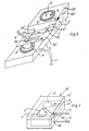
- a lock 21 is fastened to the web part 19 or to the plate 20 on the side facing the housing 3, which lock can be actuated from the side opposite the housing 3 by a key 22 which runs through a keyhole located in the part 19 or 20 .
- locking bolts 23, preferably on opposite sides of the lock 21 are retracted and extended in such a way that they overlap the edge of an opening 24 in a wall 3 'of the housing 3 below the part 19 or 20 or not.
- an advantage of the invention is that it can be used in connection with any time switch on the market, the parts 12 or 12 'and 20 being individually adapted to the shape and structure of the time switch. This means that it must only be achieved by the present device that it has surfaces which cover the socket 4, possibly the switch 10 and the shim 2 and that it can be effectively locked in any manner on the housing 3, the Socket 4 covering area has the described recess or opening 13 for passing the cable 6.
- FIG. 4 shows a time switch provided with the present device, which is constructed differently from the time switch of FIGS. 1 and 3. Details of FIG. 4, which have already been described in connection with FIGS. 1 and 3, are shown in FIG designated accordingly. As can be seen, in this embodiment the plate-like element 12 'is attached directly to the plate 20. It can also be seen that the mains connection 11 'can also be arranged directly on the housing 3.
- Timers are also known in which the socket is integrated in the time setting element.
- the socket and the time-setting disk and, if appropriate, the switch can be covered by a single plate which can be locked on the housing or the like.
- the invention relates to a device which prevents the plug 5 from being removed from the socket 4 of the timer 1 and which at the same time makes it impossible to actuate the time-setting element 2, and possibly the plug 10.
- the device preferably has plate-like elements which at least partially cover the time-setting element 2, the plug 10 and the plug 5 located in the socket 4.
- the exact shape of the device depends on the particular shape of the timer 1.
- the arrangement in particular of a locking device e.g. of the type described in connection with FIG. 2 can take place at any desired point on the housing 1, for example in the area of the plate 20, the side walls 20 '(see FIG. 3) or the plate-like part 12'.
- the cables 1, 6 mentioned can also be guided through a single opening.
- the openings mentioned preferably have the form of slots or cutouts which open to a housing edge on which the two housing parts 42 ′, 42 ′′ rest against one another in the closed state of the housing.
Landscapes
- Physics & Mathematics (AREA)
- General Physics & Mathematics (AREA)
- Details Of Connecting Devices For Male And Female Coupling (AREA)
- Electric Clocks (AREA)
Applications Claiming Priority (2)
| Application Number | Priority Date | Filing Date | Title |
|---|---|---|---|
| DE4011735A DE4011735A1 (de) | 1990-04-11 | 1990-04-11 | Verschliessbare vorrichtung zum sichern eines elektrogeraetes vor missbrauch |
| DE4011735 | 1990-04-11 |
Publications (2)
| Publication Number | Publication Date |
|---|---|
| EP0451840A2 true EP0451840A2 (fr) | 1991-10-16 |
| EP0451840A3 EP0451840A3 (en) | 1992-08-26 |
Family
ID=6404224
Family Applications (1)
| Application Number | Title | Priority Date | Filing Date |
|---|---|---|---|
| EP19910105780 Withdrawn EP0451840A3 (en) | 1990-04-11 | 1991-04-11 | Device for the prevention of misuse of an electrical timer switch |
Country Status (2)
| Country | Link |
|---|---|
| EP (1) | EP0451840A3 (fr) |
| DE (1) | DE4011735A1 (fr) |
Cited By (4)
| Publication number | Priority date | Publication date | Assignee | Title |
|---|---|---|---|---|
| DE19948326A1 (de) * | 1999-10-07 | 2001-04-12 | Wolfgang Eichelmann | Videospielanlage |
| GB2380815A (en) * | 2001-10-12 | 2003-04-16 | Malcolm Burgess | Timer limiting electrical equipment use |
| GB2414119A (en) * | 2004-05-15 | 2005-11-16 | John Stanley Aldridge | Lockable case for domestic electric timer |
| CN102868067A (zh) * | 2011-07-07 | 2013-01-09 | 鸿富锦精密工业(深圳)有限公司 | 插座 |
Families Citing this family (5)
| Publication number | Priority date | Publication date | Assignee | Title |
|---|---|---|---|---|
| DE10043023A1 (de) * | 2000-09-01 | 2002-03-21 | Audi Ag | Sicherungsvorrichtung zum Schutz des Aufhebens einer elektrischen Verbindung durch einen Nichtberechtigten |
| DE20114186U1 (de) | 2001-08-28 | 2001-11-22 | Kirchmeier, Rolf, 76706 Dettenheim | Steuerungseinrichtung zur Verwaltung der Nutzungszeiten eines elektrischen Geräts |
| DE10342366A1 (de) * | 2003-09-12 | 2005-04-07 | Frank Sperling | Schutzvorrichtung vor unbefugter Benutzung von Steckdosen |
| DE102007006550A1 (de) | 2007-02-09 | 2008-08-14 | Abb Ag | Installationsgerät mit einem kappenartigen Klappdeckel |
| DE102011110489A1 (de) * | 2011-08-17 | 2013-02-21 | Stefan Gervink | Steckdoseneinrichtung |
Family Cites Families (8)
| Publication number | Priority date | Publication date | Assignee | Title |
|---|---|---|---|---|
| US2588176A (en) * | 1950-10-06 | 1952-03-04 | Strauch John | Telephone lock |
| US2841658A (en) * | 1954-02-24 | 1958-07-01 | Dawkins Thomas | Locking device for dial telephones |
| US3833779A (en) * | 1973-05-18 | 1974-09-03 | L Leone | Television timer to regulate television viewing time |
| US4484220A (en) * | 1981-09-29 | 1984-11-20 | Idea Research Development Corp. | Television monitor |
| DE3703477A1 (de) * | 1987-02-05 | 1988-08-18 | Siemens Ag | Zeitschaltuhr |
| DE3802205A1 (de) * | 1988-01-26 | 1989-07-27 | Vught Barbara Van | Vorrichtung zur einstellung einer kommunikationsbereitschaft bei telefonapparaten |
| DE3805113A1 (de) * | 1988-02-18 | 1989-08-31 | Heibl Gmbh Apparatebau W | Buchsenanordnung fuer telekommunikationskabel |
| DE3807826A1 (de) * | 1988-03-10 | 1989-09-21 | Beco Einrichtungstechnik Gmbh | Vorrichtung zur warensicherung |
-
1990
- 1990-04-11 DE DE4011735A patent/DE4011735A1/de active Granted
-
1991
- 1991-04-11 EP EP19910105780 patent/EP0451840A3/de not_active Withdrawn
Cited By (6)
| Publication number | Priority date | Publication date | Assignee | Title |
|---|---|---|---|---|
| DE19948326A1 (de) * | 1999-10-07 | 2001-04-12 | Wolfgang Eichelmann | Videospielanlage |
| GB2380815A (en) * | 2001-10-12 | 2003-04-16 | Malcolm Burgess | Timer limiting electrical equipment use |
| GB2380815B (en) * | 2001-10-12 | 2005-05-25 | Malcolm Burgess | A television timer device |
| GB2414119A (en) * | 2004-05-15 | 2005-11-16 | John Stanley Aldridge | Lockable case for domestic electric timer |
| CN102868067A (zh) * | 2011-07-07 | 2013-01-09 | 鸿富锦精密工业(深圳)有限公司 | 插座 |
| CN102868067B (zh) * | 2011-07-07 | 2016-03-09 | 鸿富锦精密工业(深圳)有限公司 | 插座 |
Also Published As
| Publication number | Publication date |
|---|---|
| EP0451840A3 (en) | 1992-08-26 |
| DE4011735A1 (de) | 1991-12-05 |
| DE4011735C2 (fr) | 1992-03-19 |
Similar Documents
| Publication | Publication Date | Title |
|---|---|---|
| DE2143412A1 (de) | Türverriegelungssystem | |
| DE2629723C3 (de) | Handbetätigbare Einbauschaltvorrichtung für elektrische Maschinen | |
| DE3014639A1 (de) | Schaltervorrichtung | |
| EP0451840A2 (fr) | Dispositif pour la protection d'une minuterie électrique contre un usage illicite | |
| DE69726158T2 (de) | Starkstromschutzvorrichtung | |
| DE2630331A1 (de) | Vorrichtung zur diebstahlsicherung elektrisch betriebener geraete, insbesondere in kraftfahrzeugen | |
| EP3651282B1 (fr) | Bloc multiprise modulaire | |
| EP2624275B1 (fr) | Commutateur électrique | |
| EP2858186A1 (fr) | Adaptateur de barre omnibus | |
| DE69928878T2 (de) | Sicherheitsverbindungsvorrichtung, insbesondere für modulare elektrische Geräte | |
| DE69509350T2 (de) | Schlossbedienungsmechanismus mit einem zweiteiligen Gehäuse | |
| DE3134419A1 (de) | Electric terminal box | |
| DE102019219497A1 (de) | Manueller trennschalter mit steckverbinderpositionssicherung | |
| EP0473748B1 (fr) | Minuterie | |
| WO1985002488A1 (fr) | Minuterie de securite pour appareil de television ou autres | |
| DE3422896A1 (de) | Kontroll- bzw. stempeluhr | |
| DE2836974C2 (de) | Innenleuchte | |
| DE69700731T2 (de) | Installation der Stromversorgung elektrischer Verbraucher an Fahrzeugdächern | |
| DE19751674C2 (de) | Schaltungsanordnung mit Sicherheitsfunktion | |
| DE2461464C3 (de) | Elektronisches Zeitrelais | |
| DE3540430C2 (de) | Elektrische Verbinderanordnung | |
| DE9201409U1 (de) | Sperrvorrichtung gegen Betätigung, insbesondere Wiedereinschalten von Installationsgeräten | |
| EP0118389B1 (fr) | Appareil de commutation électrique pour la surveillance et la commande de connexions de commutation | |
| DE4218660C1 (de) | Profilzylinderschaltschloß | |
| EP0370375B1 (fr) | Dispositif de sécurité pour une armoire avec ouverture d'accès |
Legal Events
| Date | Code | Title | Description |
|---|---|---|---|
| PUAI | Public reference made under article 153(3) epc to a published international application that has entered the european phase |
Free format text: ORIGINAL CODE: 0009012 |
|
| AK | Designated contracting states |
Kind code of ref document: A2 Designated state(s): AT BE CH DE DK ES FR GB GR IT LI LU NL SE |
|
| RBV | Designated contracting states (corrected) |
Designated state(s): AT CH DE FR GB IT LI |
|
| PUAL | Search report despatched |
Free format text: ORIGINAL CODE: 0009013 |
|
| AK | Designated contracting states |
Kind code of ref document: A3 Designated state(s): AT BE CH DE DK ES FR GB GR IT LI LU NL SE |
|
| STAA | Information on the status of an ep patent application or granted ep patent |
Free format text: STATUS: THE APPLICATION IS DEEMED TO BE WITHDRAWN |
|
| 18D | Application deemed to be withdrawn |
Effective date: 19930301 |