EP0451885B1 - Appareil audio ou vidéo à haut-parleur encastré - Google Patents
Appareil audio ou vidéo à haut-parleur encastré Download PDFInfo
- Publication number
- EP0451885B1 EP0451885B1 EP91200498A EP91200498A EP0451885B1 EP 0451885 B1 EP0451885 B1 EP 0451885B1 EP 91200498 A EP91200498 A EP 91200498A EP 91200498 A EP91200498 A EP 91200498A EP 0451885 B1 EP0451885 B1 EP 0451885B1
- Authority
- EP
- European Patent Office
- Prior art keywords
- loud
- speaker
- channel
- housing
- audio
- Prior art date
- Legal status (The legal status is an assumption and is not a legal conclusion. Google has not performed a legal analysis and makes no representation as to the accuracy of the status listed.)
- Expired - Lifetime
Links
Images
Classifications
-
- H—ELECTRICITY
- H04—ELECTRIC COMMUNICATION TECHNIQUE
- H04B—TRANSMISSION
- H04B1/00—Details of transmission systems, not covered by a single one of groups H04B3/00 - H04B13/00; Details of transmission systems not characterised by the medium used for transmission
- H04B1/06—Receivers
- H04B1/08—Constructional details, e.g. cabinet
-
- H—ELECTRICITY
- H04—ELECTRIC COMMUNICATION TECHNIQUE
- H04N—PICTORIAL COMMUNICATION, e.g. TELEVISION
- H04N5/00—Details of television systems
- H04N5/44—Receiver circuitry for the reception of television signals according to analogue transmission standards
- H04N5/60—Receiver circuitry for the reception of television signals according to analogue transmission standards for the sound signals
-
- H—ELECTRICITY
- H04—ELECTRIC COMMUNICATION TECHNIQUE
- H04R—LOUDSPEAKERS, MICROPHONES, GRAMOPHONE PICK-UPS OR LIKE ACOUSTIC ELECTROMECHANICAL TRANSDUCERS; ELECTRIC HEARING AIDS; PUBLIC ADDRESS SYSTEMS
- H04R1/00—Details of transducers, loudspeakers or microphones
- H04R1/20—Arrangements for obtaining desired frequency or directional characteristics
- H04R1/32—Arrangements for obtaining desired frequency or directional characteristics for obtaining desired directional characteristic only
- H04R1/34—Arrangements for obtaining desired frequency or directional characteristics for obtaining desired directional characteristic only by using a single transducer with sound reflecting, diffracting, directing or guiding means
- H04R1/345—Arrangements for obtaining desired frequency or directional characteristics for obtaining desired directional characteristic only by using a single transducer with sound reflecting, diffracting, directing or guiding means for loudspeakers
-
- B—PERFORMING OPERATIONS; TRANSPORTING
- B60—VEHICLES IN GENERAL
- B60R—VEHICLES, VEHICLE FITTINGS, OR VEHICLE PARTS, NOT OTHERWISE PROVIDED FOR
- B60R11/00—Arrangements for holding or mounting articles, not otherwise provided for
- B60R11/02—Arrangements for holding or mounting articles, not otherwise provided for for radio sets, television sets, telephones, or the like; Arrangement of controls thereof
- B60R11/0217—Arrangements for holding or mounting articles, not otherwise provided for for radio sets, television sets, telephones, or the like; Arrangement of controls thereof for loud-speakers
Definitions
- the invention relates to an audio or video apparatus comprising a housing and a loud-speaker incorporated in the housing, in which the housing accommodates an acoustic channel at one end opening into an aperture in a side of the housing, the loud-speaker acoustically cooperates with the channel and the diaphragm of the loud-speaker thereto forms part of the wall of the acoustic channel, the acoustic channel has a perpendicular cross-section which continues to augment viewed in the direction of the aperture in said side, and the length of the loud-speaker viewed in the longitudinal direction of the acoustic channel is greater than or equal to half the length of the acoustic channel.
- An apparatus of this kind is known from British Patent Specification No. 735,402.
- An application in a television set is discussed in that Specification.
- an application in a radio for example, a car radio could also be considered in this respect.
- the car radio housing generally comprises all the electronics required for this application. Said side is the front side of the car radio which is visible and remains accessible if the car radio has been installed in the appropriate aperture in the facia of the motor car.
- the audio or video apparatus is characterized in that the loud-speaker is arranged in the channel and the channel is formed in a manner such that for a part of the loud-speaker diaphragm, the size of said part being greater than or equal to half the surface area of the diaphragm, it holds that lines perpendicular to this part of the diaphragm surface, once they have been reflected by the channel surface one time, are not directed at said aperture, said lines forming equal angles of incidence and reflection to the channel surface and that the smallest dimension of said aperture is less than one half of the largest dimension of the loudspeaker.
- the invention is based on the concept that it is possible to incorporate relatively large loud-speakers in audio or video apparatus, whereas the housing of the apparatus can yet remain compact. This is particularly achieved when allowing the diaphragm of the loud-speaker to constitute a large part of the wall of the acoustic channel.
- EP-A-0 353 092 shows a horn-equipped loudspeaker, whereby the loudspeaker diaphragm is formed of a portion of one of the walls of the horn.
- the United States Patent No. 2,440,078 also does not disclose that the smallest dimension of said aperture is less than one half of the largest dimension of the loudspeaker. With this measure it has become possible, for example, to install a reasonably large loud-speaker in a car radio.
- the dimensions of car radios are standardized at 50 mm height, 180 mm width and 149 mm depth.
- the front side does not have an aperture for accommodating a reasonably large loud-speaker, which loud-speaker is able to reproduce low-frequency signals having a sufficient level.
- a cavity for accommodating a reasonably large loud-speaker is developed inside the housing.
- the loud-speaker in a horizontal (or tilted) fashion in the housing.
- the acoustic signals generated by the loud-speaker can reach the passenger compartment of the motor car.
- this facia can function as an acoustic baffle so that the low-frequency reproduction is favourable.
- a single wideband loud-speaker installed in the housing will then be sufficient. This implies that no additional wiring in the motor car itself needs to be arranged for connecting one or more loud-speakers/loud-speakers enclosures.
- the loud-speaker installed in the housing could be a woofer.
- the car radio should be provided with terminals for supplying relevant electrical signals to at least two squawkers which are then installed elsewhere in the motor car compartment in a stereo arrangement.
- the acoustic channel preferably has the form of an acoustic horn. This achieves a proper transmission between the mechanical vibrations of the loud-speaker diaphragm and the acoustic signal supplied by the car radio, more specifically, if also higher frequency audio signals are reproduced through the loud-speaker.
- the car radio may further be characterised in that the loud-speaker is arranged for reproducing a low-frequency audio signal, in that the car radio further includes second and third loud-speakers arranged for reproducing a higher frequency portion of a respective left or right signal portion of a stereo signal, and in that the second and third loud-speakers are mechanically coupled to said side of the housing.
- the loud-speaker is arranged for reproducing a low-frequency audio signal
- the car radio further includes second and third loud-speakers arranged for reproducing a higher frequency portion of a respective left or right signal portion of a stereo signal
- the second and third loud-speakers are mechanically coupled to said side of the housing.
- the second and third loud-speakers are coupled each to said side of the housing by means of a support, whilst being adjustable with respect to the housing, an acceptable stereo reproduction is feasible with a car radio of this kind.
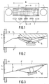
- Fig. 1 shows a front elevation of the car radio according to the invention.
- the front side comprises a plurality of controls.
- a volume control knob 1 a knob 2 for station tuning and push buttons 3, for example, for selecting the frequency range such as FM, MW, LW or USW.
- the front side of the car radio further has an aperture 4 which, for example, behind a grille 5.
- the grille 5 is not necessary.
- the aperture 4 has a rectangular shape and a width-to-height proportion of, for example, 3:1.
- the width of the aperture 4 corresponds approximately to the diameter of the loud-speaker 6 incorporated in the car radio, cf. Fig. 2, it may be assumed that the height of the aperture 4 is about equal to 1/3 of the diameter of the loud-speaker 6. The height of the aperture 4, however, may also be taken smaller, which is to say, smaller than 1/3 of the diameter of the loud-speaker 6.
- Fig. 2 shows a cross-sectional view of the car radio along line A-A in Fig. 1, when installed in a facia 10 of a motor car.
- Fig. 2 shows a loud-speaker 6 accommodated in the housing 7 of the car radio.
- the loud-speaker is a cone loud-speaker of the electrodynamic type. These loud-speakers are known per se and need no further explanation.
- the loud-speaker 6 acoustically cooperates with a channel 8 which is also accommodated in the housing of the car radio. One end of the channel opens into the aperture 4 in the front side of the car radio. Mechanical vibrations of the diaphragm 9 of the converter 6 are converted into acoustic waves reaching the motor car compartment through the channel 8 and the aperture 4.
- the loud-speaker 6 is installed in the wall of the acoustic channel 8.
- the width of the channel 8 may be the same over the entire length of the channel and then, for example, be equal to the width 10 of the aperture 4
- the housing includes a shaping portion 11′ to give the channel a cross-section which continues to augment viewed in the direction of the aperture 4. Viewed in this longitudinal direction of the channel 8 the loud-speaker 6 has a dimension which is larger than or equal to half the length of the channel 8. Preferably, the size of the surface of the diaphragm is at least a quarter of the surface of the channel 8.
- the channel 8 and the cavity 9′ in the housing behind the loud-speaker 6 are acoustically separated to avoid acoustic short circuiting.
- the cavity 9′ comprises the car radio electronics.
- the channel is preferably provided to have a cross-section which augments, viewed in the direction of the aperture 4. This could be realised by allowing the width and/or height of the channel 8 towards the aperture 4 to augment ever more. This is shown in Fig. 3 which likewise depicts a cross-sectional view along line A-A′ of Fig. 1. In this respect it is assumed that the width of the channel 8 is constant and the height h augments.
- the loud-speaker 6′ is now a planar diaphragm loud-speaker also of the electrodynamic type, which is installed in the housing 7 in a slightly tilted fashion with respect to the arrangement of Fig. 1.
- the loud-speaker 6′ is accommodated in the wall of the channel 8′.
- Fig. 4 shows yet another cross-sectional view.
- the loud-speaker 6 is installed a little more to the front of the car radio. However, this is not essential.
- the channel 8 ⁇ here has a conventional flared horn shape.
- the width of the channel 8 ⁇ is again taken as a constant value, for example, equal to b, cf. Fig. 1.
- the height h′ again becomes larger viewed in the direction of the aperture 4, so that the channel 8 ⁇ in the plane of the drawing has the shape of a flared horn. This is realised by introducing a moulding 11 of the desired shape against the top of the housing 7.
- a more or less horn-shaped channel could have been realised by introducing a moulding 11′ into the channel 8 against the top side of the housing 7 exactly above the converter 6.
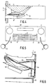
- Fig. 5 shows yet another exemplary embodiment.
- the loud-speaker is not shown in Fig. 5, but radiates downwardly into an acoustic channel which opens into the aperture 4′.
- Fig. 5 an aperture 20 for inserting cassette tapes is indicated.
- the end 4′ of the channel 8′′′ is again closed by means of a grille 5′.
- the loud-speaker (not shown) is in this case, for example, a woofer which only reproduces a low-frequency audio signal.
- the car radio further includes second and third loud-speakers 23, 24 respectively.
- the loud-speaker 23 is intended to reproduce the left signal portion of the stereo signal.
- the loud-speaker 23 is a tweeter or a squawker.
- the loud-speaker 24 is also a tweeter or a squawker and is intended to reproduce the right signal portion of the stereo signal.
- the loud-speakers 23 and 24 are mechanically coupled to the front side of the car radio. The mechanical coupling may be detachable if need be.
- Fig. 5 shows that the two loud-speakers are coupled to the front side of the car radio by means of supports 25 and 26 respectively.
- the loud-speakers are adjustable with respect to the car radio.
- the loud-speakers may be positioned in a direction so that they provide maximum stereo reproduction for the passenger(s) in the motor car compartment.
- the electric supply wires to the loud-speakers 23 and 24 may be led through the supports 25 and 26.
- An advantage of a car radio of this kind is that no external wiring to the loud-speakers elsewhere in the motor car compartment is necessary and furthermore, the installation is very simple.
- the car radio together with the loud-speakers may be inserted at one time in the appropriate aperture in the facia and is then ready for use. It will be self-evident that the loud-speakers 23 and 24, in view of safety aspects, must not have sharply protruding parts.
- the facia operates as a baffle for the acoustic signals emanating from the loud-speaker 6.
- Fig. 6 shows an application in a television set.
- Fig. 6 shows a cross-sectional view of the loud-speaker and acoustic channel, showing only part of the housing 60 of the television set and the picture tube 61.
- the loud-speaker 62 has a diameter which is about as large as the length of channel 63.
- a grille 64 is installed before the sound exit of the channel 63 .
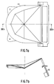
- the channel 63 is in this case formed by the loud-speaker itself and a shaping portion 65 shown in greater detail in Fig. 7.
- Fig. 7b shows a cross-sectional view of the shaping portion along the line b-b in Fig. 7a, whilst Fig. 7a shows a plan view of the shaping portion.
Landscapes
- Engineering & Computer Science (AREA)
- Signal Processing (AREA)
- Health & Medical Sciences (AREA)
- Otolaryngology (AREA)
- Computer Networks & Wireless Communication (AREA)
- Physics & Mathematics (AREA)
- Acoustics & Sound (AREA)
- Multimedia (AREA)
- Fittings On The Vehicle Exterior For Carrying Loads, And Devices For Holding Or Mounting Articles (AREA)
- Details Of Audible-Bandwidth Transducers (AREA)
- Obtaining Desirable Characteristics In Audible-Bandwidth Transducers (AREA)
Claims (10)
- Appareil audio ou vidéo comprenant un boîtier (7) et un haut-parleur (6, 6′, 62) incorporé au boîtier (7), dans lequel le boîtier (7) contient un canal acoustique (8, 8′, 63) s'ouvrant à une extrémité dans une ouverture (4, 4′) ménagée dans un côté du boîtier (7), le haut-parleur (6, 6′, 62) coopère au plan acoustique avec le canal (8, 8′, 63) et le diaphragme du haut-parleur fait partie de la paroi (65) du canal acoustique (8, 8′, 63), ledit canal acoustique (8, 8′, 63) a une section transversale perpendiculaire qui augmente sans discontinuer dans la direction de l'ouverture (4, 4′) dudit côté, et la longueur du haut-parleur (6, 6′, 62), vu dans la direction longitudinale du canal acoustique (8, 8′, 63), est supérieure ou égale à la moitié de la longueur dudit canal acoustique (8, 8′, 63), le haut-parleur (6, 6′, 62) étant agencé dans le canal (8, 8′, 63), caractérisé en ce que le canal (8, 8′, 82) est formé d'une manière telle que, pour une partie du diaphragme (9) du haut-parleur, la dimension de ladite partie étant supérieure ou égale à la moitié de la surface du diaphragme (9), il s'avère que les lignes perpendiculaires à cette partie de la surface du diaphragme, dès qu'elles ont été réfléchies une fois par la surface du canal, ne sont pas dirigées vers ladite ouverture (4, 4′), ces lignes formant des angles égaux d'incidence et de réflexion vis-à-vis de la surface du canal, et en ce que la dimension la plus petite de ladite ouverture (4, 4′) est inférieure à la moitié de la dimension la plus grande du haut-parleur (6, 6′, 62).
- Appareil audio ou vidéo selon la revendication 1, caractérisé en ce que la dimension de la surface du diaphragme (9) constitue au moins un quart de la surface du canal acoustique (8, 8′, 63).
- Appareil audio ou vidéo selon la revendication 1 ou 2, caractérisé en ce que le haut-parleur (6, 6′, 62) est un haut-parleur à cône et la partie de la paroi du canal opposée au haut-parleur (6, 6′, 62) a une forme qui est adaptée à la forme du cône de haut-parleur (9).
- Appareil audio ou vidéo selon la revendication 3, caractérisé en ce que le canal (8, 8′, 63) comprend une pièce moulée (65).
- Appareil audio ou vidéo selon l'une quelconque des revendications 1 à 4, caractérisé en ce que le canal acoustique (8, 8′, 63) a la forme d'un pavillon acoustique.
- Appareil audio ou vidéo selon l'une quelconque des revendications précédentes, caractérisé en ce que le haut-parleur (6, 6′, 62) est un haut-parleur de graves.
- Appareil audio selon la revendication 6, sous la forme d'un autoradio, caractérisé en ce que le haut-parleur (6, 6′, 62) est prévu pour reproduire un signal audio de basses fréquences, que l'autoradio comprend, en outre, un deuxième et un troisième haut-parleurs (23, 24) prévus pour reproduire une partie de fréquence supérieure d'une partie de signal gauche ou droite respective d'un signal stéréo, et que le deuxième et le troisième haut-parleurs sont mécaniquement couplés audit côté du boîtier.
- Autoradio selon la revendication 7, caractérisé en ce que le deuxième et troisième haut-parleurs sont couplés chacun audit côté du boîtier à l'aide d'un support (25, 26).
- Autoradio selon la revendication 8, caractérisé en ce que le deuxième et le troisième haut-parleurs (23, 24) sont réglables par rapport au boîtier.
- Autoradio selon la revendication 9, caractérisé en ce que les supports (25, 26) sont réglables par rapport au boîtier.
Applications Claiming Priority (2)
| Application Number | Priority Date | Filing Date | Title |
|---|---|---|---|
| NL9000570A NL9000570A (nl) | 1990-03-13 | 1990-03-13 | Audio- of videoapparaat met ingebouwde luidspreker. |
| NL9000570 | 1990-03-13 |
Publications (2)
| Publication Number | Publication Date |
|---|---|
| EP0451885A1 EP0451885A1 (fr) | 1991-10-16 |
| EP0451885B1 true EP0451885B1 (fr) | 1995-06-28 |
Family
ID=19856733
Family Applications (1)
| Application Number | Title | Priority Date | Filing Date |
|---|---|---|---|
| EP91200498A Expired - Lifetime EP0451885B1 (fr) | 1990-03-13 | 1991-03-08 | Appareil audio ou vidéo à haut-parleur encastré |
Country Status (7)
| Country | Link |
|---|---|
| US (1) | US5471018A (fr) |
| EP (1) | EP0451885B1 (fr) |
| JP (1) | JPH04220898A (fr) |
| KR (1) | KR100202342B1 (fr) |
| DE (1) | DE69110731T2 (fr) |
| HK (1) | HK165096A (fr) |
| NL (1) | NL9000570A (fr) |
Families Citing this family (22)
| Publication number | Priority date | Publication date | Assignee | Title |
|---|---|---|---|---|
| EP0746958B1 (fr) * | 1994-12-23 | 2001-10-10 | Koninklijke Philips Electronics N.V. | Dispositif de reproduction sonore comprenant un pavillon acoustique et pavillon acoustique destine a ce dispositif |
| JP3171542B2 (ja) * | 1995-05-26 | 2001-05-28 | 三洋電機株式会社 | スピーカ装置及びこれを用いたテレビジョン受像機 |
| GB2310559B (en) * | 1996-02-23 | 2000-09-20 | Nokia Mobile Phones Ltd | Audio output apparatus for a mobile communication device |
| DE19612481C2 (de) * | 1996-03-29 | 2003-11-13 | Sennheiser Electronic | Elektrostatischer Wandler |
| DE19734120A1 (de) * | 1997-08-07 | 1999-02-18 | Nokia Deutschland Gmbh | Tonwiedergabeanordnung |
| JP3732007B2 (ja) * | 1998-04-30 | 2006-01-05 | ティーオーエー株式会社 | ホーンスピーカ |
| JP2001025099A (ja) * | 1999-07-07 | 2001-01-26 | Matsushita Electric Ind Co Ltd | 音響再生装置 |
| US7433483B2 (en) | 2001-02-09 | 2008-10-07 | Thx Ltd. | Narrow profile speaker configurations and systems |
| US7457425B2 (en) * | 2001-02-09 | 2008-11-25 | Thx Ltd. | Vehicle sound system |
| US7254239B2 (en) * | 2001-02-09 | 2007-08-07 | Thx Ltd. | Sound system and method of sound reproduction |
| US7093688B2 (en) * | 2001-09-05 | 2006-08-22 | Samsung Electronics Co., Ltd. | Structure for preventing the generation of standing waves and a method for implementing the same |
| CN1647579B (zh) * | 2002-03-05 | 2014-11-26 | 音响制品国际公司 | 带有成形声场的扬声器 |
| DE102006023909B3 (de) * | 2006-05-19 | 2007-07-19 | Daimlerchrysler Ag | Bandpassbox in der Tragstruktur eines Fahrzeuges |
| GB2442260A (en) * | 2006-09-29 | 2008-04-02 | Martin Audio Ltd | Loudspeaker diaphragm conforms to surrounding acoustic surface |
| US8666104B2 (en) * | 2009-04-02 | 2014-03-04 | Mitek Corp., Inc. | Lighting and audio communication system |
| US8300869B2 (en) * | 2009-04-02 | 2012-10-30 | Mitek Corp., Inc. | Lighting and audio communication system |
| CN102696238B (zh) * | 2010-11-10 | 2017-02-15 | 松下知识产权经营株式会社 | 扬声器、以及具备该扬声器的音响设备 |
| EP2974356B1 (fr) | 2013-03-13 | 2020-05-06 | THX Ltd | Haut-parleur compact |
| JP5804433B2 (ja) * | 2014-03-28 | 2015-11-04 | 裕昭 谷本 | スピーカ装置およびスピーカ装置の組立セット |
| US10785560B2 (en) * | 2016-05-09 | 2020-09-22 | Samsung Electronics Co., Ltd. | Waveguide for a height channel in a speaker |
| JP7139272B2 (ja) | 2019-03-20 | 2022-09-20 | 株式会社トランストロン | 車載装置 |
| CN111818420B (zh) * | 2019-09-17 | 2023-04-07 | 华为技术有限公司 | 扬声器及终端 |
Family Cites Families (10)
| Publication number | Priority date | Publication date | Assignee | Title |
|---|---|---|---|---|
| FR353092A (fr) * | 1905-04-06 | 1905-09-01 | Pierre Maillard | Essieu d'une seule pièce avec différentiel dédoublé pour automobiles |
| CH188456A (de) * | 1935-12-23 | 1936-12-31 | Funk Max | Radioapparat. |
| US2440078A (en) * | 1943-03-17 | 1948-04-20 | Gen Electric | Radio cabinet and speaker mounting |
| US2642948A (en) * | 1948-05-28 | 1953-06-23 | Rca Corp | Portable radio with a bass-reflex cabinet |
| GB735402A (en) * | 1953-07-23 | 1955-08-17 | Gen Electric Co Ltd | Improvements in or relating to television receivers |
| FR1204957A (fr) * | 1958-10-18 | 1960-01-29 | Perfectionnement aux dispositifs de reproduction électro-acoustique avec effet de relief | |
| US3583238A (en) * | 1969-02-24 | 1971-06-08 | Fmc Corp | Mechanism and method for mounting wheel on testing apparatus |
| US4199657A (en) * | 1978-07-21 | 1980-04-22 | Harvey Lane | Planar sound reproducing speaker system |
| US4541188A (en) * | 1983-02-04 | 1985-09-17 | Talkies International Corp. | Reflective audio assembly and picture |
| KR910004063A (ko) * | 1988-07-28 | 1991-02-28 | 파브리-꽁띠 루까 | 고충실도 음을 재생하는 장치 및 방법 |
-
1990
- 1990-03-13 NL NL9000570A patent/NL9000570A/nl not_active Application Discontinuation
-
1991
- 1991-02-28 US US07/662,045 patent/US5471018A/en not_active Expired - Fee Related
- 1991-03-08 KR KR1019910003720A patent/KR100202342B1/ko not_active Expired - Fee Related
- 1991-03-08 EP EP91200498A patent/EP0451885B1/fr not_active Expired - Lifetime
- 1991-03-08 DE DE69110731T patent/DE69110731T2/de not_active Expired - Fee Related
- 1991-03-11 JP JP3069522A patent/JPH04220898A/ja active Pending
-
1996
- 1996-09-05 HK HK165096A patent/HK165096A/en not_active IP Right Cessation
Also Published As
| Publication number | Publication date |
|---|---|
| KR910017867A (ko) | 1991-11-05 |
| EP0451885A1 (fr) | 1991-10-16 |
| NL9000570A (nl) | 1991-10-01 |
| JPH04220898A (ja) | 1992-08-11 |
| KR100202342B1 (ko) | 1999-06-15 |
| DE69110731D1 (de) | 1995-08-03 |
| HK165096A (en) | 1996-09-13 |
| US5471018A (en) | 1995-11-28 |
| DE69110731T2 (de) | 1996-02-22 |
Similar Documents
| Publication | Publication Date | Title |
|---|---|---|
| EP0451885B1 (fr) | Appareil audio ou vidéo à haut-parleur encastré | |
| US4696037A (en) | Loudspeaker arrangement comprising one or more flat diaphragms | |
| US6035051A (en) | Sound apparatus | |
| EP0588354B1 (fr) | Haut-parleur démontable pour un récepteur de télévision | |
| US4646349A (en) | Equipment for the stereophonic sound reproduction in a television receiver | |
| US4224469A (en) | Stereo speaker system | |
| FI93070C (fi) | Äänijärjestelmä, erityisesti televisiovastaanottimiin tarkoitettu stereofoninen äänijärjestelmä, jossa on siihen integroituna mitoiltaan suuri matalien taajuuksien kaiutin | |
| US5710821A (en) | Audio communications system with built in expansion capability for a desktop computer | |
| US4502149A (en) | Multi-purpose interchangeable modular auto loudspeaker system | |
| WO2004021741A1 (fr) | Haut-parleur elliptique encastre | |
| US6343132B1 (en) | Loudspeaker | |
| EP0722650B1 (fr) | Haut-parleur, dispositif integrant un haut-parleur, et enceinte pour haut-parleur | |
| US20020081980A1 (en) | Sound reproduction apparatus for use in vehicular audio applications | |
| FI90711B (fi) | Televisiovastaanotin | |
| KR100473714B1 (ko) | 스피커 시스템 | |
| JPH05191758A (ja) | 透過形ビデオプロジェクタにおけるスピーカ装置 | |
| CN214851677U (zh) | 一种多功能长条音响 | |
| CN217770279U (zh) | 显示设备及其条形音箱 | |
| CN219577242U (zh) | 一种线性阵列组合音箱 | |
| CN217240846U (zh) | 组合条形音箱 | |
| CN217693597U (zh) | 显示设备及其条形音箱 | |
| CN210807470U (zh) | 多功能高低音电视喇叭 | |
| HK105595A (en) | Loudspeaker boxes for a television set and other apparatuses | |
| EP0910226B1 (fr) | Téléviseur avec haut-parleurs et décodeur pour signaux audio à effet spatial | |
| KR100218095B1 (ko) | 텔레비젼용 스피커 시스템 |
Legal Events
| Date | Code | Title | Description |
|---|---|---|---|
| PUAI | Public reference made under article 153(3) epc to a published international application that has entered the european phase |
Free format text: ORIGINAL CODE: 0009012 |
|
| AK | Designated contracting states |
Kind code of ref document: A1 Designated state(s): DE FR GB IT |
|
| 17P | Request for examination filed |
Effective date: 19920415 |
|
| 17Q | First examination report despatched |
Effective date: 19931202 |
|
| GRAA | (expected) grant |
Free format text: ORIGINAL CODE: 0009210 |
|
| AK | Designated contracting states |
Kind code of ref document: B1 Designated state(s): DE FR GB IT |
|
| REF | Corresponds to: |
Ref document number: 69110731 Country of ref document: DE Date of ref document: 19950803 |
|
| ITF | It: translation for a ep patent filed | ||
| ET | Fr: translation filed | ||
| PLBE | No opposition filed within time limit |
Free format text: ORIGINAL CODE: 0009261 |
|
| STAA | Information on the status of an ep patent application or granted ep patent |
Free format text: STATUS: NO OPPOSITION FILED WITHIN TIME LIMIT |
|
| 26N | No opposition filed | ||
| REG | Reference to a national code |
Ref country code: FR Ref legal event code: CD |
|
| PGFP | Annual fee paid to national office [announced via postgrant information from national office to epo] |
Ref country code: FR Payment date: 20000328 Year of fee payment: 10 |
|
| PGFP | Annual fee paid to national office [announced via postgrant information from national office to epo] |
Ref country code: GB Payment date: 20000331 Year of fee payment: 10 |
|
| PGFP | Annual fee paid to national office [announced via postgrant information from national office to epo] |
Ref country code: DE Payment date: 20000524 Year of fee payment: 10 |
|
| PG25 | Lapsed in a contracting state [announced via postgrant information from national office to epo] |
Ref country code: GB Free format text: LAPSE BECAUSE OF NON-PAYMENT OF DUE FEES Effective date: 20010308 |
|
| GBPC | Gb: european patent ceased through non-payment of renewal fee |
Effective date: 20010308 |
|
| PG25 | Lapsed in a contracting state [announced via postgrant information from national office to epo] |
Ref country code: FR Free format text: LAPSE BECAUSE OF NON-PAYMENT OF DUE FEES Effective date: 20011130 |
|
| REG | Reference to a national code |
Ref country code: FR Ref legal event code: ST |
|
| PG25 | Lapsed in a contracting state [announced via postgrant information from national office to epo] |
Ref country code: DE Free format text: LAPSE BECAUSE OF NON-PAYMENT OF DUE FEES Effective date: 20020101 |
|
| PG25 | Lapsed in a contracting state [announced via postgrant information from national office to epo] |
Ref country code: IT Free format text: LAPSE BECAUSE OF NON-PAYMENT OF DUE FEES;WARNING: LAPSES OF ITALIAN PATENTS WITH EFFECTIVE DATE BEFORE 2007 MAY HAVE OCCURRED AT ANY TIME BEFORE 2007. THE CORRECT EFFECTIVE DATE MAY BE DIFFERENT FROM THE ONE RECORDED. Effective date: 20050308 |