EP0451921B1 - Mischkopf zum Mischen flüssiger chemisch interreagierender plastischer Komponenten - Google Patents
Mischkopf zum Mischen flüssiger chemisch interreagierender plastischer Komponenten Download PDFInfo
- Publication number
- EP0451921B1 EP0451921B1 EP91200827A EP91200827A EP0451921B1 EP 0451921 B1 EP0451921 B1 EP 0451921B1 EP 91200827 A EP91200827 A EP 91200827A EP 91200827 A EP91200827 A EP 91200827A EP 0451921 B1 EP0451921 B1 EP 0451921B1
- Authority
- EP
- European Patent Office
- Prior art keywords
- plunger
- mixing
- plastic components
- mixing chamber
- mould
- Prior art date
- Legal status (The legal status is an assumption and is not a legal conclusion. Google has not performed a legal analysis and makes no representation as to the accuracy of the status listed.)
- Expired - Lifetime
Links
- 239000004033 plastic Substances 0.000 title claims description 18
- 229920003023 plastic Polymers 0.000 title claims description 18
- 239000007788 liquid Substances 0.000 title claims description 7
- 239000000203 mixture Substances 0.000 claims description 22
- 230000033001 locomotion Effects 0.000 claims description 17
- 238000000034 method Methods 0.000 claims description 5
- 210000000614 rib Anatomy 0.000 description 10
- 238000002347 injection Methods 0.000 description 9
- 239000007924 injection Substances 0.000 description 9
- 238000005086 pumping Methods 0.000 description 5
- 239000010408 film Substances 0.000 description 4
- 239000000919 ceramic Substances 0.000 description 3
- 238000004140 cleaning Methods 0.000 description 3
- 230000006835 compression Effects 0.000 description 2
- 238000007906 compression Methods 0.000 description 2
- 238000005187 foaming Methods 0.000 description 2
- 239000000463 material Substances 0.000 description 2
- 238000010926 purge Methods 0.000 description 2
- 239000004677 Nylon Substances 0.000 description 1
- 235000011483 Ribes Nutrition 0.000 description 1
- 241000220483 Ribes Species 0.000 description 1
- 238000004519 manufacturing process Methods 0.000 description 1
- 238000012986 modification Methods 0.000 description 1
- 230000004048 modification Effects 0.000 description 1
- 238000000465 moulding Methods 0.000 description 1
- 229920001778 nylon Polymers 0.000 description 1
- 238000006116 polymerization reaction Methods 0.000 description 1
- 239000011347 resin Substances 0.000 description 1
- 229920005989 resin Polymers 0.000 description 1
- 238000010008 shearing Methods 0.000 description 1
- 239000010409 thin film Substances 0.000 description 1
- 239000011345 viscous material Substances 0.000 description 1
Images
Classifications
-
- B—PERFORMING OPERATIONS; TRANSPORTING
- B29—WORKING OF PLASTICS; WORKING OF SUBSTANCES IN A PLASTIC STATE IN GENERAL
- B29B—PREPARATION OR PRETREATMENT OF THE MATERIAL TO BE SHAPED; MAKING GRANULES OR PREFORMS; RECOVERY OF PLASTICS OR OTHER CONSTITUENTS OF WASTE MATERIAL CONTAINING PLASTICS
- B29B7/00—Mixing; Kneading
- B29B7/74—Mixing; Kneading using other mixers or combinations of mixers, e.g. of dissimilar mixers ; Plant
- B29B7/76—Mixers with stream-impingement mixing head
- B29B7/7663—Mixers with stream-impingement mixing head the mixing head having an outlet tube with a reciprocating plunger, e.g. with the jets impinging in the tube
- B29B7/7673—Mixers with stream-impingement mixing head the mixing head having an outlet tube with a reciprocating plunger, e.g. with the jets impinging in the tube having additional mixing arrangements
-
- B—PERFORMING OPERATIONS; TRANSPORTING
- B29—WORKING OF PLASTICS; WORKING OF SUBSTANCES IN A PLASTIC STATE IN GENERAL
- B29B—PREPARATION OR PRETREATMENT OF THE MATERIAL TO BE SHAPED; MAKING GRANULES OR PREFORMS; RECOVERY OF PLASTICS OR OTHER CONSTITUENTS OF WASTE MATERIAL CONTAINING PLASTICS
- B29B7/00—Mixing; Kneading
- B29B7/74—Mixing; Kneading using other mixers or combinations of mixers, e.g. of dissimilar mixers ; Plant
- B29B7/76—Mixers with stream-impingement mixing head
- B29B7/7663—Mixers with stream-impingement mixing head the mixing head having an outlet tube with a reciprocating plunger, e.g. with the jets impinging in the tube
- B29B7/7684—Parts; Accessories
- B29B7/7689—Plunger constructions
-
- B—PERFORMING OPERATIONS; TRANSPORTING
- B29—WORKING OF PLASTICS; WORKING OF SUBSTANCES IN A PLASTIC STATE IN GENERAL
- B29B—PREPARATION OR PRETREATMENT OF THE MATERIAL TO BE SHAPED; MAKING GRANULES OR PREFORMS; RECOVERY OF PLASTICS OR OTHER CONSTITUENTS OF WASTE MATERIAL CONTAINING PLASTICS
- B29B7/00—Mixing; Kneading
- B29B7/80—Component parts, details or accessories; Auxiliary operations
- B29B7/802—Constructions or methods for cleaning the mixing or kneading device
- B29B7/803—Cleaning of mixers of the gun type, stream-impigement type, mixing heads
- B29B7/805—Cleaning of the mixing conduit, module or chamber part
Definitions
- the invention relates to a mixing head for mixing of at least two liquid chemically interreacting plastic components, comprising a casing provided with a mixing chamber containing an axially movable plunger, with two channels ending in the mixing chamber to feed in the plastic components, which mixing chamber is provided with a connection to a mould, wherein the plunger can rotate and wherein over part of its length the plunger fits closely in the mixing chamber, while the circumference of the rest of its length, up to the free end of the plunger, is provided with shear mixing means.
- Such mixing heads are used for instance for the intensive shear-mixing of viscous materials, such as, for example reactive resin materials as described in US-A-3189325.
- One of the problems with such mixing heads is that they foul owing to reacted mixture remaining in the mixing head.
- EP-A-257240 describes a mixing head with for cleaning of the plunger a ceramic elongated accessory being incorporated in the mixing head, which accessory is supported at the two short sides by compression springs. After the plunger has moved downward a thin film of reacted mixture is formed on its circumference, which is scraped off by the ceramic body as the plunger moves upward again. The material scraped off is blown out of the mixing head by purging air.
- the object of the invention is to provide a mixing head as mentioned in the heading, which does not have the above-mentioned drawbacks and is very suitable for the mixing of liquid chemically interreacting plastics, and which mixing head is fully self-cleansing without having required considerable constructional modifications.
- the plunger is able to rotate in two directions and its circumference is provided with helically running ribs as shear mixing means. While the components are being fed into the mixing chamer, the part of the plunger carrying ribes is inside the mixing chamber. This part of the plunger is called the mixing body.
- the outer diameter of this part of the plunger with ribs fits in the mixing chamber with minor play.
- the components are supplied under pressure into the mixing chamber.
- the rotating motion of the plunger causes a return-pumping motion of the components against the supply pressure of the components. Due to the occurrence of shearing forces and the passage of the film layer along the ribs, very intensive mixing of the components takes place.
- the supply under pressure of the components causes the mass flow to move to the free end of the plunger and via the gate into the mould.
- the ribbed part of the plunger is slightly tapered at its free end. As a consequence, the film layer steadily increases in thickness and the pressure as well as the outflow speed decrease.
- the plunger When a sufficient quantity of mixture is formed for a mould charge, the plunger is moved in the direction of the mould opening. Next, the rotating motion of the plunger is stopped. The close-fitting plunger cleanses the mixing chamber. After injection and full reacting of the mixture the opposite rotating and axial motions of the plunger are started. By these two motions the ribbed part of the plunger rotates out of the polymerized mixture in the gate. After demoulding, the tube-shaped cull is removed from the moulded product. Owing to this design the ribbed part of the plunger as well as the gate of the mould are effectively cleansed.
- the design according to the invention ensures very intensive mixing of the components supplied, besides very good cleansing of the mixing chamber as well as of the ribbed part of the plunger. By moving forward the close-fitting part of the plunger, the mixture of components that is present in the mixing chamber is transported along to the injection cavity of the mould.
- the invention also relates to a process for the mixing of two liquid chemically interreacting components, with utilization of a mixing head according to the invention.
- the ribbed part of rotating plunger is in the mixing chamber during the supply under pressure of the liquid plastic components, while the mass flow of the components moves, against the return-pumping motion of the rotating ribbed part of the plunger, to the free end of the plunger and via a gate into the mould, after which, after mixing, the plunger is moved axially towards the gate and the rotating motion of the plunger is stopped, the mixing chamber being cleansed by the close-fitting part of the plunger and the rest of the mixture being injected into the mould as the plunger moves forward, after which the mixture polymerizes. Subsequently the opposite rotating and axial motions of the plunger are started, so that the ribbed part of the plunger rotates out of the polymerized mixture in the gate.
- the mixing head according to the invention is highly suitable for instance for use in the production of mixtures for RIM-Nylon products.
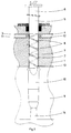
- the mixing head 1 is provided with a bore 2 in which end channels 3 and 4 for supply of the separate plastic components, which after mixing react with each other to form a polymerized product.
- the bore 2 accommodates a plunger 5, comprising a part 6 which fits closely in the bore 2 and a part 7 whose circumference is provided with helically running ribs 8.
- the plunger 5 can rotate in two directions and can be moved axially.
- the mixing head 1 is connected to a mould 9.
- the bore 2 of the mixing head 1 connects to the gate 10 of the mould 9.
- In the feed channels 3 and 4 for the plastic components there are axially movable valves 11 and 12 with which the feed openings to the bore or mixing chamber 2 can be opened and closed.
- the mixing head functions as follows: When the mixing starts the plunger 5 is in the position as shown in fig. 1. The plunger 5 rotates and the channels 3 and 4 for supply of the plastic components are opened. The valves 11 and 12 are in the retracted position. The plastic components are supplied into the mixing chamber 2 under pressure and are subjected to a return-pumping motion by the ribs 8 of plunger section 7. As the film layer formed is rubbed off and passes along the ribs 8, very intensive intermixing of the components takes place. In spite of the return-pumping motion by the ribs 8 the mass flow, owing to the supply under pressure of the components, moves to the free end of the plunger and via the gate 10 flows into the mould 9.
- the part 7 of the plunger 5 provided with ribs 8 is slightly tapered towards the free end. As a result, the thickness of the film layer 13 increases steadily, so that the pressure as well as the outflow speed decrease.
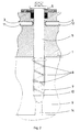
- the rotating plunger moves forward. Immediately after this movement the valves 11 and 12 are closed.
- the mixing device is then in the recirculation position.
- the mixture remaining in the mixing chamber is thereby entrained to the mould opening by the close-fitting part 6 of the plunger 5.
- the mixing chamber is thus cleansed. This position is shown in fig. 2.
- the rest of the mixture formed is injected into the mould.
- the apparatus and process according to the invention provide simply a fully self-cleansing mixing head for the mixing of chemically interreacting plastic components, with injection pressure independent mixing and pressure and speed decrease taking place in the mixing head.
- the turbulence occurring in the mixing head according to the invention is low, so that the mixture is injected with little turbulence into the mixing head. As a consequence, neither foaming nor air inclusion occurs when the mixing head is opened and during injection of the mixture into the mould.
Landscapes
- Engineering & Computer Science (AREA)
- Mechanical Engineering (AREA)
- Processing And Handling Of Plastics And Other Materials For Molding In General (AREA)
- Injection Moulding Of Plastics Or The Like (AREA)
Claims (6)
- Mischkopf zum Mischen von mindestens zwei flüssigen, chemisch interreagierenden, plastischen Komponenten, welcher Mischkopf ein Gehäuse, das mit einer Mischkammer versehen ist, die einen axial bewegbaren Plunger (5) enthält, mit zwei Kanälen (3, 4), die in der Mischkammer enden, um die plastischen Komponenten einzuspeisen, aufweist, welche Mischkammer mit einer Verbindung zu einer Form (9) versehen ist, in welcher Mischkammer sich der Plunger (5) drehen kann und worin der Plunger (5) über einen Teil seiner Länge in die Mischkammer eng eingepaßt ist, während der Umfang des restlichen Teils seiner Länge bis zum freien Ende des Plungers mit Mitteln zum Schermischen versehen ist, dadurch gekennzeichnet, daß sich der Plunger in zwei Richtungen drehen kann und daß als Mittel zum Schermischen schraubenförmig verlaufende Rippen (8) vorgesehen sind.
- Mischkopf nach Anspruch 1, dadurch gekennzeichnet, daß der gerippte Teil des Plungers mit einem kleinen Spielraum in die Mischkammer paßt.
- Mischkopf nach Anspruch 1 und 2, dadurch gekennzeichnet, daß der gerippte Teil des Plungers gegen das freie Ende leicht konisch verläuft.
- Mischkopf gemäß den Ansprüchen 1-3, dadurch gekennzeichnet, daß während des Mischens der plastischen Komponenten der gerippte Teil des sich drehenden Plungers (5) in der Mischkammer ist.
- Mischkopf nach den Ansprüchen 1-4, dadurch gekennzeichnet, daß der sich drehende Plunger (5) nach dem Mischen der plastischen Komponenten gegen den Einlauf (10) der Form bewegt wird.
- Verfahren zum Mischen von mindestens zwei chemisch interreagierenden, flüssigen, plastischen Komponenten unter Verwendung eines Mischkopfes nach einem oder mehreren der Ansprüche 1-5, worin während der Zuführung der plastischen Komponenten unter Druck der mit Mitteln zum Schermischen versehene Teil des Plungers (5) in der Mischkammer ist, während sich der Massenfluß der Komponenten zum freien Ende des Plungers (5) und über einen Einlauf (10) in die Form (9) bewegt, wonach der Plunger (5) nach dem Mischen axial gegen den Einlauf (10) bewegt und die Drehbewegung des Plungers (5) gestoppt wird, wobei die Mischkammer vom eng eingepaßten Teil des Plungers (5) gereinigt und der Rest des Gemisches in die Form (9) eingespritzt wird, wenn sich der Plunger (5) nach vor bewegt, wonach das Gemisch polymerisiert, dadurch gekennzeichnet, daß danach die entgegengesetzten Dreh- und Achsenbewegungen des Plungers (5) gestartet werden und sich der gerippte Teil des Plungers (5) aus dem polymerisierten Gemisch im Einlauf (10) herausdreht.
Applications Claiming Priority (2)
| Application Number | Priority Date | Filing Date | Title |
|---|---|---|---|
| NL9000889 | 1990-04-13 | ||
| NL9000889A NL9000889A (nl) | 1990-04-13 | 1990-04-13 | Mengkop voor het mengen van chemisch met elkaar reagerende vloeibare kunststofkomponenten. |
Publications (2)
| Publication Number | Publication Date |
|---|---|
| EP0451921A1 EP0451921A1 (de) | 1991-10-16 |
| EP0451921B1 true EP0451921B1 (de) | 1995-01-04 |
Family
ID=19856936
Family Applications (1)
| Application Number | Title | Priority Date | Filing Date |
|---|---|---|---|
| EP91200827A Expired - Lifetime EP0451921B1 (de) | 1990-04-13 | 1991-04-10 | Mischkopf zum Mischen flüssiger chemisch interreagierender plastischer Komponenten |
Country Status (3)
| Country | Link |
|---|---|
| EP (1) | EP0451921B1 (de) |
| DE (1) | DE69106420T2 (de) |
| NL (1) | NL9000889A (de) |
Cited By (6)
| Publication number | Priority date | Publication date | Assignee | Title |
|---|---|---|---|---|
| US7098179B2 (en) | 2001-10-22 | 2006-08-29 | Henkel Kommanditgesellschaft Auf Aktien (Henkel Kgaa) | Cotton active, dirt removing urethane-based polymers |
| US7316995B2 (en) | 2003-02-10 | 2008-01-08 | Henkel Kommanditgesellschaft Auf Aktien | Detergents or cleaning agents comprising a water-soluble building block system and a cellulose derivative with dirt dissolving properties |
| US7375072B2 (en) | 2003-02-10 | 2008-05-20 | Henkel Kommanditgesellschaft Auf Aktien | Bleach-containing laundry detergents or cleaning compositions comprising water-soluble builder system and soil release-capable cellulose derivative |
| US7431739B2 (en) | 2005-06-08 | 2008-10-07 | Henkel Kommanditgesellschaft Auf Aktien | Boosting the cleaning performance of laundry detergents by polymer of styrene/methyl methacrylate/methyl polyethylene glycol |
| KR20210141838A (ko) * | 2020-05-14 | 2021-11-23 | 조일공업주식회사 | 믹싱 헤드 |
| IT202400003406A1 (it) * | 2024-02-19 | 2025-08-19 | Astom S R L | Testa di iniezione di schiume polimeriche espansibili con controllo antigrippaggio |
Families Citing this family (5)
| Publication number | Priority date | Publication date | Assignee | Title |
|---|---|---|---|---|
| US5691295A (en) * | 1995-01-17 | 1997-11-25 | Cognis Gesellschaft Fuer Biotechnologie Mbh | Detergent compositions |
| DE19515039C2 (de) * | 1995-04-24 | 1998-10-01 | Krauss Maffei Ag | Vorrichtung zum Mischen von wenigstens zwei chemisch reaktiven Kunststoffkomponenten |
| FR2784929A1 (fr) * | 1998-09-11 | 2000-04-28 | Abel Belbati | Installation technique polyfonctionnelle pour le melange et la distribution des matieres plastiques thermodurcissables |
| JP4199102B2 (ja) | 2003-12-18 | 2008-12-17 | 東京エレクトロン株式会社 | 基板の処理方法,基板処理システム及び現像液供給ノズル |
| IT202000001168A1 (it) * | 2020-01-22 | 2021-07-22 | Persico Spa | Dispositivo e metodo di miscelazione |
Family Cites Families (7)
| Publication number | Priority date | Publication date | Assignee | Title |
|---|---|---|---|---|
| FR1215477A (fr) * | 1958-02-04 | 1960-04-19 | Degussa | Dispositif de dosage de mélange et d'application pour substances pâteuses |
| US3189325A (en) * | 1962-01-22 | 1965-06-15 | Levy Sidney | Mixing device |
| GB1154561A (en) * | 1965-03-10 | 1969-06-11 | Clarks Ltd | Improvements in or relating to the Manufacture of Plastic Articles. |
| DE2051109A1 (en) * | 1970-10-17 | 1972-04-20 | Nirona Werke Kg | Plastics mixing chamber cleaner - using pliable plug to scrape mixing tube and plug mould |
| DE2053684A1 (en) * | 1970-11-02 | 1972-05-10 | Baeumer Kg Spezialmasch | Plastics mixing unit - with single valve simultaneously operating both component inlets |
| US3843023A (en) * | 1973-09-17 | 1974-10-22 | D Vroom | Mixing and dispensing apparatus having nozzel cleaner |
| US3999740A (en) * | 1975-01-17 | 1976-12-28 | Mccorvey Raymond S | Mixing head |
-
1990
- 1990-04-13 NL NL9000889A patent/NL9000889A/nl not_active Application Discontinuation
-
1991
- 1991-04-10 DE DE69106420T patent/DE69106420T2/de not_active Expired - Fee Related
- 1991-04-10 EP EP91200827A patent/EP0451921B1/de not_active Expired - Lifetime
Cited By (7)
| Publication number | Priority date | Publication date | Assignee | Title |
|---|---|---|---|---|
| US7098179B2 (en) | 2001-10-22 | 2006-08-29 | Henkel Kommanditgesellschaft Auf Aktien (Henkel Kgaa) | Cotton active, dirt removing urethane-based polymers |
| US7316995B2 (en) | 2003-02-10 | 2008-01-08 | Henkel Kommanditgesellschaft Auf Aktien | Detergents or cleaning agents comprising a water-soluble building block system and a cellulose derivative with dirt dissolving properties |
| US7375072B2 (en) | 2003-02-10 | 2008-05-20 | Henkel Kommanditgesellschaft Auf Aktien | Bleach-containing laundry detergents or cleaning compositions comprising water-soluble builder system and soil release-capable cellulose derivative |
| US7431739B2 (en) | 2005-06-08 | 2008-10-07 | Henkel Kommanditgesellschaft Auf Aktien | Boosting the cleaning performance of laundry detergents by polymer of styrene/methyl methacrylate/methyl polyethylene glycol |
| KR20210141838A (ko) * | 2020-05-14 | 2021-11-23 | 조일공업주식회사 | 믹싱 헤드 |
| IT202400003406A1 (it) * | 2024-02-19 | 2025-08-19 | Astom S R L | Testa di iniezione di schiume polimeriche espansibili con controllo antigrippaggio |
| EP4603250A1 (de) * | 2024-02-19 | 2025-08-20 | Astom S.r.l. | Einspritzkopf für expanierbare polymerschäume mit anti-seize kontrolle |
Also Published As
| Publication number | Publication date |
|---|---|
| DE69106420D1 (de) | 1995-02-16 |
| NL9000889A (nl) | 1991-11-01 |
| DE69106420T2 (de) | 1995-05-04 |
| EP0451921A1 (de) | 1991-10-16 |
Similar Documents
| Publication | Publication Date | Title |
|---|---|---|
| US4275033A (en) | Apparatus for producing a reaction mixture containing fillers from at least two components which are capable of flowing | |
| EP0451921A1 (de) | Mischkopf zum Mischen flüssiger chemisch interreagierender plastischer Komponenten | |
| US3793416A (en) | Process for injection molding foam synthetic resin materials involving introduction of the expansion agent into the metering zone between injection molding steps | |
| US4397407A (en) | Apparatus for the production of a solid-forming or foam-forming mixture composed of at least two flowable reaction components and fillers | |
| US7169340B2 (en) | Resin and fiber compounding process for molding operations | |
| US6875385B2 (en) | Method of compounding resin and fiber | |
| US4749554A (en) | Nozzle for mixing flowable reaction components | |
| JPS6349412A (ja) | 少なくとも2つの反応し合うプラスチツク成分を混合するための装置及びこの装置を制御する方法 | |
| KR0184300B1 (ko) | 장섬유 보강 열가소성수지용 사출성형방법 및 사출성형장치 | |
| US5858416A (en) | Process and device for manufacturing plastic parts with reinforcement fibers | |
| US6431847B1 (en) | Apparatus for compounding resin and fiber | |
| US6065862A (en) | High-pressure mixing head | |
| US4680003A (en) | Apparatus for the production of moldings from flowable reactive components | |
| US6254813B1 (en) | Method and apparatus for injection molding plastic objects comprised of at least two different materials | |
| KR20060033017A (ko) | 성형방법, 퍼지방법 및 성형기 | |
| US3908966A (en) | Mixing apparatus | |
| US3709640A (en) | Means for the production of moulded components from chemical components whch react quickly with one another | |
| US4106113A (en) | Feeding screw assembly of a molding machine for plasticizing masses, particularly, for plastics or rubber | |
| JP3284233B2 (ja) | 射出成形機の可塑化装置 | |
| US3609817A (en) | Moulding apparatus for thermosetting plastics material | |
| KR20000071114A (ko) | 이소시아네이트 및 보다 고점성의 폴리올 배합물로부터 반응혼합물을 제조하기 위한 방법 및 혼합 헤드 | |
| JPH07276415A (ja) | 円弧形状中空品の射出成形方法 | |
| JP3202252B2 (ja) | 少なくとも2種の反応性プラスチック成分を混合する装置および方法 | |
| JPH0538738A (ja) | 可塑化部を分離したタイプの成形機 | |
| US5088909A (en) | Apparatus for extruding a marbleized synthetic-resin strand |
Legal Events
| Date | Code | Title | Description |
|---|---|---|---|
| PUAI | Public reference made under article 153(3) epc to a published international application that has entered the european phase |
Free format text: ORIGINAL CODE: 0009012 |
|
| AK | Designated contracting states |
Kind code of ref document: A1 Designated state(s): DE FR IT NL |
|
| 17P | Request for examination filed |
Effective date: 19920402 |
|
| 17Q | First examination report despatched |
Effective date: 19931006 |
|
| GRAA | (expected) grant |
Free format text: ORIGINAL CODE: 0009210 |
|
| AK | Designated contracting states |
Kind code of ref document: B1 Designated state(s): DE FR IT NL |
|
| PG25 | Lapsed in a contracting state [announced via postgrant information from national office to epo] |
Ref country code: IT Free format text: LAPSE BECAUSE OF FAILURE TO SUBMIT A TRANSLATION OF THE DESCRIPTION OR TO PAY THE FEE WITHIN THE PRE;WARNING: LAPSES OF ITALIAN PATENTS WITH EFFECTIVE DATE BEFORE 2007 MAY HAVE OCCURRED AT ANY TIME BEFORE 2007. THE CORRECT EFFECTIVE DATE MAY BE DIFFERENT FROM THE ONE RECORDED.SCRIBED TIME-LIMIT Effective date: 19950104 Ref country code: FR Effective date: 19950104 Ref country code: NL Effective date: 19950104 |
|
| REF | Corresponds to: |
Ref document number: 69106420 Country of ref document: DE Date of ref document: 19950216 |
|
| EN | Fr: translation not filed | ||
| NLV1 | Nl: lapsed or annulled due to failure to fulfill the requirements of art. 29p and 29m of the patents act | ||
| PLBE | No opposition filed within time limit |
Free format text: ORIGINAL CODE: 0009261 |
|
| STAA | Information on the status of an ep patent application or granted ep patent |
Free format text: STATUS: NO OPPOSITION FILED WITHIN TIME LIMIT |
|
| 26N | No opposition filed | ||
| PG25 | Lapsed in a contracting state [announced via postgrant information from national office to epo] |
Ref country code: DE Effective date: 19960103 |