EP0451960A2 - Empfängereinrichtung mit Schalt-Diversity - Google Patents
Empfängereinrichtung mit Schalt-Diversity Download PDFInfo
- Publication number
- EP0451960A2 EP0451960A2 EP91302119A EP91302119A EP0451960A2 EP 0451960 A2 EP0451960 A2 EP 0451960A2 EP 91302119 A EP91302119 A EP 91302119A EP 91302119 A EP91302119 A EP 91302119A EP 0451960 A2 EP0451960 A2 EP 0451960A2
- Authority
- EP
- European Patent Office
- Prior art keywords
- receiving
- signal
- output
- receiver
- systems
- Prior art date
- Legal status (The legal status is an assumption and is not a legal conclusion. Google has not performed a legal analysis and makes no representation as to the accuracy of the status listed.)
- Granted
Links
Images


Classifications
-
- H—ELECTRICITY
- H04—ELECTRIC COMMUNICATION TECHNIQUE
- H04B—TRANSMISSION
- H04B7/00—Radio transmission systems, i.e. using radiation field
- H04B7/02—Diversity systems; Multi-antenna system, i.e. transmission or reception using multiple antennas
- H04B7/04—Diversity systems; Multi-antenna system, i.e. transmission or reception using multiple antennas using two or more spaced independent antennas
- H04B7/08—Diversity systems; Multi-antenna system, i.e. transmission or reception using multiple antennas using two or more spaced independent antennas at the receiving station
- H04B7/0802—Diversity systems; Multi-antenna system, i.e. transmission or reception using multiple antennas using two or more spaced independent antennas at the receiving station using antenna selection
- H04B7/0817—Diversity systems; Multi-antenna system, i.e. transmission or reception using multiple antennas using two or more spaced independent antennas at the receiving station using antenna selection with multiple receivers and antenna path selection
- H04B7/082—Diversity systems; Multi-antenna system, i.e. transmission or reception using multiple antennas using two or more spaced independent antennas at the receiving station using antenna selection with multiple receivers and antenna path selection selecting best antenna path
Definitions
- This invention relates to a receiver, and more particularly to a radio receiver using a selective diversity receiving system.
- the diversity receiving system is well known.
- the diversity receiving system there are systems such as the selective diversity system, a switching diversity system, and the like. Explanation will now be given by taking an example of the selective diversity system.
- a plurality of receiving systems connected to respective antennas are sequentially selected by a selector to use, as a receiving signal, an output from a receiving system in the most satisfactory receiving state.
- the receiver roughly comprises two receiving systems, a selector for selecting any one of outputs from these two receiving systems, and a diversity controller for controlling the selector.
- Each receiving system comprises a receiving circuit connected to an antenna to process an RF (Radio Frequency) signal to output a received signal, and a receiving level detection circuit for detecting a receiving level signal (e.g., an S-meter level signal) corresponding to a field strength to output a receiving level signal.
- a receiving level signal e.g., an S-meter level signal
- the receiving circuit receives an RF signal from the antenna to output a received signal to the selector.
- the receiving level detection circuit detects a receiving level, e.g., from an output signal from circuits succeeding to a detector of the receiving circuit to output a detection signal to the diversity controller as a receiving level signal.
- the diversity controller outputs, to the selector, a selector control signal for selecting either of receiving systems on the basis of respective receiving level signals.
- the selector selects either of received output signals on the basis of the selector control signal to output a selected one as a selected received output signal.
- the selector outputs an output signal corresponding to a receiving system in the most satisfactory receiving state.
- the receiver selects a receiving system in a more satisfactory receiving state from these two receiving systems to maintain a satisfactory receiving state at all times.
- the above-mentioned diversity receiver has a problem that selection of the receiving system is not necessarily precisely conducted.
- the diversity controller generates a selector control signal either on the basis of a receiving level signal, or on the basis of a noise level signal, and both the received signal and the noise level are not considered at the same time.
- a selector control signal either on the basis of a receiving level signal, or on the basis of a noise level signal, and both the received signal and the noise level are not considered at the same time.
- an object of this invention is to provide a receiver capable of easily and stably selecting a receiving system in the most satisfactory receiving state.
- a receiver comprising a plurality of receiving systems connected to a plurality of antennas, respectively, and a selective switching circuit for carrying out selective switching between output signals from the plurality of receiving systems to output an output signal from a receiving system in the most satisfactory receiving state
- the selective switching circuit comprises discrimination means for respectively discriminating receiving states of the receiving systems by a fuzzy inference operation on the basis of received signals from the receiving systems to compare with each other discriminated results with respect to the respective receiving systems to output a select signal in the most satisfactory receiving system.
- a plurality of antennas process an input signal from the antennas, respectively, to output a received signal.
- a discrimination means discriminates receiving states of respective receiving system by a fuzzy inference operation on the basis of received signals from the respective receiving systems to compare with each other discriminated results with respect to respective receiving systems, thus to a select signal in the most satisfactory receiving system.
- Select means switches and outputs received signal in the most satisfactory receiving system on the basis of the select signal.
- selective switching circuit can select receiving system in consideration of the operating characteristic with respect to each of the receiving system. Accordingly, switching operation is carried out accurately.
- the diversity receiving system includes a selective diversity system.
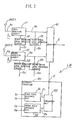
- the receiver comprises a first and a second receiving systems R1, R2, a selector 300 for selecting any one of outputs from these two receiving systems R1, R2 and a diversity controller 400 for controlling the selector 300.
- the first receiving system R1 comprises a first receiving circuit 100 connected to an antenna ANT1 to process an RF (Radio Frequency) signal A1 to output a received signal B1, a first receiving level detection circuit 102 for detecting a receiving level signal (e.g., an S-meter level signal) corresponding to a field strength to output a first receiving level signal, and a first noise level detection circuit 103 for detecting a signal level of a noise included in the received output signal B1 to output a first noise level signal.
- the first receiving circuit 100 is composed of a front end (not shown), an intermediate frequency amplifier, and a detector, etc.
- the first level detection circuit 102 detects a receiving level signal S1, e.g., from an output signal extracted from circuits succeeding to the intermediate frequency amplifier or detector.
- the first noise level detection circuit 103 is composed of, e.g., a high-pass filter (not shown) to detect a noise level from an output signal level of the high-pass filter.
- the second receiving system R2 includes, in the same manner as in the first receiving system R1, a second receiving circuit 200, a second receiving level detection circuit 202, and a second noise level detection circuit 203. Further, in the second receiving system R2, a gain controller for controlling or adjusting a difference between the operating characteristic of the second receiving system R2 and that of the first receiving system R1 is provided in the second receiving circuit 200. For example, a volume for gain control is provided at the output terminal of a front end (not shown).
- the diversity controller 400 outputs, to a selector 300, a selector control signal E for selecting any one of the first and second receiving systems on the basis of a receiving level signal and a noise level signal of the first or second receiving system R1 or R2.
- the selector 300 outputs, as a selected received output signal D, the above-mentioned output signal provided by applying switching selection to output signals from the first and second receiving systems R1, R2 on the basis of a selector control signal E from the diversity controller 400.
- the first receiving circuit 100 receives an RF signal A1 from the antenna ANT1 connected thereto to output a received signal B1.
- the first receiving level detection circuit 102 detects a receiving level, e.g., from ,an output signal from circuits succeeding to a detector (not shown) of the first receiving circuit 100 to output a first receiving level signal S1.
- the first noise level detection circuit 103 detects a noise signal level included in the received output signal B1 to output it as a first noise level signal N1 to the diversity controller 400.
- a second receiving level signal S2 is outputted from the second receiving level detection circuit 202, to the diversity controller 400, and a second noise level signal N2 is outputted from the second noise level detection circuit 103 to the diversity controller 400.
- the diversity controller 400 outputs, to the selector 300, a selector control signal E for selecting any one of receiving systems on the basis of respective receiving level signals S1 and S2, or respective noise level signals N1 and N2.
- the selector 300 outputs a selected signal on the basis of either the receiving level signals (S-meter level) S1, S2 or noise level signals N1, N2.
- the selection operation of the selector 300 is not carried out in consideration of the both factors of the S-meter level and the noise level at the same time. Therefore, there are cases that even if the S-meter level is sufficiently high, the noise level is very high, and that even if the noise level is low, the S-meter level is also low. In this manner, a convention receiver cannot necessarily maintain a satisfactory receiving state at all times.
- a receiver 1 of this invention comprises a pluality of receiving systems 2-1, 2-2, ⁇ 2-n connected to a plurality of antennas ANT1 - ANTn, respectively, and a selective switching circuit 5 for carrying out selective switching between output signals from said plurality of receiving systems 2-1, 2-2, ⁇ 2-n to output an output signal of a receiving system in the most satisfactory receiving state.
- the selective switching circuit 5 comprises discrimination means 3 for discriminating receiving states of respective receiving systems by a fuzzy inference operation on the basis of received signals from the respective receiving systems to compare with each other discriminated results with respect to said respective receiving systems, thus to output a select signal in the most satisfactory receiving system.
- FIG. 2 shows a case where two receiving systems are provided.
- a receiver 10 roughly comprises a first receiving system R1 connected to an antenna ANT1, a second receiving system R2 connected to an antenna ANT2, a selector 41 for selecting any one of the first and second receiving systems R1, R2 and a diversity controller 30 for controlling the selector 41.
- the first receiving system R1 comprises a first receiving circuit 11 for processing an RF signal A1 from the antenna ANT1 to output a received signal B1, a first receiving level detection circuit 12 for detecting a receiving level signal (e.g., S-meter level signal) corresponding to a field strength to output a first receiving level signal S1, and a first noise level detection circuit 13 for detecting a signal level of noise included in the received output signal B1 to output a first noise level signal N1.
- the receiving circuit 11 comprises a front end (not shown), an intermediate frequency amplifier, and a detector, etc.
- the first level detection circuit 12 serves to detect a receiving level signal S1, e.g., an output signal from circuits succeeding to the intermediate amplifier or the detector.
- the second receiving system R2 comprises, in the same manner as in the first receiving system R1, a second receiving circuit 21, a second receiving level detection circuit 22 for outputting a second receiving level signal S2, and a second noise level detection circuit 23 for outputting a second noise level signal N2 on the basis of noise included in the received output signal B2.
- the diversity controller 30 includes a CPU and a memory to perform a fuzzy inference operation by a program and a membership function included therein. More particularly, this controller 30 comprises a fuzzy inference operation on the basis of the first receiving level signal S1 and the first noise level signal N1 to output a first fuzzy inference result signal F1, and a second fuzzy inference section 32 for performing a fuzzy inference operation on the basis of the second receiving level signal S2 and the second noise level signal N2 to output a second fuzzy inference result signal F2.
- the controller 30 further comprises a comparison unit 33 adapted to output a selector control signal E for selecting any one of the first and second receiving systems R1, R2 on the basis of the first and second fuzzy inference result signals F1 and F2.
- the comparison unit 33 is composed of, e.g., a comparator.
- the selector 41 carries out switching between received signals B1 and B2 on the basis of the selector control signal E to output a selected one as a received output signal C.
- the first receiving circuit 11 processes an RF signal A1 from the antenna ANT1 to output a received signal B1.
- the first receiving level detection circuit 12 detects a receiving level, e.g., from an output signal extracted from circuits succeeding to a detector (not shown) of the first receiving circuit 11 to output a first receiving level detection signal S1.
- the first noise level detection circuit 13 detects the level of a noise signal included in the received signal B1 to output a first noise level detection signal N1.
- the second receiving circuit 21 processes an RF signal A1 inputted from the antenna ANT2 to output a received signal B2.
- the second receiving level detection circuit 22 detects a receiving level, e.g., from an output signal from circuits succeeding to a detector (not shown) of the second receiving system R2 to output a second receiving level signal S2.
- the second noise level detection circuit 23 detects the level of a noise signal included in the received signal B2 to output a second noise level detection signal N2.
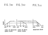
- the first fuzzy inference unit 31 outputs a first fuzzy inference result signal F1 on the basis of a membership function set in advance by using the first receiving level signal S1 and the first noise level signal N1. More practically, the grade of the first receiving level signal S1 is first determined from the membership function (Fig. 3(a)) showing the level of the first receiving level signal S1. Then, the grade of the first noise level signal is determined on the basis of the membership function (Fig. 3(b)) showing the level of the first noise level signal N1. Further, the grade of the receiving state is determined by Mini-max method, etc. on the basis of the grades of these respective signal levels (Fig.
- the second fuzzy inference unit 32 outputs a second fuzzy inference result signal on the basis of a membership function set in advance by using the second receiving level signal S2 and the second noise level signal N2.
- the comparison unit 33 outputs a selector control signal E for selecting the first or second receiving system in a more satisfactory receiving state on the basis of those fuzzy inference result signals F1 and F2.
- the first selector 41 selectively outputs, as a received output signal C, a received signal in any one of the receiving systems R1, R2 on the basis of the selector control signal E.
- the receiving condition is determined to be in an intermediate state (condition C1) by selecting the lower grade with respect to a membership function of FIG. 3(c). Further, suppose that the level of the signal S2 is relatively low (level l3) and that the level of the noise signal N2 is relatively high, the receiving condition is determined to be relatively good (condition C2). Then, the two conditions C1, C2 are compared with each other through the comparison unit 33 to select the second receiving system R2.
- an approach is employed to carry out the fuzzy inference on the basis of the receiving level signals and the noise level signals of the respective receiving systems to compare fuzzy inference results of the respective receiving systems with each other thereby to make a selection of the receiving systems.
- the optimum receiving system can be easily selected without setting in advance a rigorous condition for the optimum receiving state.
- FIG. 4 shows a receiver 70 having two receiving systems R1, R2.
- the same reference numerals are attached to the same portions as those of the first embodiment, respectively, and their explanation will be conducted.
- the second embodiment differs from the first embodiment in that the comparison unit 33 has a hysteresis characteristic in order that switching of the receiving system is not frequently carried out when the receiving level signal suddenly changes, and that there is provided in the comparison unit 33 a hysteresis characteristic alteration section 34 having a function to alter the hysteresis characteristic on the basis of a receiving level signal.
- the comparison unit 33 provided with the hysterisis characteristic alteration section 34 comprises, as shown in FIG. 5(a), a Schmitt circuit 36 including an operational amplifier 35, two input resistors R1 and R2, and a group of feedback resistors R3 which can be switched, a switching instructing section 37 adapted to output a switching instruction signal G for carrying out selective switching between feedback resistors R3 on the basis of a receiving level signal corresponding to a receiving system selected on the basis of the selector control signal E, and a changeover switch 38 or carrying out selective switching between feedback resistors R 3a , R 3b , R 3c on the basis of the switching instruction signal G.
- the first receiving circuit 11 processes an RF signal A1 inputted from the antenna ANT1 to output a signal such as a received signal B1, etc.
- the first receiving level detection circuit 12 detects a receiving level from an inputted signal to output a first receiving level detection signal S1.
- the first noise level detection circuit 13 detects the level of a noise signal included in the received signal B1 to output a first noise level detection signal N1.
- the second receiving circuit 21 processes an RF signal inputted from the antenna ANT2 to output a received signal B2.
- the second receiving level detection circuit 22 detects a receiving level from an inputted signal to output a second receiving level signal S2.
- the second noise level detection circuit 23 detects the level of a noise signal included in the received signal B2 to output a second noise level detection signal N2.
- first and second receiving level signals S1 and S2 and first and second noise level signals N1 and N2 are inputted.
- the first fuzzy inference unit 31 outputs a first fuzzy inference result signal F1 on the basis of a membership function set in advance by using the first receiving level signal S1 and the first noise level signal N1.
- the second fuzzy inference unit 32 outputs a second fuzzy inference result signal F2 on the basis of a membership function set in advance by using the second receiving level signal S2 and the second noise level signal N2.
- the switching instructing unit 37 outputs a switching instruction signal G for carrying out selective switching between feedback resistors R3 on the basis of a receiving level signal corresponding to the selector control signal E.
- V H R2/(R2 + R3) ⁇ (V1 - V2) where V1 is a power supply voltage on the plus side and V2 is a power supply voltage on the minus side.
- the selector 41 selectively outputs a received signal in any one of receiving systems R1, R2 as a received output signal C on the basis of a selector control signal E.
- switching between feedback resistors of the Schmitt circuit 36 is carried out on the basis of one receiving level signal
- this switching is carried out by using a mean value of respective receiving level signals S1, S2.
- weighting is applied to respective receiving level signals to use a mean value of the weighted signals.
- switching between feedback resistors is carried out stepwise, such a switching is continuously carried out.
- the receiving states of respective receiving systems are determined by the fuzzy inference operation, it is possible to synthetically judge the receiving state without making in advance setting of a rigorous condition for selection of the optimum receiving system to select the optimum receiving system with ease and stably.
- FIG. 6 shows a case where two systems R1, R2 are provided in a receiver 80.
- the same reference numerals as those of the first embodiment are attached to portions which can carry out the same function and operation as those of the first embodiment, respectively, and explanation will be conducted.
- the receiver 80 roughly comprises a first receiving system R1 connected to the antenna ANT1, a second receiving system R1 connected to the antenna ANT2, a selector 40 for selecting any one of outputs from the first and second receiving systems R1, R2 and a diversity controller 30 for controlling the selector 41.
- the first receiving system R1 comprises a first receiving circuit 11 for processing an RF signal A1 from the antenna ANT1 to output a received signal B1, a first receiving level detection circuit 12 for detecting a receiving level signal (e.g., S-meter level signal) corresponding to a field strength to output a first receiving level signal S1, and a first noise level detection circuit 13 for detecting a signal level of noise included in the received output signal B1 to output a first noise level signal N1.
- the first receiving circuit 11 comprises a front end (not shown), an intermediate frequency amplifier, and a detector, etc.
- the first receiving level detection circuit 12 detects a receiving level signal S1, e.g., from an output signal from circuits succeeding to the intermediate frequency amplifier or the detector.
- the first noise level detection circuit 13 is composed of, e.g., a high-pass filter (not shown) to detect the noise level by the output signal level of the high-pass filter.
- the second receiving system R2 includes, in the same manner as in the first receiving system R1, a second receiving circuit 21, a second receiving level detection circuit 22 for outputting a second receiving level signal S2, and a second noise level detection circuit 23 for outputting a second receiving level signal N2.
- the diversity controller 30 comprises a fuzzy inference unit 51 including a CPU to discriminate the receiving states of respective receiving systems by the fuzzy inference on the basis of the receiving level signal S1 or S2, and the noise level signals N1 and N2 of the first or second receiving system R1 or R2 in accordance with a program included to output a selector control signal E for selecting any one of the first and second receiving systems R1, R2.
- a fuzzy inference unit 51 including a CPU to discriminate the receiving states of respective receiving systems by the fuzzy inference on the basis of the receiving level signal S1 or S2, and the noise level signals N1 and N2 of the first or second receiving system R1 or R2 in accordance with a program included to output a selector control signal E for selecting any one of the first and second receiving systems R1, R2.
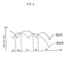
- the fuzzy inference unit 51 comprises a membership function alteration section 52 for altering the membership function with respect to each of receiving systems R1, R2 on the basis of unevenness of the operating characteristics of the respective receiving systems R1, R2.
- This membership function alteration section 52 serves to provide the optimum membership function in correspondence with the operating characteristics of the respective receiving systems.
- the membership function alteration section 52 functions as follows.
- the membership function alteration section 52 serves to shift, as shown in FIG. 7(b), a membership function with respect to the level of a receiving level signal applied to the second receiving level signal S2 (the solid line indicates the shifted membership function).
- the second receiving level signal S2 from the second receiving circuit 21 is not subjected to influence by unevenness of the operating characteristic. As a result, the receiving state can be precisely discriminated.
- the first receiving circuit 11 process an RF signal A1 from the antenna ANT1 to output a received signal B1.
- the first receiving level detection circuit 12 detects a receiving level, e.g., from an output signal from circuits succeeding to a detector (not shown) of the first receiving circuit 11 to output a first receiving level signal S1.
- the first noise level detection circuit 13 detects the level of a noise signal included in the received signal B1 to output a first noise level signal N1.
- the second receiving circuit 21 processes an RF signal A1 inputted from the antenna ANT2 to output a received signal B2.
- the second receiving level detection circuit 22 detects the receiving level, e.g., from an output signal from the state succeeding to a detector (not shown) of the second receiving circuit to output a second receiving level signal S2.
- the second noise level detection circuit 23 detects the level of a noise signal included in the received signal B2 to output a second noise level signal N2.
- the fuzzy inference unit 51 performs a fuzzy inference by using membership functions altered with respect to each of receiving systems R1, R2 to output a selector control signal E for selecting any one of first and second receiving systems R1, R2 in a more satisfactory receiving state. Therefore, it is not necessary to provide a gain controller of the front end of a system.
- the selector 41 selectively receives a received signal of either the receiving system R1 or R2 on the basis of the selector control signal E to output a selected one as the output signal C.
- the fuzzy inference unit for discriminating states of respective receiving systems by the fuzzy inference is provided in the selective switching circuit.
- a membership function alteration section having a function to alter the membership function with respect to each of the systems is provided.
Landscapes
- Engineering & Computer Science (AREA)
- Computer Networks & Wireless Communication (AREA)
- Signal Processing (AREA)
- Radio Transmission System (AREA)
Applications Claiming Priority (4)
| Application Number | Priority Date | Filing Date | Title |
|---|---|---|---|
| JP2063315A JP3007373B2 (ja) | 1990-03-14 | 1990-03-14 | 受信機 |
| JP63313/90 | 1990-03-14 | ||
| JP63315/90 | 1990-03-14 | ||
| JP2063313A JPH03265227A (ja) | 1990-03-14 | 1990-03-14 | 受信機 |
Publications (3)
| Publication Number | Publication Date |
|---|---|
| EP0451960A2 true EP0451960A2 (de) | 1991-10-16 |
| EP0451960A3 EP0451960A3 (en) | 1992-11-25 |
| EP0451960B1 EP0451960B1 (de) | 1996-12-11 |
Family
ID=26404407
Family Applications (1)
| Application Number | Title | Priority Date | Filing Date |
|---|---|---|---|
| EP91302119A Expired - Lifetime EP0451960B1 (de) | 1990-03-14 | 1991-03-13 | Empfängereinrichtung mit Schalt-Diversity |
Country Status (4)
| Country | Link |
|---|---|
| US (1) | US5390342A (de) |
| EP (1) | EP0451960B1 (de) |
| CA (1) | CA2038278A1 (de) |
| DE (1) | DE69123480D1 (de) |
Cited By (3)
| Publication number | Priority date | Publication date | Assignee | Title |
|---|---|---|---|---|
| WO1998004054A1 (en) * | 1996-07-18 | 1998-01-29 | Ericsson Inc. | System and method for reducing cumulative noise in a distributed antenna network |
| EP1033826A3 (de) * | 1999-03-01 | 2003-07-23 | Ford Motor Company | Proportionaler Funk-Diversity-Empfänger mit dinamischen geregelten Geräuschen Antennenphaser |
| GB2384651A (en) * | 2002-01-28 | 2003-07-30 | Toshiba Res Europ Ltd | Signal selection systems |
Families Citing this family (32)
| Publication number | Priority date | Publication date | Assignee | Title |
|---|---|---|---|---|
| US5481571A (en) * | 1993-11-12 | 1996-01-02 | Pacific Communication Sciences, Inc. | Method and apparatus for switching between radio frequency circuits |
| US5541963A (en) * | 1993-12-01 | 1996-07-30 | Hitachi, Ltd. | Diversity receiving apparatus |
| US5819182A (en) * | 1995-11-13 | 1998-10-06 | Pacific Communication Sciences, Inc. | Method and apparatus for improving receiver performance in a land mobile communications system |
| US5940452A (en) * | 1995-11-29 | 1999-08-17 | Motorola, Inc. | Dual mode radio subscriber unit having a diversity receiver apparatus and method therefor |
| US6421543B1 (en) * | 1996-01-29 | 2002-07-16 | Ericsson Inc. | Cellular radiotelephone base stations and methods using selected multiple diversity reception |
| JP3060952B2 (ja) * | 1996-07-19 | 2000-07-10 | 日本電気株式会社 | ダイバーシチ受信装置 |
| DE19630722C2 (de) * | 1996-07-30 | 1998-06-04 | Aerodata Flugmestechnik Gmbh | Satellitennavigationsempfangsgerät |
| US6085076A (en) * | 1997-04-07 | 2000-07-04 | Omnipoint Corporation | Antenna diversity for wireless communication system |
| DE19743123B4 (de) * | 1997-09-30 | 2005-11-24 | Harman Becker Automotive Systems (Xsys Division) Gmbh | Verfahren und Schaltungsanordnung zur Auswahl eines von mehreren Empfängern einer Diversity-Empfangsanlage |
| US6115930A (en) * | 1998-06-11 | 2000-09-12 | Fuji Photo Film Co., Ltd. | Method and laminated member for measuring gap dimension |
| DE19845534B4 (de) * | 1998-10-02 | 2005-01-27 | Robert Bosch Gmbh | Antennenschaltung |
| US6308054B2 (en) * | 1999-03-02 | 2001-10-23 | Hitachi, Ltd. | Diversity wireless communication method and its wireless communication apparatus |
| JP3629261B2 (ja) * | 2002-11-26 | 2005-03-16 | 松下電器産業株式会社 | 無線受信装置 |
| US9026070B2 (en) * | 2003-12-18 | 2015-05-05 | Qualcomm Incorporated | Low-power wireless diversity receiver with multiple receive paths |
| US20060276149A1 (en) * | 2005-06-03 | 2006-12-07 | Microtune (Texas), L.P. | Multi-band broadcast tuner |
| US9450665B2 (en) * | 2005-10-19 | 2016-09-20 | Qualcomm Incorporated | Diversity receiver for wireless communication |
| KR100786112B1 (ko) * | 2007-07-09 | 2007-12-18 | 장애인표준사업장비클시스템 주식회사 | 차량용 수신기의 통합 연결장치 |
| US9178669B2 (en) | 2011-05-17 | 2015-11-03 | Qualcomm Incorporated | Non-adjacent carrier aggregation architecture |
| US9252827B2 (en) | 2011-06-27 | 2016-02-02 | Qualcomm Incorporated | Signal splitting carrier aggregation receiver architecture |
| US9154179B2 (en) | 2011-06-29 | 2015-10-06 | Qualcomm Incorporated | Receiver with bypass mode for improved sensitivity |
| US12081243B2 (en) | 2011-08-16 | 2024-09-03 | Qualcomm Incorporated | Low noise amplifiers with combined outputs |
| US8774334B2 (en) | 2011-11-09 | 2014-07-08 | Qualcomm Incorporated | Dynamic receiver switching |
| US9362958B2 (en) | 2012-03-02 | 2016-06-07 | Qualcomm Incorporated | Single chip signal splitting carrier aggregation receiver architecture |
| US9172402B2 (en) | 2012-03-02 | 2015-10-27 | Qualcomm Incorporated | Multiple-input and multiple-output carrier aggregation receiver reuse architecture |
| US9118439B2 (en) | 2012-04-06 | 2015-08-25 | Qualcomm Incorporated | Receiver for imbalanced carriers |
| US9154356B2 (en) | 2012-05-25 | 2015-10-06 | Qualcomm Incorporated | Low noise amplifiers for carrier aggregation |
| US9867194B2 (en) | 2012-06-12 | 2018-01-09 | Qualcomm Incorporated | Dynamic UE scheduling with shared antenna and carrier aggregation |
| US9300420B2 (en) | 2012-09-11 | 2016-03-29 | Qualcomm Incorporated | Carrier aggregation receiver architecture |
| US9543903B2 (en) | 2012-10-22 | 2017-01-10 | Qualcomm Incorporated | Amplifiers with noise splitting |
| US20140179235A1 (en) * | 2012-12-20 | 2014-06-26 | Mediatek Inc. | Method for reducing power consumption and communications apparatus utilizing the same |
| US8995591B2 (en) | 2013-03-14 | 2015-03-31 | Qualcomm, Incorporated | Reusing a single-chip carrier aggregation receiver to support non-cellular diversity |
| US10177722B2 (en) | 2016-01-12 | 2019-01-08 | Qualcomm Incorporated | Carrier aggregation low-noise amplifier with tunable integrated power splitter |
Family Cites Families (6)
| Publication number | Priority date | Publication date | Assignee | Title |
|---|---|---|---|---|
| JPS5428669A (en) * | 1977-08-08 | 1979-03-03 | Nec Corp | Noise measuring circuit |
| JPH0683127B2 (ja) * | 1985-07-22 | 1994-10-19 | 日本電気株式会社 | ダイバーシチ受信無線機 |
| DE3612235A1 (de) * | 1986-04-11 | 1987-10-15 | Blaupunkt Werke Gmbh | Verfahren und schaltungsanordnung zum empfang von radiowellen mit mehreren antennen |
| JP2708777B2 (ja) * | 1988-05-19 | 1998-02-04 | 三洋電機株式会社 | ダイバーシティ受信装置 |
| JPH03259622A (ja) * | 1990-03-09 | 1991-11-19 | Pioneer Electron Corp | ノイズ低減回路 |
| EP0449199B1 (de) * | 1990-03-28 | 1995-07-05 | Pioneer Electronic Corporation | Rauschreduktionsschaltung |
-
1991
- 1991-03-12 US US07/667,931 patent/US5390342A/en not_active Expired - Fee Related
- 1991-03-13 EP EP91302119A patent/EP0451960B1/de not_active Expired - Lifetime
- 1991-03-13 DE DE69123480T patent/DE69123480D1/de not_active Expired - Lifetime
- 1991-03-14 CA CA002038278A patent/CA2038278A1/en not_active Abandoned
Cited By (4)
| Publication number | Priority date | Publication date | Assignee | Title |
|---|---|---|---|---|
| WO1998004054A1 (en) * | 1996-07-18 | 1998-01-29 | Ericsson Inc. | System and method for reducing cumulative noise in a distributed antenna network |
| EP1033826A3 (de) * | 1999-03-01 | 2003-07-23 | Ford Motor Company | Proportionaler Funk-Diversity-Empfänger mit dinamischen geregelten Geräuschen Antennenphaser |
| GB2384651A (en) * | 2002-01-28 | 2003-07-30 | Toshiba Res Europ Ltd | Signal selection systems |
| GB2384651B (en) * | 2002-01-28 | 2004-03-24 | Toshiba Res Europ Ltd | Signal selection systems |
Also Published As
| Publication number | Publication date |
|---|---|
| EP0451960B1 (de) | 1996-12-11 |
| CA2038278A1 (en) | 1991-09-15 |
| US5390342A (en) | 1995-02-14 |
| EP0451960A3 (en) | 1992-11-25 |
| DE69123480D1 (de) | 1997-01-23 |
Similar Documents
| Publication | Publication Date | Title |
|---|---|---|
| EP0451960A2 (de) | Empfängereinrichtung mit Schalt-Diversity | |
| US6045042A (en) | Non-contact IC card having multiple receivers with different signal detection threshholds for minimizing current consumption | |
| US4035728A (en) | Diversity receiving system | |
| US4823398A (en) | Diversity receiver | |
| US5566364A (en) | Power saving portable radio communication device with diversity reception | |
| US6636729B1 (en) | Apparatus and method for receiving radio signals according to variable weighting factors | |
| KR860009599A (ko) | 안테나 다이버시티 시스템 | |
| US4598426A (en) | Variable intermediate bandwidth AM receiver | |
| US5886545A (en) | Priority switching apparatus of input signal | |
| EP0138693A1 (de) | Verfahren und Gerät zur Überwachung einer digitalen Radioübertragungsleitung | |
| EP0499800B1 (de) | Komparator für Raumdiversityempfänger | |
| JPH0715380A (ja) | 復調方式選択受信ダイバーシチ回路 | |
| GB2237479A (en) | Non-contact IC card has receivers with different thresholds | |
| US5436582A (en) | Comparator device for selecting received signals | |
| KR100638505B1 (ko) | 스위칭 다이버시티 시스템의 테스트를 위한 회로장치 및 방법 | |
| JPH03265227A (ja) | 受信機 | |
| US20040198341A1 (en) | RF detection and switching system and method | |
| JPS60140934A (ja) | ダイバシテイ受信機 | |
| JPH0888593A (ja) | ダイバーシティ受信切換方式 | |
| SU1128395A1 (ru) | Устройство адаптивного приема сигнала | |
| EP4087054A1 (de) | Kommunikationsvorrichtung für ein fahrzeug und steuerverfahren dafür | |
| JP3007373B2 (ja) | 受信機 | |
| JP2000115042A (ja) | ダイバシティ受信装置 | |
| JPH02122730A (ja) | 信号ライン終端方式 | |
| JPH08163016A (ja) | ダイバシティ受信装置 |
Legal Events
| Date | Code | Title | Description |
|---|---|---|---|
| PUAI | Public reference made under article 153(3) epc to a published international application that has entered the european phase |
Free format text: ORIGINAL CODE: 0009012 |
|
| AK | Designated contracting states |
Kind code of ref document: A2 Designated state(s): DE FR GB |
|
| PUAL | Search report despatched |
Free format text: ORIGINAL CODE: 0009013 |
|
| AK | Designated contracting states |
Kind code of ref document: A3 Designated state(s): DE FR GB |
|
| 17P | Request for examination filed |
Effective date: 19930507 |
|
| 17Q | First examination report despatched |
Effective date: 19950619 |
|
| GRAG | Despatch of communication of intention to grant |
Free format text: ORIGINAL CODE: EPIDOS AGRA |
|
| GRAH | Despatch of communication of intention to grant a patent |
Free format text: ORIGINAL CODE: EPIDOS IGRA |
|
| GRAH | Despatch of communication of intention to grant a patent |
Free format text: ORIGINAL CODE: EPIDOS IGRA |
|
| GRAA | (expected) grant |
Free format text: ORIGINAL CODE: 0009210 |
|
| AK | Designated contracting states |
Kind code of ref document: B1 Designated state(s): DE FR GB |
|
| PG25 | Lapsed in a contracting state [announced via postgrant information from national office to epo] |
Ref country code: FR Effective date: 19961211 |
|
| REF | Corresponds to: |
Ref document number: 69123480 Country of ref document: DE Date of ref document: 19970123 |
|
| PG25 | Lapsed in a contracting state [announced via postgrant information from national office to epo] |
Ref country code: DE Effective date: 19970312 |
|
| PG25 | Lapsed in a contracting state [announced via postgrant information from national office to epo] |
Ref country code: GB Effective date: 19970313 |
|
| EN | Fr: translation not filed | ||
| PLBE | No opposition filed within time limit |
Free format text: ORIGINAL CODE: 0009261 |
|
| STAA | Information on the status of an ep patent application or granted ep patent |
Free format text: STATUS: NO OPPOSITION FILED WITHIN TIME LIMIT |
|
| GBPC | Gb: european patent ceased through non-payment of renewal fee |
Effective date: 19970313 |
|
| 26N | No opposition filed |