EP0451974B1 - C-, S- und T-Schalter, betätigt von Permanentmagneten - Google Patents
C-, S- und T-Schalter, betätigt von Permanentmagneten Download PDFInfo
- Publication number
- EP0451974B1 EP0451974B1 EP91302471A EP91302471A EP0451974B1 EP 0451974 B1 EP0451974 B1 EP 0451974B1 EP 91302471 A EP91302471 A EP 91302471A EP 91302471 A EP91302471 A EP 91302471A EP 0451974 B1 EP0451974 B1 EP 0451974B1
- Authority
- EP
- European Patent Office
- Prior art keywords
- connector
- magnets
- actuator
- magnet
- switch
- Prior art date
- Legal status (The legal status is an assumption and is not a legal conclusion. Google has not performed a legal analysis and makes no representation as to the accuracy of the status listed.)
- Expired - Lifetime
Links
- 239000004020 conductor Substances 0.000 claims description 45
- 235000014676 Phragmites communis Nutrition 0.000 description 47
- 238000004804 winding Methods 0.000 description 5
- XEEYBQQBJWHFJM-UHFFFAOYSA-N Iron Chemical compound [Fe] XEEYBQQBJWHFJM-UHFFFAOYSA-N 0.000 description 2
- 239000000463 material Substances 0.000 description 2
- 244000089486 Phragmites australis subsp australis Species 0.000 description 1
- 230000004913 activation Effects 0.000 description 1
- 230000009286 beneficial effect Effects 0.000 description 1
- 229910052742 iron Inorganic materials 0.000 description 1
- 230000007257 malfunction Effects 0.000 description 1
- 238000004519 manufacturing process Methods 0.000 description 1
- 230000001846 repelling effect Effects 0.000 description 1
Images


Classifications
-
- H—ELECTRICITY
- H01—ELECTRIC ELEMENTS
- H01P—WAVEGUIDES; RESONATORS, LINES, OR OTHER DEVICES OF THE WAVEGUIDE TYPE
- H01P1/00—Auxiliary devices
- H01P1/10—Auxiliary devices for switching or interrupting
- H01P1/12—Auxiliary devices for switching or interrupting by mechanical chopper
- H01P1/125—Coaxial switches
-
- H—ELECTRICITY
- H01—ELECTRIC ELEMENTS
- H01H—ELECTRIC SWITCHES; RELAYS; SELECTORS; EMERGENCY PROTECTIVE DEVICES
- H01H36/00—Switches actuated by change of magnetic field or of electric field, e.g. by change of relative position of magnet and switch, by shielding
- H01H36/0073—Switches actuated by change of magnetic field or of electric field, e.g. by change of relative position of magnet and switch, by shielding actuated by relative movement between two magnets
Definitions
- This invention relates to a microwave switch and, in particular, to a transfer switch that is an S-switch, a C-switch, a T-switch or the like and is operated by permanent magnets.
- Transfer switches such as C-switches, S-switches or T-switches are known and are widely used in the space communciations industry.
- a communications satellite will contain numerous coaxial C-switches, S-switches or T-switches.
- Previous switches have a larger mass and a much larger volume than switches of the present invention. Further, previous switches are more complex and expensive to manufacture and some previous switches have a relatively large number of moving parts making them more susceptible to failure. In previous switches, an interior of the RF cavity is always open to the actuator resulting in leakage of electromagnetic energy from the cavity.
- the switch of the present application is an improvement over the switch described in U.S. Patent #4,851,801, entitled "Microwave C-switches and S-switches", naming Klaus G. Engel as inventor and being issued on July 25, 1989.
- Mass and volume are always critical parameters for space applications. Any savings in mass and volume are readily converted to cost savings, or higher communications capacity, or longer life for the satellite or a combination of these factors. Similarly, the reliability of space craft components is crucial to the success of the satellite as there are no means for correcting any malfunctions once the satellite is launched.
- the present microwave switch has an RF cavity housing, an actuator and a power means for repositioning said actuator arranged as follows:
- the switch according to the present invention is characterised in that:-
- FIG. 1 there is shown a sectional side view of a prior art electromagnetic switch 16 with the RF cavity housing 12 located within a housing 11.
- the switch 16 has conductor paths located in the RF cavity housing 12.
- Four movable connectors 25, 26, 27, 28 are shown which are fastened to four armatures 151, 152, 153, 154.
- the connectors 25, 26, 27, 28 are each long enough to comprise one entire conductor path for the switch 16.
- the upper and lower magnetic returns 133, 134 are separated by a centre plate 135 and upper and lower windings 116 and 117, respectively.
- the magnetic returns, centre plate 135 and upper and lower windings 116, 117 are fastened with a pin 132 that serves as a back iron to the magnetic circuit.
- the magnets are supported on the centre plate 135, one for each of the armatures 153, 152, 151, 154 respectively.
- the magnets are oriented as such that opposite armatures say 152, 154 experience the same magnetic polarity.
- the two magnets for the two remaining armatures 151, 153 respectively are oriented with an opposite or opposing magnetic field.
- the armatures 152, 154 oppose the armatures 151, 153.
- An electrical pulse supplied to either of the coil windings 116, 117 will cause one set of opposing armatures 152, 154 to rise, thus disconnecting the attached connector from the respective conductor path in which it is located and interrupting said path.
- the remaining pair of armatures 151, 153 will simultaneously lower, thus causing a connection between their respective connectors and conductor paths.
- the coil windings can be configured to operate the switch to satisfy two principles.
- the winding direction of coils 116, 117 can be utilized electrically to function in a series or parallel circuit arrangement.
- the advantage of an independent coil with the alternative parallel circuit will permit redundance if one coil should fail or an additional margin of the applied voltage with reference to the switching threshold applied voltage.
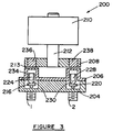
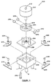
- a coaxial S-switch 200 embodying the invention has an RF cavity housing 204 including a cover 206, an actuator 208 and a motor 210.
- the motor 210 is connected to the actuator 208 by a shaft 212.
- Figure 4 shows a perspective view of the switch 200.
- the switch 200 has four conductor paths located in the RF cavity housing 204.
- Four movable connectors or reeds 214, 216, 218, 220 are connected to reed magnets 222, 224, 226, 228 respectively.
- Each of the connectors 214, 216, 218, 220 contains a support 230 for the reed magnet of that particular connector.
- Each reed magnet is located approximately at a longitudinal centre of each connector.
- the housing 204 contains four ports 1, 2, 3, 4 (only two of which are shown in Figure 3, and only three of which are shown in Figure 4).
- the ports are arranged in a square configuration.
- the cover 206 can be affixed to the housing 204 in a sealed relationship by a threaded bolt 232.
- the cover 206 contains four cylindrically-shaped projections 234, the projections being arranged relative to one another so that when the cover is in place on the housing 204, as shown in Figure 3, one support 230 is located at least partially in each projection 234.
- the actuator 208 has a circular shape and contains four magnets 236, 238, 240, 242, one of which is mounted in each of openings 244 in said actuator.
- the reed magnets are arranged in a generally square configuration and the magnets of the actuator have the same generally square configuration as said reed magnets. Adjacent magnets of said actuator have different polarities facing the housing.
- the magnets 236, 240 have a North polarity facing the actuator 206 and the magnets 238, 242 have a South polarity facing the actuator 206. Since the reed magnets 222, 224, 226, 228 all have the same polarity, in any one position of the actuator, two of the connectors are repelled and two of the connectors are attracted.
- the actuator has two distinct positions. In a first position, a first and third reed magnet is attracted and a second and fourth reed magnet is repelled. In a second position, a second and fourth reed magnet is attracted and a first and third reed magnet is repelled.
- the switch is designed so that a conductor path is connected when a reed magnet for that path is repelled by a corresponding magnet of the actuator.
- a magnet of the actuator is said to align with a magnet of the housing when the two magnets are aligned with one another.
- the wall 213 forms a wall of said housing and separates each of the reed magnets 224 from the actuator 208, said housing being completely sealed from said actuator.
- the stepper motor 210 repositions the actuator by rotating it through 90° at one time. The motor can rotate in the same direction through each step or back and forth, as desired.
- a coaxial S-switch 246 is virtually identical to the switch 200 except that the magnetically transparent wall 213 has been removed.
- the same reference numerals are used in Figure 5 to identify those components that are similar or identical to those of Figure 3.
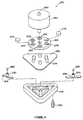
- a T-switch 250 having a motor 252, an actuator 254, a cover 256 and a housing 258.
- the motor 252 has a shaft 260.
- the housing 258, which includes the cover 256 has six conductor paths, three along the periphery of the housing and three radially extending from a centre of the housing.
- the switch 250 has four ports 262, only one of which is shown.
- There are three short connectors 264 having supports 230 and reed magnets 266, only one of which is shown.
- the short connectors 264 are designed to be placed in the radial connecting paths.
- the long connectors 268 are designed to be located in the conductor paths along a periphery of the housing 258.
- the cover 256 has one cylindrically-shaped projection 234 thereon for receiving each of the reed magnets 266 and the supports 230.
- the actuator 254 contains a total of six magnets, 270, 272, 274, 276, 278, 280 which are each mounted in an opening 244.
- the polarity of all of the reed magnets will be identical. If the reed magnets 266 of the switch 250 have a North polarity, the magnets 270, 276 can also have a North polarity facing the housing 258. The remaining magnets 272, 274, 278, 280 of the actuator can then have a South polarity.
- the T-switch 250 has three distinct positions.
- the magnets 270, 276 will repel the reed magnet of a first long connector 268 and the reed magnet of a first short connector 264 normal thereto, thereby completing the connection in the conductor paths in which said connectors are located.
- Ports 1, 2 are connected and ports 3, 4 are connected in this position.
- the remaining reed magnets and connectors will be attracted to the remaining four magnets and the conductor paths in which these connectors are located will be interrupted.
- a second long connector and a second short connector normal thereto will be repelled and the remaining connectors will be attracted.
- Ports 2, 3 are connected and ports 1, 4 are connected in this position.
- a third long connector 268 and a third short connector 264 normal thereto will be repelled and the remaining connectors will be attracted. Ports 3, 1 are connected and ports 2, 4 are connected in this position. In all three positions, the same magnets 270, 276 will cause the corresponding reed magnets to be repelled and, therefore, the conductor path to be connected.
- the three reed magnets for the long connectors are located in a circular format.
- the reed magnets for the short connectors are located in a somewhat smaller circular format.
- magnets of the actuator for the switches 200, 250 have been described as having particular polarities, several different polarities and also different patterns or arrangements of the magnets are possible depending on the manner in which one desires a particular switch to operate.
- the connectors have been described as connecting the conductor path in which they are located when the reed magnet is repelled by the corresponding magnet of the actuator. In some situations, it can be beneficial to have the conducting path connect by attraction of the magnets rather than repulsion.
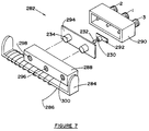
- FIG 7 there is shown an exploded perspective view of a C-switch 282 that is operated by a solenoid 284 having coils 286.
- An actuator 288 is slidable back and forth and has two distinct positions.
- An RF cavity housing 290 has three ports 1, 2, 3 and two conductor paths.
- a connector 292 has a support 230, a reed magnet 232 and is located in the conductor path between port 1 and port 3.
- An identical connector, support and reed magnet having the same polarity is located (but not shown in the drawing) in the conductor path between port 1 and port 2.
- the housing 290 includes a cover 294 having cylindrically-shaped projections 234 to receive the reed magnet and support of each of the connectors.
- the actuator 288 On the basis that the two reed magnets 232 (only one of which is shown in Figure 7) have a North polarity facing the actuator, the actuator 288 has three magnets 296, 298, 300. The magnet 296 of the actuator has a North polarity facing the housing 290. The remaining two magnets 298, 300 have a South polarity facing the housing 290.
- the switch 282 is designed so that the conductor paths are connected when the reed magnets 232 are repelled and interrupted when the reed magnets 232 are attracted to the magnets of the actuator.
- the magnet 296 In a first position shown in Figure 7, the magnet 296 will repel a corresponding magnet 232 and therefore the connector 292 will connect the conductor path between port 1 and port 3. Simultaneously, the magnet 298 will attract the corresponding magnet 232 and therefore the connector 292 (not shown in Figure 7) will interrupt the conductor path between port 1 and port 2.
- the solenoid When the solenoid is activated to shift the actuator linearly to the left from the position shown in Figure 7, in a second position of the actuator, the magnet 296 will then correspond to the reed magnet 232 that is not shown in Figure 7, thereby repelling that magnet and the connector 292 (also not shown in Figure 7) and the conductor path between port 1 and port 2 will be connected. Simultaneously, the magnet 300 will correspond to the reed magnet 232 for the connector 292 between port 1 and port 3, thereby interrupting that conductor path. When the solenoid is reactivated, the actuator will shift back to the first position.
- Figures 8 and 9 show further embodiments of C-switches. Those components of Figures 8 and 9 that are identical to the components of Figure 7 are identified with the same reference numeral. The C-switches shown in Figures 8 and 9 differ with respect to the actuators.
- a C-switch 302 has a circular rotatable actuator 304 which is moved from a first position to a second position by a stepper motor 306 having a shaft 308. Each time the stepper motor moves the actuator, the actuator rotates through 180°. Just like Figure 7, there is a second connector 292, support 230 and magnet 232 located in the conductor path between Ports one and two which is not shown in Figure 8. Magnets 310, 312 of the actuator 304 have the opposite polarity facing the housing 290.
- the switch 302 will operate in identical fashion through a first and second position as already described for the switch 282.
- a C-switch 313 has an actuator 314 with a cylindrical shape.
- the actuator 314 is activated by a stepper motor 316 having a shaft 318 that is connected to the actuator 314.
- Magnets 320, 322 are mounted in suitable openings 324 in the actuator 314.
- the magnets 320, 322 have opposite polarities towards an exterior of the actuator 314.
- the openings 324 can extend entirely through the actuator 314 and the magnets 320, 322 can be long enough so that a North polarity is located at one side of the actuator and a South polarity at the opposite side of the actuator for one magnet while the other magnet is mounted in a reversed position.
- the magnets 320, 322 could be shorter so that they extend only partially through the actuator 314 and a second set of magnets of opposite polarity could be mounted in the opposite side (not shown in Figure 9) of said actuator.
- at least one of the magnets could be closer to the surface of the actuator on one side than it is on the other side in order to vary the force on the corresponding reed magnet from one actuator position to the other.
- the switch 313 has a second connector 292, support 230 and reed magnet 232 located in the conductor path between Ports one and two that is not shown in Figure 9.
- Each activation of the stepper motor 316 rotates the cylindrical actuator 314 by 180°. If the two reed magnets 232 of the housing 290 have a North polarity facing the actuator 314 and the magnet 320 has a North polarity facing the housing 290 in the position shown in Figure 9, then the magnet 324 will have a South polarity facing the housing 290.
- the switch 313 will then operate identically to the switch 282 when the stepper motor 316 is activated to rotate the actuator 314 through 180°.
- the switch can be made small enough to have a cross-sectional area normal to an axis of movement of the reed magnets of substantially 0.95 square inches (24,13 mm.).
- a switch can have a smaller motor as some of the detent force required to maintain the actuator in position can be provided by the magnetic force between the magnets of the actuator and the housing.
- the connectors can be made of various materials that will be suitable, including, without limitation, a conducting plastic material.
Landscapes
- Switches That Are Operated By Magnetic Or Electric Fields (AREA)
- Details Of Connecting Devices For Male And Female Coupling (AREA)
Claims (16)
- Mikrowellenschalter mit einem HF-Hohlraumgehäuse (204), einem Stellglied (208) und einem Kraftmittel (210) zum Neupositionieren des Stellglieds, welche wie folgt angeordnet sind:(a) wobei das Gehäuse mindestens zwei Leiterstrecken aufweist, welche mindestens drei Öffnungen (1, 2, 3) miteinander verbinden, wobei in jeder Leiterstrecke ein Verbinder angeordnet ist und sich zwischen zwei Öffnungen erstreckt, wobei jeder Verbinder eine erste Position und eine zweite Position aufweist, welche voneinander linear versetzt liegen, wobei in einer Position jeder Verbinder eine Leiterstrecke verbindet, in welcher der Verbinder angeordnet ist, während in einer anderen Position jeder Verbinder die Leiterstrecke unterbricht;wobei der Schalter dadurch gekennzeichnet ist, daß(b) das Stellglied mindestens zwei Permanentmagnete (236, 238) aufweist, wobei zumindest einer der Permanentmagnete von entgegengesetzter Polarität in bezug auf zumindest einen anderen der Permanentmagnete ist;(c) das Gehäuse zumindest zwei Permanentmagnete (222, 224) derselben Polarität enthält, welche je einen eigenen, darauf angeordneten Verbinder (214, 216) aufweisen, wobei die Verbindermagnete (222, 224) des Gehäuses und die Permanentmagnete des Stellglieds angeordnet sind, um miteinander in Wechselwirkung zu treten, wenn sich das Stellglied in einer geeigneten Position befindet, so daß ein Magnet des Stellglieds mit einem entsprechenden Verbindermagneten des Gehäuses ausgerichtet ist;(d) die Magnete des Stellglieds in bezug auf Polarität derart angeordnet sind, daß, wenn das Stellglied durch das Kraftmittel in eine Position bewegt wird, zumindest ein Magnet (236) des Stellglieds einen entsprechenden Verbindermagneten (222) des Gehäuses anzieht und somit den Verbinder (214) veranlaßt, eine Leiterstrecke entweder zu schließen oder zu unterbrechen, während zur gleichen Zeit ein anderer Magnet (238) des Stellglieds einen entsprechenden Verbindermagneten (222) des Gehäuses abstößt und somit den Verbinder (216) veranlaßt, eine andere Leiterstrecke dementsprechend entweder zu schließen oder zu unterbrechen;wobei die Bewegung aller Magnete koordiniert wird, so daß geeignete Leiterstrecken gleichzeitig verbunden und unterbrochen werden, wobei das Stellglied, das Kraftmittel, die Verbindermagnete und die Verbinder die einzigen beweglichen Teile des Schalters sind, wobei keine mechanische Verbindung zwischen den Magneten des Stellglieds und den Verbindermagneten des Gehäuses besteht.
- Mikrowellenschalter nach Anspruch 1, wobei das Gehäuse eine Reihe von Öffnungen (248) zwischen jedem der Verbindermagnete und dem Stellglied aufweist.
- Mikrowellenschalter nach Anspruch 1, wobei das Gehäuse eine magnetisch transparente Wand (213) aufweist, welche eine Wand des Gehäuses bildet und jeden der Verbindermagnete vom Stellglied trennt, wobei das Gehäuse vom Stellglied vollständig abgeschlossen ist.
- Mikrowellenschalter nach Anspruch 1, wobei das Stellglied eine kreisförmige Gestalt aufweist und das Kraftmittel ein Motor ist, wobei der Motor das Stellglied durch Drehen des Stellglieds neupositioniert.
- Mikrowellenschalter nach einem der Ansprüche 2, 3 oder 4, wobei der Schalter ein S-Schalter (246) ist und das Gehäuse vier Leiterstrecken, vier Öffnungen (1, 2, 3, 4), vier Verbindermagnete (222, 224, 226, 228) und vier Verbinder (214, 216, 218, 220) umfaßt, wobei die Verbinder und die Verbindermagnete in einer im allgemeinen quadratischen Konfiguration angeordnet sind, wobei jeder Verbindermagnet mit einem eigenen Verbinder verbunden ist, wobei das Stellglied vier Magnete (236, 238, 240, 242) umfaßt, welche in derselben im allgemeinen quadratischen Konfiguration wie die Verbindermagnete angeordnet sind, wobei die Magnete des Stellglieds dem Gehäuse gegenüber verschiedene Polaritäten aufweisen, so daß zwei der Magneten (236, 240) eine nördliche Polarität und zwei der Magneten (238, 242) eine südliche Polarität aufweisen, wobei das Stellglied zwei unterschiedliche Positionen aufweist, wobei bei jeder der beiden Positionen zwei der Verbindermagnete von den Permanentmagneten des Stellglieds angezogen und gleichzeitig zwei der Verbindermagnete abgestoßen werden.
- Mikrowellenschalter nach einem der Ansprüche 2, 3 oder 4, wobei der Schalter ein S-Schalter ist und das Gehäuse vier Leiterstrecken, vier Öffnungen, vier Verbindermagnete und vier Verbinder umfaßt, wobei die Verbinder und die Verbindermagnete in einer im allgemeinen quadratischen Konfiguration angeordnet sind, wobei das Stellglied vier Magnete umfaßt, welche in derselben im allgemeinen quadratischen Konfiguration wie die Verbindermagnete angeordnet sind, wobei benachbarte Magnete des Stellglieds dem Gehäuse gegenüber verschiedene Polaritäten aufweisen, so daß jeder zweite Magnet (236, 240) des Stellglieds eine nördliche Polarität aufweist und ein Magnet mit einer südlichen Polarität zwischen den Magneten mit nördlicher Polarität angeordnet ist, wobei das Stellglied zwei unterschiedliche Positionen aufweist, wobei bei jeder der beiden Positionen zwei der Verbindermagnete von den Permanentmagneten des Stellglieds angezogen und gleichzeitig zwei der Verbindermagnete abgestoßen werden, wobei in einer ersten Position ein erster und ein dritter Verbindermagnet (222, 226) abgestoßen werden und in einer zweiten Position ein zweiter und ein vierter Verbindermagnet (224, 228) abgestoßen werden.
- Mikrowellenschalter nach einem der Ansprüche 2, 3, 4, wobei der Schalter ein C-Schalter (282) ist und das Gehäuse (290) zwei Leiterstrecken, drei Öffnungen (1, 2, 3), zwei Verbindermagnete (232) und zwei Verbinder (292) umfaßt, wobei jeder Verbindermagnet mit einem eigenen Verbinder verbunden ist, wobei ein Verbinder die Öffnungen Eins und Zwei und der andere Verbinder die Öffnungen Zwei und Drei verbindet, wobei auch das Stellglied (288) drei Permanentmagnete (296, 298, 300) umfaßt, welche derart angeordnet sind, daß in jeder Position jeweils zwei Permanentmagnete den Verbindermagneten entsprechen, wobei die Magnete des Stellglieds entgegengesetzte Polaritäten aufweisen, so daß zumindest ein Magnet (298, 300) eine südliche Polarität aufweist und der andere Magnet (296) eine nördliche Polarität aufweist, wobei das Stellglied zwei unterschiedliche Positionen aufweist, wobei in einer ersten Position ein erster Verbindermagnet angezogen und zugleich ein zweiter Verbindermagnet abgestoßen wird und in einer zweiten Position ein zweiter Verbindermagnet angezogen wird und ein erster Verbindermagnet abgestoßen wird.
- Mikrowellenschalter nach einem der Ansprüche 2, 3, 4, wobei der Schalter ein T-Schalter (250) ist und das Gehäuse (258) sechs Leiterstrecken, vier Öffnungen (1, 2, 3, 4), sechs verbindermagnete (266) und sechs Verbinder (264, 268) umfaßt, wobei jeder Verbindermagnet (266) mit einem eigenen Verbinder verbunden ist, wobei ein Verbinder die Öffnungen Eins und Zwei, ein Verbinder die Öffnungen Zwei und Drei, ein Verbinder die Öffnungen Eins und Drei, ein Verbinder die Öffnungen Eins und Vier, ein Verbinder die Öffnungen Zwei und Vier sowie ein Verbinder die Öffnungen Drei und Vier verbindet, wobei das Stellglied (254) ebenfalls sechs Permanentmagnete (270, 272, 274, 276, 278, 280) umfaßt, welche derart angeordnet sind, daß sie den Verbindermagneten entsprechen, wobei zumindest einer der Magnete des Stellglieds eine zu anderen Magneten des Stellglieds entgegengesetzte Polarität aufweist, wobei das Stellglied zumindest drei unterschiedliche Positionen aufweist, wobei in jeder der Positionen ein oder mehrere Verbindermagnete angezogen und ein oder mehrere Verbindermagnete abgestoßen werden.
- Mikrowellenschalter nach einem der Ansprüche 2, 3 oder 4, wobei der Schalter ein T-Schalter ist und das Gehäuse sechs Leiterstrecken, vier Öffnungen, sechs Verbindermagnete und sechs Verbinder umfaßt, wobei jeder Verbindermagnet mit einem eigenen Verbinder verbunden ist, wobei ein Verbinder die Öffnungen Eins und Zwei, ein Verbinder die Öffnungen Zwei und Drei, ein Verbinder die Öffnungen Eins und Drei, ein Verbinder die Öffnungen Eins und Vier, ein Verbinder die Öffnungen Zwei und Vier sowie ein Verbinder die Öffnungen Drei und Vier verbindet, wobei das Stellglied ebenfalls sechs Permanentmagnete umfaßt, welche derart angeordnet sind, daß sie den Verbindermagneten entsprechen, wobei die Magnete des Stellglieds unterschiedliche Polaritäten aufweisen, wobei ein erster und ein zweiter Magnet (270, 272) und ein vierter und ein fünfter Magnet (276, 278) des Stellglieds dem Gehäuse gegenüber eine Polarität aufweisen und ein dritter und ein sechster Magnet (274, 280) des Stellglieds dem Gehäuse gegenüber eine andere Polarität aufweisen, wobei das Stellglied drei unterschiedliche Positionen aufweist, wobei in einer ersten Position der erste und der vierte Verbindermagnet abgestoßen und die übrigen Verbindermagnete angezogen werden, in einer zweiten Position der zweite und der fünfte Verbindermagnet abgestoßen und die übrigen Magnete angezogen werden, in einer dritten Position der dritte und der sechste Verbindermagnet abgestoßen und die übrigen Verbindermagnete angezogen werden.
- Mikrowellenschalter nach einem der Ansprüche 1, 2 oder 3, wobei der Schalter ein C-Schalter ist und das Gehäuse zwei Leiterstrecken, drei Öffnungen, zwei Verbindermagnete und zwei Verbinder umfaßt, wobei jeder Verbindermagnet mit einem eigenen Verbinder verbunden ist, wobei ein Verbinder die Öffnungen Eins und Zwei und ein Verbinder die Öffnungen Eins und Drei verbindet, wobei das Stellglied drei Permanentmagnete umfaßt, wobei die Magnete des Stellglieds in einer geraden Linie angeordnet und von einander beabstandet sind, derart, daß, wenn sich das Stellglied in Längsrichtung von einer ersten Position zu einer zweiten Position bewegt, zwei der drei Magnete des Stellglieds den Verbindermagneten des Gehäuses entsprechen, wobei ein mittlerer Magnet des Stellglieds dieselbe Polarität wie die Verbindermagnete aufweist, um die Verbindermagnete abzustoßen, und die übrigen Magnete des Stellglieds eine den Verbindermagneten entgegengesetzte Polarität aufweisen, um die Verbindermagnete anzuziehen, wobei das Stellglied zwei unterschiedliche Positionen aufweist, wobei in einer ersten Position der erste Verbindermagnet abgestoßen und der zweite Verbindermagnet angezogen wird, in einer zweiten Position der erste Verbindermagnet angezogen und der zweite Verbindermagnet abgestoßen wird.
- Mikrowellenschalter nach einem der Ansprüche 1, 2 oder 3, wobei der Schalter ein C-Schalter (302) ist und das Gehäuse (290) zwei Leiterstrecken, drei Öffnungen (1, 2, 3), zwei Verbindermagnete (232) und zwei Verbinder (292) umfaßt, wobei jeder Verbindermagnet (232) mit einem eigenen Verbinder verbunden ist, wobei ein Verbinder die Öffnungen Eins und Zwei und ein Verbinder die Öffnungen Eins und Drei verbindet, wobei das Stellglied (304) drehbar ist und zwei Permanentmagnete (310, 312) umfaßt, wobei die Magnete derart dimensioniert und angeordnet sind, um den Verbindermagneten zu entsprechen, wobei das Stellglied (304) zwei Positionen aufweist, wobei in einer ersten Position der erste Verbindermagnet abgestoßen und der zweite Verbindermagnet angezogen wird, in einer zweiten Position, wobei die zweite Position die Drehung des Stellglieds um 180° darstellt, der erste Verbindermagnet angezogen und der zweite Verbindermagnet abgestoßen wird.
- Mikrowellenschalter nach einem der Ansprüche 1, 2 oder 3, wobei der Schalter ein C-Schalter (313) ist und das Gehäuse (290) zwei Leiterstrecken, drei Öffnungen (1, 2, 3), zwei Verbindermagnete (232) und zwei Verbinder (292) umfaßt, wobei jeder Verbindermagnet (232) mit einem eigenen Verbinder verbunden ist, wobei ein Verbinder die Öffnungen Eins und Zwei und ein Verbinder die Öffnungen Eins und Drei verbindet, wobei das Stellglied (314) eine zylindrische Gestalt besitzt und an entgegengesetzten Seiten einer seiner Außenflächen Magnete (320, 322) aufweist, wobei zwei Magnete (320, 322) auf einer Seite des zylindrischen Stellglieds und zwei Magnete (320, 322) auf der anderen Seite des zylindrischen Stellglieds (314) angeordnet sind, wobei die Magnete (320, 322) auf derselben Seite des Stellglieds unterschiedliche Polarität besitzen, sowie Mittel (316) zum Drehen des zylindrischen Stellglieds um seine Längsachse aufweist, wobei die Magnete (320, 322) des Stellglieds (314) dimensioniert und angeordnet sind, um den Verbindermagneten (232) zu entsprechen, wobei das Stellglied zwei unterschiedliche Positionen aufweist, wobei in einer ersten Position der erste Verbindermagnet abgestoßen und der zweite Verbindermagnet angezogen wird und in einer zweiten Position, wobei die zweite Position durch Drehen des Stellglieds um seine Längsachse um 180° erreicht wird, der erste Verbindermagnet angezogen und der zweite Verbindermagnet abgestoßen wird.
- Mikrowellenschalter nach einem der Ansprüche 2, 3 oder 4, wobei der Schalter aus der Gruppe von C-Schaltern oder T-Schaltern ausgewählt ist und eine zu einer Bewegungsachse der Verbindermagnete normal stehende Querschnittsfläche von im wesentlichen 0,95 Quadratzoll (6,13 cm) aufweist.
- Mikrowellenschalter nach einem der Ansprüche 2, 3 oder 4, wobei eine Leiterstrecke verbunden ist, wenn der Verbindermagnet für den Verbinder für diese Strecke abgestoßen ist, und unterbrochen ist, wenn der Verbindermagnet (224) für diese Strecke angezogen ist.
- Mikrowellenschalter nach einem der Ansprüche 2, 3, 4, wobei eine magnetische Kraft zwischen Magneten des Stellglieds und des Gehäuses, welche zueinander angezogen werden, zumindest für eine gewisse Arretierungskraft sorgt, welche erforderlich ist, um den Schalter in einer bestimmten Position zu halten.
- Mikrowellenschalter nach einem der Ansprüche 2, 3 oder 4, wobei jeder der Verbindermagnete und Träger ungefähr in einer longitudinalen Mitte jedes Verbinders (216) angeordnet ist.
Applications Claiming Priority (2)
| Application Number | Priority Date | Filing Date | Title |
|---|---|---|---|
| CA002014585A CA2014585C (en) | 1990-04-12 | 1990-04-12 | C-, s- and t-switches operated by permanent magnets |
| CA2014585 | 1990-04-12 |
Publications (3)
| Publication Number | Publication Date |
|---|---|
| EP0451974A2 EP0451974A2 (de) | 1991-10-16 |
| EP0451974A3 EP0451974A3 (en) | 1992-02-05 |
| EP0451974B1 true EP0451974B1 (de) | 1996-03-06 |
Family
ID=4144750
Family Applications (1)
| Application Number | Title | Priority Date | Filing Date |
|---|---|---|---|
| EP91302471A Expired - Lifetime EP0451974B1 (de) | 1990-04-12 | 1991-03-21 | C-, S- und T-Schalter, betätigt von Permanentmagneten |
Country Status (4)
| Country | Link |
|---|---|
| US (1) | US5065125A (de) |
| EP (1) | EP0451974B1 (de) |
| CA (1) | CA2014585C (de) |
| DE (1) | DE69117558T2 (de) |
Families Citing this family (22)
| Publication number | Priority date | Publication date | Assignee | Title |
|---|---|---|---|---|
| US5281936A (en) * | 1992-06-01 | 1994-01-25 | Teledyne Industries, Inc. | Microwave switch |
| DE59308825D1 (de) * | 1993-03-31 | 1998-09-03 | Bosch Gmbh Robert | Koaxialschalter |
| CA2099147C (en) * | 1993-06-25 | 1995-07-18 | Klaus Gunter Engel | Radio frequency switch and method of operation therefor |
| US5451918A (en) * | 1994-05-04 | 1995-09-19 | Teledyne Industries, Inc. | Microwave multi-port transfer switch |
| US5929731A (en) * | 1996-05-08 | 1999-07-27 | Jackson Research, Inc. | Balanced magnetic proximity switch assembly |
| US5877664A (en) * | 1996-05-08 | 1999-03-02 | Jackson, Jr.; John T. | Magnetic proximity switch system |
| US5712603A (en) * | 1996-08-09 | 1998-01-27 | Kmw Usa, Inc. | Multipole multiposition microwave switch with a common redundancy |
| US5828268A (en) * | 1997-06-05 | 1998-10-27 | Hughes Electronics Corporation | Microwave switches and redundant switching systems |
| US5936482A (en) * | 1997-11-20 | 1999-08-10 | Hughes Electronics Corporation | Three dimensional polyhedral-shaped microwave switches |
| US6133812A (en) * | 1998-05-21 | 2000-10-17 | Relcomm Technologies, Inc. | Switching relay with magnetically resettable actuator mechanism |
| US5952902A (en) * | 1999-03-12 | 1999-09-14 | Kich; Rolf | Coaxial "M" switch |
| US6037849A (en) * | 1999-07-26 | 2000-03-14 | Delaware Capital Formation, Inc. | Microwave switch having magnetically retained actuator plate |
| US6618022B2 (en) | 2001-07-20 | 2003-09-09 | Delta Systems, Inc. | Radio frequency powered switch |
| US6856212B2 (en) * | 2002-12-16 | 2005-02-15 | Com Dev Ltd. | Incomplete mechanical contacts for microwave switches |
| US7135947B2 (en) | 2004-01-29 | 2006-11-14 | Com Dev Ltd. | Hybrid microwave T-switch actuator |
| US20080283379A1 (en) * | 2007-05-18 | 2008-11-20 | Teledyne Technologies Incorporated | Coaxial switch with reduced tribo-electric charge accumulation |
| US7876185B2 (en) * | 2008-05-05 | 2011-01-25 | Teledyne Technologies Incorporated | Electromagnetic switch |
| CN102544645A (zh) * | 2011-12-29 | 2012-07-04 | 航天时代电子技术股份有限公司 | 一种模块化t型微波开关 |
| CN103050746B (zh) * | 2012-11-20 | 2015-01-14 | 航天时代电子技术股份有限公司 | 一种电机型驱动的t型微波开关 |
| US10122251B2 (en) | 2015-05-29 | 2018-11-06 | Com Dev Ltd. | Sequential actuator with sculpted active torque |
| CN105097367B (zh) * | 2015-07-03 | 2018-07-24 | 中国电子科技集团公司第四十一研究所 | 一种t型同轴机电开关 |
| CN105633514B (zh) * | 2015-12-25 | 2019-03-15 | 中国航天时代电子公司 | 一种星载微波开关低能耗转动驱动装置 |
Family Cites Families (9)
| Publication number | Priority date | Publication date | Assignee | Title |
|---|---|---|---|---|
| DE1938777A1 (de) * | 1969-07-30 | 1971-02-11 | Spinner Dr Ing Georg | Koaxialdrehschalter,insbesondere fuer HF-Schaltfelder |
| FR2370350A1 (fr) * | 1976-11-05 | 1978-06-02 | Serras Paulet Edouard | Commutateur rotatif, a aimants mobiles |
| US4298847A (en) * | 1980-04-21 | 1981-11-03 | Dynatech - Uz, Inc. | Multiposition microwave switch with independent termination |
| DE3483959D1 (de) * | 1983-12-22 | 1991-02-21 | Teldix Gmbh | Hohlleiterschalter. |
| US4520331A (en) * | 1983-12-27 | 1985-05-28 | Transco Products, Inc. | Rotary actuator for a microwave switch |
| DE3702417A1 (de) * | 1987-01-28 | 1988-08-11 | Teldix Gmbh | Anordnung zum einstellen eines rotors |
| US4908588A (en) * | 1988-06-02 | 1990-03-13 | Hu Development Corporation | Matrix switch |
| CA1283680C (en) * | 1988-09-28 | 1991-04-30 | Klaus Gunter Engel | Microwave c-switches and s-switches |
| US4965542A (en) * | 1989-02-28 | 1990-10-23 | Victor Nelson | Magnetic switch for coaxial transmission lines |
-
1990
- 1990-04-12 CA CA002014585A patent/CA2014585C/en not_active Expired - Lifetime
- 1990-05-02 US US07/517,590 patent/US5065125A/en not_active Expired - Lifetime
-
1991
- 1991-03-21 EP EP91302471A patent/EP0451974B1/de not_active Expired - Lifetime
- 1991-03-21 DE DE69117558T patent/DE69117558T2/de not_active Expired - Fee Related
Also Published As
| Publication number | Publication date |
|---|---|
| DE69117558T2 (de) | 1996-09-19 |
| EP0451974A3 (en) | 1992-02-05 |
| EP0451974A2 (de) | 1991-10-16 |
| CA2014585A1 (en) | 1991-10-12 |
| CA2014585C (en) | 1992-11-03 |
| DE69117558D1 (de) | 1996-04-11 |
| US5065125A (en) | 1991-11-12 |
Similar Documents
| Publication | Publication Date | Title |
|---|---|---|
| EP0451974B1 (de) | C-, S- und T-Schalter, betätigt von Permanentmagneten | |
| EP0592083B1 (de) | Bürstenloser Drehmomentantrieb mit Davermagneten | |
| CA2014584C (en) | C-, t- and s-switches that are mechanically operated by a rotary actuator | |
| US4447793A (en) | Rotary actuators | |
| US5829987A (en) | Electromechanical connection device | |
| US6922123B2 (en) | Magnetic detent action for switches | |
| GB2199926A (en) | Centring device for personally actuated commander | |
| US5499006A (en) | Radio frequency switch and method of operation therefor | |
| US4965542A (en) | Magnetic switch for coaxial transmission lines | |
| US5714728A (en) | Electric switch | |
| US4520331A (en) | Rotary actuator for a microwave switch | |
| US4851801A (en) | Microwave C-switches and S-switches | |
| US4665373A (en) | Small size waveguide switching device | |
| US3660789A (en) | Rotary reed switch | |
| US3458839A (en) | Locking reed and ball switches and matrices | |
| US5936482A (en) | Three dimensional polyhedral-shaped microwave switches | |
| US4330766A (en) | Electromechanical switch | |
| US5742012A (en) | Switching field | |
| US3537047A (en) | Electric snap switch | |
| CA2300104C (en) | Coaxial "m" switch | |
| CN217035555U (zh) | 一种三态继电器 | |
| US5686875A (en) | Mercury wetted switch | |
| CN223297032U (zh) | 一种微型单刀多掷带负载射频开关 | |
| CN110797611A (zh) | 一种紧凑型微波开关位置状态指示机构 | |
| US3153711A (en) | Rotary armature electromagnetic relay |
Legal Events
| Date | Code | Title | Description |
|---|---|---|---|
| PUAI | Public reference made under article 153(3) epc to a published international application that has entered the european phase |
Free format text: ORIGINAL CODE: 0009012 |
|
| AK | Designated contracting states |
Kind code of ref document: A2 Designated state(s): DE FR GB IT SE |
|
| PUAL | Search report despatched |
Free format text: ORIGINAL CODE: 0009013 |
|
| AK | Designated contracting states |
Kind code of ref document: A3 Designated state(s): DE FR GB IT SE |
|
| RHK1 | Main classification (correction) |
Ipc: H01P 1/10 |
|
| 17P | Request for examination filed |
Effective date: 19920804 |
|
| 17Q | First examination report despatched |
Effective date: 19940614 |
|
| GRAA | (expected) grant |
Free format text: ORIGINAL CODE: 0009210 |
|
| AK | Designated contracting states |
Kind code of ref document: B1 Designated state(s): DE FR GB IT SE |
|
| ITF | It: translation for a ep patent filed | ||
| REF | Corresponds to: |
Ref document number: 69117558 Country of ref document: DE Date of ref document: 19960411 |
|
| PG25 | Lapsed in a contracting state [announced via postgrant information from national office to epo] |
Ref country code: SE Effective date: 19960606 |
|
| ET | Fr: translation filed | ||
| PLBE | No opposition filed within time limit |
Free format text: ORIGINAL CODE: 0009261 |
|
| STAA | Information on the status of an ep patent application or granted ep patent |
Free format text: STATUS: NO OPPOSITION FILED WITHIN TIME LIMIT |
|
| 26N | No opposition filed | ||
| REG | Reference to a national code |
Ref country code: GB Ref legal event code: IF02 |
|
| PGFP | Annual fee paid to national office [announced via postgrant information from national office to epo] |
Ref country code: GB Payment date: 20090320 Year of fee payment: 19 |
|
| PGFP | Annual fee paid to national office [announced via postgrant information from national office to epo] |
Ref country code: IT Payment date: 20090325 Year of fee payment: 19 Ref country code: DE Payment date: 20090525 Year of fee payment: 19 |
|
| PGFP | Annual fee paid to national office [announced via postgrant information from national office to epo] |
Ref country code: FR Payment date: 20090318 Year of fee payment: 19 |
|
| GBPC | Gb: european patent ceased through non-payment of renewal fee |
Effective date: 20100321 |
|
| REG | Reference to a national code |
Ref country code: FR Ref legal event code: ST Effective date: 20101130 |
|
| PG25 | Lapsed in a contracting state [announced via postgrant information from national office to epo] |
Ref country code: FR Free format text: LAPSE BECAUSE OF NON-PAYMENT OF DUE FEES Effective date: 20100331 |
|
| PG25 | Lapsed in a contracting state [announced via postgrant information from national office to epo] |
Ref country code: DE Free format text: LAPSE BECAUSE OF NON-PAYMENT OF DUE FEES Effective date: 20101001 |
|
| PG25 | Lapsed in a contracting state [announced via postgrant information from national office to epo] |
Ref country code: GB Free format text: LAPSE BECAUSE OF NON-PAYMENT OF DUE FEES Effective date: 20100321 Ref country code: IT Free format text: LAPSE BECAUSE OF NON-PAYMENT OF DUE FEES Effective date: 20100321 |