EP0452019A2 - Methods and apparatus for optimizing prefetch caching - Google Patents
Methods and apparatus for optimizing prefetch caching Download PDFInfo
- Publication number
- EP0452019A2 EP0452019A2 EP91302878A EP91302878A EP0452019A2 EP 0452019 A2 EP0452019 A2 EP 0452019A2 EP 91302878 A EP91302878 A EP 91302878A EP 91302878 A EP91302878 A EP 91302878A EP 0452019 A2 EP0452019 A2 EP 0452019A2
- Authority
- EP
- European Patent Office
- Prior art keywords
- cylinders
- bands
- tracks
- disc drives
- block numbers
- Prior art date
- Legal status (The legal status is an assumption and is not a legal conclusion. Google has not performed a legal analysis and makes no representation as to the accuracy of the status listed.)
- Granted
Links
Images

Classifications
-
- G—PHYSICS
- G06—COMPUTING OR CALCULATING; COUNTING
- G06F—ELECTRIC DIGITAL DATA PROCESSING
- G06F3/00—Input arrangements for transferring data to be processed into a form capable of being handled by the computer; Output arrangements for transferring data from processing unit to output unit, e.g. interface arrangements
- G06F3/06—Digital input from, or digital output to, record carriers, e.g. RAID, emulated record carriers or networked record carriers
- G06F3/0601—Interfaces specially adapted for storage systems
-
- G—PHYSICS
- G06—COMPUTING OR CALCULATING; COUNTING
- G06F—ELECTRIC DIGITAL DATA PROCESSING
- G06F12/00—Accessing, addressing or allocating within memory systems or architectures
- G06F12/02—Addressing or allocation; Relocation
- G06F12/08—Addressing or allocation; Relocation in hierarchically structured memory systems, e.g. virtual memory systems
- G06F12/0802—Addressing of a memory level in which the access to the desired data or data block requires associative addressing means, e.g. caches
- G06F12/0866—Addressing of a memory level in which the access to the desired data or data block requires associative addressing means, e.g. caches for peripheral storage systems, e.g. disk cache
-
- G—PHYSICS
- G06—COMPUTING OR CALCULATING; COUNTING
- G06F—ELECTRIC DIGITAL DATA PROCESSING
- G06F3/00—Input arrangements for transferring data to be processed into a form capable of being handled by the computer; Output arrangements for transferring data from processing unit to output unit, e.g. interface arrangements
- G06F3/06—Digital input from, or digital output to, record carriers, e.g. RAID, emulated record carriers or networked record carriers
- G06F3/0601—Interfaces specially adapted for storage systems
- G06F3/0602—Interfaces specially adapted for storage systems specifically adapted to achieve a particular effect
- G06F3/061—Improving I/O performance
- G06F3/0611—Improving I/O performance in relation to response time
-
- G—PHYSICS
- G06—COMPUTING OR CALCULATING; COUNTING
- G06F—ELECTRIC DIGITAL DATA PROCESSING
- G06F3/00—Input arrangements for transferring data to be processed into a form capable of being handled by the computer; Output arrangements for transferring data from processing unit to output unit, e.g. interface arrangements
- G06F3/06—Digital input from, or digital output to, record carriers, e.g. RAID, emulated record carriers or networked record carriers
- G06F3/0601—Interfaces specially adapted for storage systems
- G06F3/0628—Interfaces specially adapted for storage systems making use of a particular technique
- G06F3/0638—Organizing or formatting or addressing of data
- G06F3/064—Management of blocks
-
- G—PHYSICS
- G06—COMPUTING OR CALCULATING; COUNTING
- G06F—ELECTRIC DIGITAL DATA PROCESSING
- G06F3/00—Input arrangements for transferring data to be processed into a form capable of being handled by the computer; Output arrangements for transferring data from processing unit to output unit, e.g. interface arrangements
- G06F3/06—Digital input from, or digital output to, record carriers, e.g. RAID, emulated record carriers or networked record carriers
- G06F3/0601—Interfaces specially adapted for storage systems
- G06F3/0628—Interfaces specially adapted for storage systems making use of a particular technique
- G06F3/0655—Vertical data movement, i.e. input-output transfer; data movement between one or more hosts and one or more storage devices
- G06F3/0656—Data buffering arrangements
-
- G—PHYSICS
- G06—COMPUTING OR CALCULATING; COUNTING
- G06F—ELECTRIC DIGITAL DATA PROCESSING
- G06F3/00—Input arrangements for transferring data to be processed into a form capable of being handled by the computer; Output arrangements for transferring data from processing unit to output unit, e.g. interface arrangements
- G06F3/06—Digital input from, or digital output to, record carriers, e.g. RAID, emulated record carriers or networked record carriers
- G06F3/0601—Interfaces specially adapted for storage systems
- G06F3/0668—Interfaces specially adapted for storage systems adopting a particular infrastructure
- G06F3/0671—In-line storage system
- G06F3/0683—Plurality of storage devices
- G06F3/0689—Disk arrays, e.g. RAID, JBOD
-
- G—PHYSICS
- G06—COMPUTING OR CALCULATING; COUNTING
- G06F—ELECTRIC DIGITAL DATA PROCESSING
- G06F12/00—Accessing, addressing or allocating within memory systems or architectures
- G06F12/02—Addressing or allocation; Relocation
- G06F12/08—Addressing or allocation; Relocation in hierarchically structured memory systems, e.g. virtual memory systems
- G06F12/0802—Addressing of a memory level in which the access to the desired data or data block requires associative addressing means, e.g. caches
- G06F12/0862—Addressing of a memory level in which the access to the desired data or data block requires associative addressing means, e.g. caches with prefetch
Definitions
- the present invention relates to logical block mapping of logical data blocks on disc type data storage systems, and more particularly to methods and apparatus for logical block to physical sector mapping and access to optimize prefetch caching with disc type data storage systems.
- Modem data processing systems generally use magnetic disc storage systems for storing therein an operating system program and data.
- a disc storage system may comprise an array of disc drives, with each disc drive having a plurality of discs and associated magnetic heads for each of the two magnetic surfaces of each disc.
- Caching of logical data blocks retrieved from the disc drive array is often done to improve the average access time of the disc drive array to requests for logical data blocks from the host data processing system.
- Caching is a technique that puts a small, fast memory, called a cache memory, in front of a large, slow memory, such as the disc drive array, in such a way that the resulting combination approximates a large, fast memory.
- Prefetch blocks are the logical data blocks that the host system has not requested, but are read from the discs in the array into the cache memory because a high probability exists that the host will request them in the near future. In this way, the stored prefetch blocks are available from the cache memory in response to a subsequent request from the host without reaccessing the disc drive array.
- Logical block numbers provide a means for the host system to address physical data on the disc drives without having to be concerned with the physical attributes of the disc drives.
- the logical data blocks are stored in the disc drive address with a physical block location that is mapped to correspond to a drive, band, cylinder, sector address in the array.
- a cylinder is made up of all of the tracks that can be accessed in the array without the need for a seek. For instance, if the disc drive array has five discs so that the array can access ten disc surfaces, it will typically have ten heads. The ten tracks that align beneath those heads at one time make up a cylinder.
- a read operation can be viewed as a three step process.
- the first step is to perform a w seek 7 operation to move the heads to the correct cylinder.
- the second step is to waitforthe disk to rotate around so that the requested LBN passes under the head. This time is termed "rotational latency.”
- the final step is to read the requested LBN as it passes under the head. Because of the sequential way that user processes for the host system access many files, and the policies that operating systems in the data processing systems use to allocate files, there is a tendency for the disc drive array to first see a request for a set of logical data blocks and then shortly after see a request for another set of logical data blocks starting with the block whose LBN is one greater than the last LBN of the first requested set of logical blocks.
- the present invention overcomes the above-described limitation of the prior art block ordering scheme by placing the logical blocks on the tracks of the discs in the array in reverse order so that the logical blocks that have a high probability of being read in the near future can be read into cache memory during the otherwise "wasted" rotational latentcy period.
- the present invention also further increases performance by combining reverse ordered blocks with banding, striping, and compensation for sequential accesses across head switches.
- the present invention optimizes prefetch caching efficiency of disc drive type storage systems by reverse ordering the LBN's when they are stored on the disc surfaces and between discs so that LBN's that immediately follow the number of a requested LBN are automatically stored in the disc drive cache memory during the rotational latency period.
- a number of LBN's are read before the requested LBN is found.
- the LBN's that are read before the requested LBN is found are those LBN's that immediately follow the requested LBN in number.
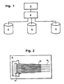
- Figure 1 shows a block diagram of a typical host data processing system 2 that includes a plurality of magnetic disc drives 4.
- the disc drives 4 are coupled to the host system 2 via a disc drive controller 6.
- the host 2 and the controller 6 are shown only in block form in Figure 1 because they are well known components of data processing systems that do not themselves constitute the present invention.
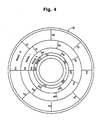
- Each of the disc drives 4 have the basic elements shown in detail in Figure 2. Normally, each of the disc drives 4 respond to a LBN requested by the host 2 via the controller 6 so as to cause an actuator arm 8 in the disc drive 4 to move a set of magnetic heads 10 relative to a corresponding set of magnetic discs 12 to a physical cylinder position corresponding to the cylinder address mapped from the LBN.
- the disc drive 4 in Figure 2 is shown with a set of 10 of the magnetic heads 10 and a corresponding set of 5 of the discs 12, although a greater or lesser number of the heads 10 can be used with a corresponding greater or lesser number of the discs 12, as well known in the art.
- the disc drives 4 may utilize banding to improve their LBN storage density.
- the bands comprise different annular areas of the surfaces of the discs 12 that are each written with a different bit frequency that is proportional to the surface velocities of the respective band to maximize the storage density of the disc drive 4. This is because the discs 12 rotate with a constant angular velocity and can support a constant bit density, so that a track with a large radius can support a higher bit frequency than a track with a small radius.
- Striping is the dispersion of a single 1/0 request across multiple disc drives of a disc drive storage system.
- a "stripe sef consists of two or more disc drives in a disc drive system, with the entire set being presented as a single logical volume for I/O.
- the present invention uses striping primarily to statistically balance the I/O request load among the plurality of discs 12 being striped, rather than leave such load balancing to higher-level system components, or manual management techniques.
- the logical blocks that are presented for I/O are spread across the disc in "chunks". These chunks have a size that may be measured in number of sectors, tracks, cylinders, bands, or even drives. For example, if the chunk size is 10 tracks, then tracks 0 through 9 are on a first one of the disc drives 4, tracks 10 through 19 are on a second, and so forth.
- Such banding and striping of the disc drives 4 presents special problems to reverse ordering the way the LBN's are stored on the discs drives 4 so thatthe LBN's are retrieved with optimal prefetch caching.
- the striping of UO requests is problematical for stripe chunk sizes that are not evenly divisible into the number of cylinders in the bands. For instance, if the disc drives 4 each have a band with 3 cylinders and a stripe chunk size of 2 cylinders, then only one stripe chunk fits into the band with one cylinder remaining unassigned to a stripe.
- . short stripes are the partial chunks left over at the end of a band when the stripe chunk size does not divide evenly into the number of cylinders in the band.
- Such short stripes allow the 1/0 requests to be switched between bands and the disc drives 4 when the bands are exhausted before a whole stripe chunk size has been filled.
- the remaining cylinder is used as a short stripe and the striping procedure is modified to integrate the short stripes with the other stripes on the bands of the disc drives 4.
- the short stripes allow each of the disc drives 4 to handle the optimum stripe chunk size without the complication of stripe chunks that cross band borders.
- media block numbers are used.
- the media block numbers (MBN's) are numbers that are used to map the LBN's to physical sectors on the disc surfaces in the disc drive array. MBN's map to sectors of the disc drives 4 in a stripe set the way that LBN's normally map to sectors in an unstriped disc drive 4.
- the MBN's identify the physical block location of the sectors for each of the disc drives independently of the stripe set used. This allows the drive to be logically addressed without concern as to whether it is in a striped or unstriped configuration. Mapping a LBN to a sector on a striped set of disc drives involves first determining which drive it is, then determining the MBN on that drive, and finally mapping from the MBN to the sector. The MBN's allow each of the disc drives 4 in the stripe set to be treated as an unstriped drive, thus removing the burden of handling striping at the drive level.
- the LBN's can be directly assigned to the disc drives in reverse order, mapped one-to-one with the MBN's.
- the disc drive controller 6 maps the LBN's to sectors on respective tracks such that there is a one-to-one correspondence. For instance, if a particular track has 8 sectors, LBN 8 is assigned to Sector 1, and each consecutively decreasing LBN is assigned to a consecutively increasing sector until LBN 1 is assigned to Sector 8.
- the arrangement of the LBN's may be selected to place the highest LBN's in the tracks for the lowest or the highest heads 10 of the disc drives 4.
- the LBN's are arranged so that the highest LBN's are in the tracks for the highest heads 10 of the disc drives 4. This arrangement allows the most efficient access to the reverse ordered LBN's.
- the MBN's are assigned to the sectors of each track of each cylinder of each of the disc drives 4.
- the MBN's are assigned to each of the sectors with a one-to-one correspondence, and with the MBN's of each of the disc drives 4 having the same arrangement. In this way, the MBN's map the same sectors of the same tracks of the same cylinders for each of the disc drives 4.
- Figure 3 is a flow chart of the methodology of the LBN and MBN assignment process with striping according to the present invention.
- the parameters of the striped set of the disc drives 4 are first determined. These parameters include the numberof the disc drives 4 in the set, the number of bands per drive, the number of cylinders per band for each band, the number of tracks per cylinder, and the stripe chunk size. In this embodiment, the stripe chunk size is shown by number of tracks.
- the boundaries of the full stripes are then determined without crossing band boundaries. According to the present invention, the ordering of the stripes is not important In the embodiment described herein, the full stripe boundaries are assigned starting from the lowest track in the outer cylinder of the outermost band and terminating at the highest track of the inner cylinder of the innermost band. Those tracks of cylinders at the end of each band that are too small in number to fit into a full stripe are not assigned to a full stripe.
- the boundaries of short stripes are then determined without crossing band boundaries.
- the short stripe boundaries are assigned to the tracks of the cylinders between the assigned full stripes in the same order of assignment as the full stripes.
- MBN's are then sequentially assigned in reverse order on each of the disc drives 4 in the striped set from the top track of the outer cylinder of the innermost band to the bottom track of the innermost cylinder of the outermost band.
- the assignment of the MBN's is confined to each disc drive. In this way, each of the disc drives in the set have the same range and placement of MBN's.
- LBN's are then assigned to consecutive "chunks" of MBN's across the disc drives. For example, if each chunk contains 14 MBN's, LBN's 0 to 13 are assigned to MBN's 0 to 13 on the first one of the disc drives 4 in the striped set, LBN's 14 to 27 are assigned to MBN's 0 to 13 on the second one of the disc drives 4 in the striped set, and so forth.
- Table 1 shows the parameters determined for a striped set of three of the disc drives 4. These parameters include a stripe chunk size of two tracks, three tracks per cylinder, and four bands. The number of LBN's and MBN's per track, the number of sectors per track, the sector offset, the number of cylinders per band and the number of LBN's or MBN's per band are also listed.
- Figure 4 shows the band and sector configuration for the surface of each of the discs 12 in the disc drives 4 having the parameters listed in Table 1.
- the disc 12 is shown with 4 bands on its surface, with each of the bands divided into a different number of sectors conforming to the different storage density of each band.
- the outermost band of the disc 12 shown in Figure 4 is "Band 0".
- Band 0 has 8 sectors per track in each of its 4 cylinders.
- the band inwardly adjacent Band 0 is "Band 1 ".
- Band 1 has 7 sectors per track in each of its 3 cylinders.
- the band inwardly adjacent Band 1 is "Band 2".
- Band 2 has 6 sectors per track in each of its two cylinders.
- the band inwardly adjacent Band 2 is "Band 3".
- Band 3 has 5 sectors on its single cylinder. All bands have 3 tracks per cylinder.
- the configuration of the disc 12 shown in Figure 4 is according to the prior art and it is not itself part of the present invention.
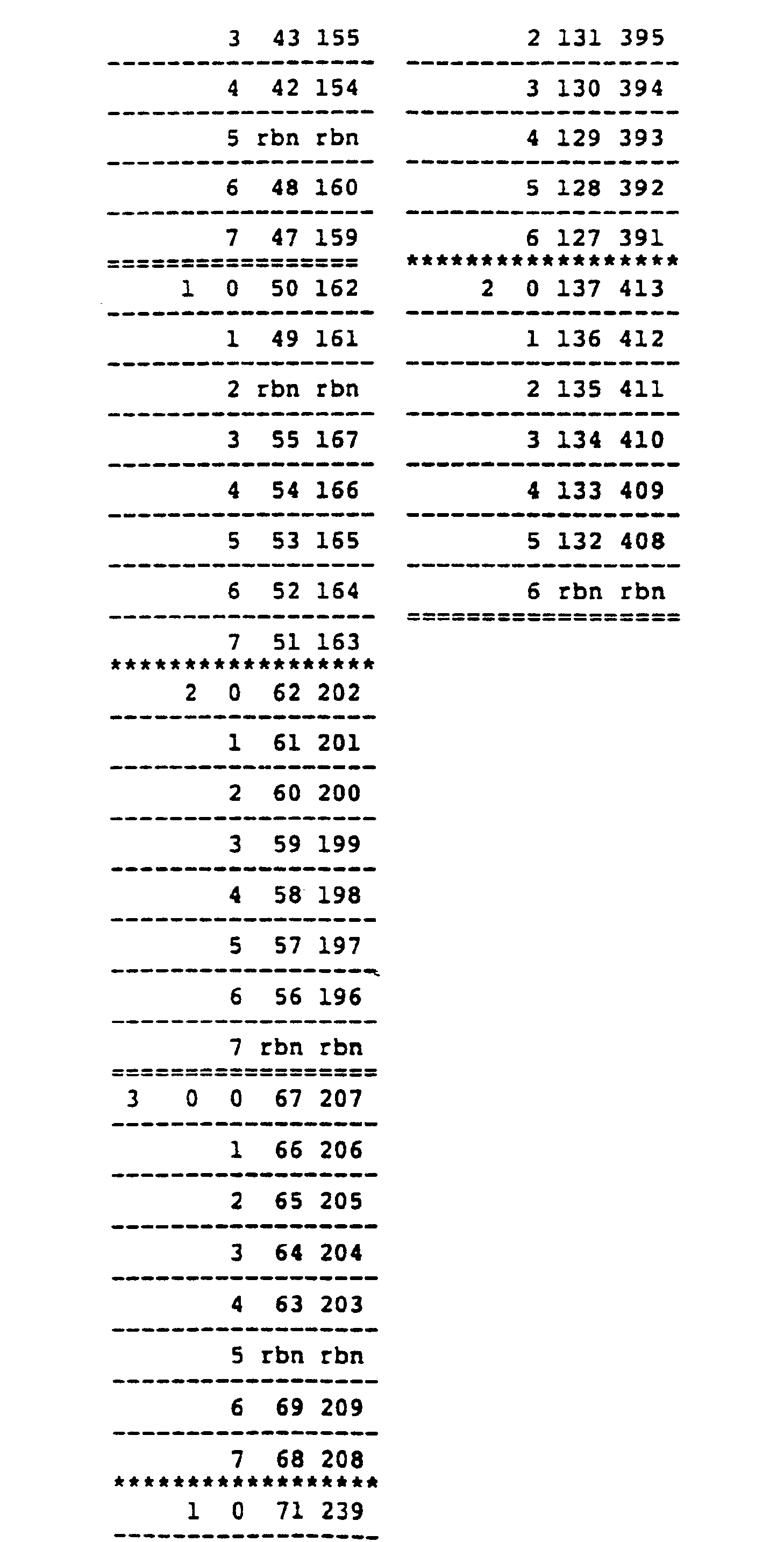
- Table 2 shows the arrangement of MBN's and LBN's suitable for a striped set of three of the disc drives 4 according to the parameters listed in Table 1.
- Each of the disc drives 4 have four bands on each of the discs 12, three of the heads 10 are used for storing data, and each of the disc drives 4 store 180 of the LBN's so that the striped set of three stores 540 of the LBN's.
- Table 2 is based upon a stripe chunk size of 2 tracks across all the bands. "Band 0", The outermost band with the greatest storage density, is arranged to have 8 sectors per track and 4 cylinders. With one sector “reserved” on each track for a replacement block number (RBN), 7 of the LBN's are thus assignable per track on Band 0.
- RBN replacement block number
- Band 1 the band inwardly adjacent to Band 0, has less storage density than Band 0. It is arranged to have three cylinders with 7 sectors per track. One of the sectors per track is reserved for an RBN, so six sectors per track are available for assignment to LBN's and MBN's in Band 1. Since each cylinder has three tracks, 54 of the sectors in Band 1 are assignable to LBN's and MBN's for each of the disc drives 4, allowing 162 sectors in Band 1 that are assignable to LBN's and MBN's for the entire striped set. Table 2 also provides for a sector offset of 3 sectors on Band 1 to account for head switch offset within Band 1.
- Band 2 the band inwardly adjacent to Band 1, has less storage density than Band 1. It is arranged to have 2 cylinders with six sectors per track. One of the sectors per track is reserved for an RBN, so five sectors per track are available for assignment to LBN's and MBN's in Band 2. Since each cylinder has three tracks, 30 of the sectors in Band 2 are assignable to LBN's and MBN's for each of the disc drives 4, allowing 90 sectors in Band 2 that are assignable to LBN's and MBN's for the entire striped set. Table 1 also indicates a sector offset of 2 sectors on Band 2 to account for head switch offset within Band 2.
- Band 3 the innermost band, has less storage density than any of the others. It is arranged to have only one cylinder in its band with five sectors per track. One of the sectors per track is reserved for an RBN, so four sectors per track are available for assignment to LBN's and MBN's in Band 3. Since the cylinder for Band 3 has three tracks, 12 of the sectors in Band 3 are assignable to LBN's and MBN's for each of the disc drives 4, allowing 36 sectors in Band 3 that are assignable to LBN's and MBN's for the entire striped set. Table 1 also indicates a sector offset of one sector on Band 3 to account for head switch offset within Band 3.
- the MBN's are assigned in one-on-one correspondence with the sectors in reverse order starting with the single cylinder, cylinder 0, and head 2, the highest of the heads 10, for each of the disc drives 4 listed in Table 1. Since each of the disc drives 4 arranged in this configuration store 180 of the MBN's, ranging from MBN 0 to MBN 179, MBN 179 is assigned to Sector 0 of Track 2 in the Cylinder 0 of Band 3. Track 2 corresponds to the highest head 10 of the Drive 2 in Table 1. Likewise, Track 1 corresponds to the head 10 of the Drive 2 immediately below Track 2, and Track 0 corresponds to the lowest head 10 of the Drive 2 immediately below Track 1.
- Track 2 of Cylinder 0 of Band 3 has 5 sectors, 4 of the sectors are available for storage of MBN's and one sector for an RBN. Therefore, MBN 179 through MBN 176 are stored in Sector 0 through Sector 3 respectively, and the RBN for this track is assigned to the immediately following Sector 4.
- Band 3 has an offset of one sector between tracks, so that MBN 175 is assigned to the sector in Track 1 following the one immediately after Sector 3 in Track 2 that stores MBN 176.
- Sector 0 through Sector 3 of Track 1 in Cylinder 0 of Band 3 are assigned with MBN 175 through MBN 172 respectively, with an RBN assigned to Sector 4.
- Sector 0 through Sector 3 of Track 0 in Cylinder 0 of Band 3 are assigned with MBN 171 through MBN 168 respectively, with an RBN assigned to Sector 4.
- the RBN's For Tracks 2, 1 and 0 are conveniently positioned on the sectors within the offset of the sectors assigned to the MBN's so that no increased access time occurs due to inclusion of the RBN's. Likewise, the RBN's are also arranged this way on the other bands as well.
- sector offsets may be used for seeks to improve spiral transfers comprising large numbers of sequential LBN's at one time.
- the use of sector offsets is a design decision, and not part of the present invention.
- the embodiment of the present invention herein described does not use sector offsets for the seeking operation although it is within the scope of the present invention to do so.
- MBN 167 continues on a different cylinder, a seeking operation is involved. Therefore, because a sector offsetforthe seeking operation is not used for this embodiment, MBN 167 is arbitrarily assigned to Sector 0 of Band 2. Thus, MBN 167 through MBN 163 are assigned to Sector 0 through 4 respectively, and an RBN is assigned to Sector 5.
- MBN 162 is assigned to Sector 1 of Track 1 in Cylinder 1 of Band 2. In this way MBN 162 through MBN 158 are assigned to Sector 1 through Sector 5 respectively, with an RBN assigned to Sector 0. Because of the two sector offset, MBN 157 is assigned to Sector2 of Track 0 in Cylinder 1 of Band 2. MBN 157 through MBN 153 are thus assigned to Sector 2 through Sector 5 and then Sector 0 respectively, and an RBN is assigned to Sector 1.
- MBN 152 is arbitrarily assigned to Sector 0 of Track 2 in Cylinder 0 of Band 2, since a seek operation between cylinders occurs and the two sector offset in Band 2 thus does not apply.
- MBN 152 through 148 are thus assigned to Sector 0 through Sector 4, and an RBN is assigned to Sector 5.
- MBN 147 is assigned to Sector 1 of Track 1 in Cylinder 0 of Band 2.
- MBN 147 through MBN 143 is assigned to Sector 1 through Sector 5, with an RBN assigned to Sector 0.
- MBN 142 is assigned to Sector 2 of Track 0 in Cylinder 0 to account for the two sector offset in Band 2 between Track 1 and Track 0.
- MBN 142 through MBN 138 are thus assigned to Sector 2 through Sector 5 and Sector 0, respectively, with an RBN assigned to Sector 1.
- the other disc drives 4 listed as Drive 1 and Drive 0 in Table 2 have their MBN's assigned the same way, so that their MBN's are all assigned to the same respective sectors as Drive 2. If the disc drives 4 listed in Table 2 are arranged in an unstriped set, then the corresponding LBN's can be assigned on a one-on-one basis with the MBN's, so that LBN 539 is assigned to the same sector of the same track in the same cylinder of the same band as MBN 179 on Drive 2. In this case, LBN 359 is assigned to the same sector of the same track in the same cylinder of the same band as MBN 179 in Drive 1 and LBN 179 is assigned to the same sector of the same track in the same cylinder of the same band as MBN 179 in Drive 0.
- LBN's shown in Table 2 for the disc drives 4 listed as Drive 2, Drive 1 and Drive 0 is for a striped set of the drives with a stripe chunk size of two tracks.
- the LBN's are arranged with LBN 539 assigned to the same sector of the same track in the same cylinder of the same band as MBN 179 in Drive 2. Since MBN 179 is assigned to Sector 0 of Track 2 in Cylinder 0 of Band 3, this MBN is assigned in a . short stripe. of Cylinder 0.
- LBN 539 through LBN 536 are thus consecutively assigned to Sector 0 through Sector 3 in Track 2 of Cylinder 0 in Band 3 of Drive 2, and an RBN is assigned to Sector 4. Because this track in Band 3 is a short stripe, LBN 535 is assigned to the sector in the track of the cylinder of the band in Drive 1 corresponding to MBN 179. LBN 535 through LBN 532 are thus consecutively assigned to Sector 0 through Sector 3 of Track 2 in Cylinder 0 of Band 3 in Drive 1, and an RBN is assigned to Sector 4.
- LBN 531 is assigned to the sector in the track of the cylinder of the band in Drive 0 corresponding to MBN 179. LBN 531 through LBN 528 are thus consecutively assigned to Sector 0 through Sector 3 of Track 2 in Cylinder 0 of Band 3 in Drive 0, and an RBN is assigned to Sector 4.
- LBN 527 is assigned to the next stripe in the set, which is the full stripe in Band 3 starting with Track 1 in Cylinder 0.
- LBN 527 is arbitrarily assigned to Sector 0 of Track 1 so that LBN 527 through LBN 524 are consecutively assigned to Sector 0 through Sector 3, with an RBN assigned to Sector 4.
- LBN 523 is assigned to Sector 0 of Track 0 in Cylinder 0 of Band 3 to account for the one sector offset in Band 3.
- LBN 523 through LBN 520 are consecutively assigned to Sector 0 through Sector 3 of Track 0 in Cylinder 0 of Band 3, with an RBN assigned to Sector 4.
- LBN 519 is assigned to the next full stripe, which starts with Track 1 in Cylinder 0 of Band 3 in Drive 1.
- LBN 519 is arbitrarily assigned to Sector 0 so that LBN 519 through LBN 516 are consecutively assigned to Sector 0 through Sector 3 of Track 1 in Cylinder 0 of Band 3, with an RBN assigned to Sector 4.
- LBN 515 is assigned to Sector 0 of Track 0 in Cylinder 0 of Band 3 to account for the one sector offset in Band 3.
- LBN 515 through LBN 512 are consecutively assigned to Sector 0 through Sector 3 of Track 0 in Cylinder 0 of Band 3, with an RBN assigned to Sector 4.
- LBN 511 is assigned to the next full stripe, which starts with Track 1 in Cylinder 0 of Band 3 in Drive 0.
- LBN 511 is arbitrarily assigned to Sector 0 so that LBN 511 through LBN 508 are consecutively assigned to Sector 0 through Sector 3 of Track 1 in Cylinder 0 of Band 3, with an RBN assigned to Sector 4.
- LBN 507 is assigned to Sector 0 of Track 0 in Cylinder 0 of Band 3 to account for the one sector offset in Band 3.
- LBN 507 through LBN 504 are consecutively assigned to Sector 0 through Sector 3 of Track 0 in Cylinder 0 of Band 3, with an RBN assigned to Sector 4.
- the present invention can be applied to any numberof disc drives 4 in a striped set or an unstriped set, with any number of tracks in any number of cylinders in any number of bands.
- the above-described embodiment represents only a simple implementation of logical block mapping according to the present invention.
- the disc drive controller 6 is easily programmed to implement the present invention for any combination of sets of the disc drives 4, either striped or unstriped.
- the following code is an example of programming suitable for this purpose in a striped set that functions with any combination of disc drive set size, disc drive storage density, stripe chunk size and number of bands.
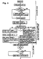
- Figure 5 is a flow chart ofthe LBN mapping algorithm according to the present invention implementing this code.
- the disc drive controller6 first calculates the unit band number and the offset into the band with the following code:
- the disc drive controller 6 checks for the short stripe condition and determines the drive number with the following code:
- the disc drive controller 6 then calculates the MBN with the following code:
- the disc drive controller 6 then calculates the physical cylinder, track and sector numbers with the following code:
- the code for an unstriped set of the disc drives 4 is the same, except that there are no stripe calculations and the LBN's map one-to-one with the MBN's.
- the normal read operation for a requested LBN automatically stores LBN's immediately subsequent the requested LBN during the read latentcy period because these LBN's are read before'the requested LBN is found. For instance, in the example described above, if LBN 42 is requested, Track 2 in Cylinder 0 of Band 0 in Drive 0 is read. If the head 10 corresponding to this track lands on the associated disc at Sector 0 of Track 0, Sectors 0 through 6 must be read during the read latency period because LBN 42 is in Sector 6.
Landscapes
- Engineering & Computer Science (AREA)
- Theoretical Computer Science (AREA)
- Physics & Mathematics (AREA)
- General Engineering & Computer Science (AREA)
- General Physics & Mathematics (AREA)
- Human Computer Interaction (AREA)
- Signal Processing For Digital Recording And Reproducing (AREA)
- Memory System Of A Hierarchy Structure (AREA)
Abstract
Description
- The present invention relates to logical block mapping of logical data blocks on disc type data storage systems, and more particularly to methods and apparatus for logical block to physical sector mapping and access to optimize prefetch caching with disc type data storage systems.
- Modem data processing systems generally use magnetic disc storage systems for storing therein an operating system program and data. Such a disc storage system may comprise an array of disc drives, with each disc drive having a plurality of discs and associated magnetic heads for each of the two magnetic surfaces of each disc.
- "Caching" of logical data blocks retrieved from the disc drive array is often done to improve the average access time of the disc drive array to requests for logical data blocks from the host data processing system. Caching is a technique that puts a small, fast memory, called a cache memory, in front of a large, slow memory, such as the disc drive array, in such a way that the resulting combination approximates a large, fast memory.
- "Prefetch blocks. are the logical data blocks that the host system has not requested, but are read from the discs in the array into the cache memory because a high probability exists that the host will request them in the near future. In this way, the stored prefetch blocks are available from the cache memory in response to a subsequent request from the host without reaccessing the disc drive array.
- Logical block numbers (LBN's) provide a means for the host system to address physical data on the disc drives without having to be concerned with the physical attributes of the disc drives. The logical data blocks are stored in the disc drive address with a physical block location that is mapped to correspond to a drive, band, cylinder, sector address in the array. A cylinder is made up of all of the tracks that can be accessed in the array without the need for a seek. For instance, if the disc drive array has five discs so that the array can access ten disc surfaces, it will typically have ten heads. The ten tracks that align beneath those heads at one time make up a cylinder.
- A read operation can be viewed as a three step process. The first step is to perform a wseek7 operation to move the heads to the correct cylinder. The second step is to waitforthe disk to rotate around so that the requested LBN passes under the head. This time is termed "rotational latency." The final step is to read the requested LBN as it passes under the head. Because of the sequential way that user processes for the host system access many files, and the policies that operating systems in the data processing systems use to allocate files, there is a tendency for the disc drive array to first see a request for a set of logical data blocks and then shortly after see a request for another set of logical data blocks starting with the block whose LBN is one greater than the last LBN of the first requested set of logical blocks.
- To best utilize the capabilities of the cache memory, it is therefore important to prefetch the logical blocks whose LBNs are greater (by a small amount) than the last logical blocks retrieved by a current request from the host. Traditional block ordering schemes order the LBN's so as to pass under the head in increasing order. When combined with read-ahead caching, these strategies require the heads to stay locked on the cylinder after the desired logical blocks have been read in order to access the read-ahead blocks. This is time that could otherwise be used to begin satisfying subsequent requests.
- The present invention overcomes the above-described limitation of the prior art block ordering scheme by placing the logical blocks on the tracks of the discs in the array in reverse order so that the logical blocks that have a high probability of being read in the near future can be read into cache memory during the otherwise "wasted" rotational latentcy period. The present invention also further increases performance by combining reverse ordered blocks with banding, striping, and compensation for sequential accesses across head switches.
-
- Figure 1 is a block diagram of a typical data processing system with a plurality of magnetic disc drives suitable for incorporating the present invention.
- Figure 2 is a disc drive for the data processing system shown in Figure 1.
- Figure 3 is a flow chart of the methodology of the logical block mapping according to the present invention for a striped set of three disc drives.
- Figure 4 is a schematic diagram of a banded disc surface configuration according to the prior art for which logical data blocks are arranged according to the present invention.
- Figure 5 is a flow chart of a LBN mapping algorithm according to the present invention.
- The present invention optimizes prefetch caching efficiency of disc drive type storage systems by reverse ordering the LBN's when they are stored on the disc surfaces and between discs so that LBN's that immediately follow the number of a requested LBN are automatically stored in the disc drive cache memory during the rotational latency period. During the rotational latency period, a number of LBN's are read before the requested LBN is found. With the reverse ordering scheme, the LBN's that are read before the requested LBN is found are those LBN's that immediately follow the requested LBN in number. By storing these LBN's in the disc drive cache as they are read, these LBN's are then available from the cache for subsequent LBN requests without performing another read operation.
- Referring to the drawings, wherein like characters designate like or corresponding parts throughout the views, Figure 1 shows a block diagram of a typical host
data processing system 2 that includes a plurality ofmagnetic disc drives 4. Thedisc drives 4 are coupled to thehost system 2 via adisc drive controller 6. Thehost 2 and thecontroller 6 are shown only in block form in Figure 1 because they are well known components of data processing systems that do not themselves constitute the present invention. - Each of the
disc drives 4 have the basic elements shown in detail in Figure 2. Normally, each of thedisc drives 4 respond to a LBN requested by thehost 2 via thecontroller 6 so as to cause an actuator arm 8 in thedisc drive 4 to move a set ofmagnetic heads 10 relative to a corresponding set ofmagnetic discs 12 to a physical cylinder position corresponding to the cylinder address mapped from the LBN. Thedisc drive 4 in Figure 2 is shown with a set of 10 of themagnetic heads 10 and a corresponding set of 5 of thediscs 12, although a greater or lesser number of theheads 10 can be used with a corresponding greater or lesser number of thediscs 12, as well known in the art. - The
disc drives 4 may utilize banding to improve their LBN storage density. The bands comprise different annular areas of the surfaces of thediscs 12 that are each written with a different bit frequency that is proportional to the surface velocities of the respective band to maximize the storage density of thedisc drive 4. This is because thediscs 12 rotate with a constant angular velocity and can support a constant bit density, so that a track with a large radius can support a higher bit frequency than a track with a small radius. - When a system contains a plurality of the
disc drives 4, it can be advantageous to "stripe" input/output (I/O) requests. Striping is the dispersion of a single 1/0 request across multiple disc drives of a disc drive storage system. A "stripe sef consists of two or more disc drives in a disc drive system, with the entire set being presented as a single logical volume for I/O. - The present invention uses striping primarily to statistically balance the I/O request load among the plurality of
discs 12 being striped, rather than leave such load balancing to higher-level system components, or manual management techniques. The logical blocks that are presented for I/O are spread across the disc in "chunks". These chunks have a size that may be measured in number of sectors, tracks, cylinders, bands, or even drives. For example, if the chunk size is 10 tracks, thentracks 0 through 9 are on a first one of thedisc drives 4,tracks 10 through 19 are on a second, and so forth. - Such banding and striping of the
disc drives 4 presents special problems to reverse ordering the way the LBN's are stored on thediscs drives 4 so thatthe LBN's are retrieved with optimal prefetch caching. The striping of UO requests is problematical for stripe chunk sizes that are not evenly divisible into the number of cylinders in the bands. For instance, if thedisc drives 4 each have a band with 3 cylinders and a stripe chunk size of 2 cylinders, then only one stripe chunk fits into the band with one cylinder remaining unassigned to a stripe. - According to the present invention, .short stripes. are the partial chunks left over at the end of a band when the stripe chunk size does not divide evenly into the number of cylinders in the band. Such short stripes allow the 1/0 requests to be switched between bands and the disc drives 4 when the bands are exhausted before a whole stripe chunk size has been filled. For instance, in the above described example of the discs drives 4 having a band with 3 cylinders and a stripe chunk size of two cylinders, the remaining cylinder is used as a short stripe and the striping procedure is modified to integrate the short stripes with the other stripes on the bands of the
disc drives 4. The short stripes allow each of the disc drives 4 to handle the optimum stripe chunk size without the complication of stripe chunks that cross band borders. - To assist in the reverse ordering of the logical blocks between the
different disc drives 4 including striping of the bands and short stripes, media block numbers (MBN's) are used. According to the present invention, the media block numbers (MBN's) are numbers that are used to map the LBN's to physical sectors on the disc surfaces in the disc drive array. MBN's map to sectors of thedisc drives 4 in a stripe set the way that LBN's normally map to sectors in anunstriped disc drive 4. - The MBN's identify the physical block location of the sectors for each of the disc drives independently of the stripe set used. This allows the drive to be logically addressed without concern as to whether it is in a striped or unstriped configuration. Mapping a LBN to a sector on a striped set of disc drives involves first determining which drive it is, then determining the MBN on that drive, and finally mapping from the MBN to the sector. The MBN's allow each of the
disc drives 4 in the stripe set to be treated as an unstriped drive, thus removing the burden of handling striping at the drive level. - If an u nstriped set of the
disc drives 4 is used, the LBN's can be directly assigned to the disc drives in reverse order, mapped one-to-one with the MBN's. Thedisc drive controller 6 maps the LBN's to sectors on respective tracks such that there is a one-to-one correspondence. For instance, if a particular track has 8 sectors, LBN 8 is assigned toSector 1, and each consecutively decreasing LBN is assigned to a consecutively increasing sector untilLBN 1 is assigned to Sector 8. - In this way, physical sectors on the track are written in normal order, but logically they are in reverse order, such that the first sector after the track index is
Sector 1, assigned with LBN 8. When a seek operation is performed on the track to retrieveLBN 4 onSector 6 and reading begins at Sector 3 with LBN 7, for instance, then the LBN's read from Sector 3 up toSector 6, LBN 7,LBN 6, and LBN 5, may be stored in the prefetch cache of the associateddisc drive 4. These LBN's may then be retrieved from the prefetch cache if they are sought on subsequent requests. - According to the present invention, the arrangement of the LBN's may be selected to place the highest LBN's in the tracks for the lowest or the
highest heads 10 of the disc drives 4. In the embodiment of the present invention described herein, the LBN's are arranged so that the highest LBN's are in the tracks for thehighest heads 10 of the disc drives 4. This arrangement allows the most efficient access to the reverse ordered LBN's. - However, between the different tracks for each cylinder it is also necessary to arrange the LBN's so that head switch offset is compensated for when the LBN's are retrieved with the reverse ordering scheme. Otherwise, the LBN's that immediately follow the last LBN in reverse order after track switching cannot be retrieved until a subsequent disc revolution.
- If a striped set of the
disc drives 4 is used, the MBN's are assigned to the sectors of each track of each cylinder of each of the disc drives 4. The MBN's are assigned to each of the sectors with a one-to-one correspondence, and with the MBN's of each of thedisc drives 4 having the same arrangement. In this way, the MBN's map the same sectors of the same tracks of the same cylinders for each of the disc drives 4. - Figure 3 is a flow chart of the methodology of the LBN and MBN assignment process with striping according to the present invention. The parameters of the striped set of the
disc drives 4 are first determined. These parameters include the numberof thedisc drives 4 in the set, the number of bands per drive, the number of cylinders per band for each band, the number of tracks per cylinder, and the stripe chunk size. In this embodiment, the stripe chunk size is shown by number of tracks. - The boundaries of the full stripes are then determined without crossing band boundaries. According to the present invention, the ordering of the stripes is not important In the embodiment described herein, the full stripe boundaries are assigned starting from the lowest track in the outer cylinder of the outermost band and terminating at the highest track of the inner cylinder of the innermost band. Those tracks of cylinders at the end of each band that are too small in number to fit into a full stripe are not assigned to a full stripe.
- The boundaries of short stripes are then determined without crossing band boundaries. The short stripe boundaries are assigned to the tracks of the cylinders between the assigned full stripes in the same order of assignment as the full stripes.
- MBN's are then sequentially assigned in reverse order on each of the
disc drives 4 in the striped set from the top track of the outer cylinder of the innermost band to the bottom track of the innermost cylinder of the outermost band. The assignment of the MBN's is confined to each disc drive. In this way, each of the disc drives in the set have the same range and placement of MBN's. - LBN's are then assigned to consecutive "chunks" of MBN's across the disc drives. For example, if each chunk contains 14 MBN's, LBN's 0 to 13 are assigned to MBN's 0 to 13 on the first one of the
disc drives 4 in the striped set, LBN's 14 to 27 are assigned to MBN's 0 to 13 on the second one of thedisc drives 4 in the striped set, and so forth. - Table 1 shows the parameters determined for a striped set of three of the disc drives 4. These parameters include a stripe chunk size of two tracks, three tracks per cylinder, and four bands. The number of LBN's and MBN's per track, the number of sectors per track, the sector offset, the number of cylinders per band and the number of LBN's or MBN's per band are also listed.
- Figure 4 shows the band and sector configuration for the surface of each of the
discs 12 in thedisc drives 4 having the parameters listed in Table 1. Thedisc 12 is shown with 4 bands on its surface, with each of the bands divided into a different number of sectors conforming to the different storage density of each band. The outermost band of thedisc 12 shown in Figure 4 is "Band 0".Band 0 has 8 sectors per track in each of its 4 cylinders. The band inwardlyadjacent Band 0 is "Band 1 ".Band 1 has 7 sectors per track in each of its 3 cylinders. The band inwardlyadjacent Band 1 is "Band 2".Band 2 has 6 sectors per track in each of its two cylinders. The band inwardlyadjacent Band 2 is "Band 3". Band 3 has 5 sectors on its single cylinder. All bands have 3 tracks per cylinder. The configuration of thedisc 12 shown in Figure 4 is according to the prior art and it is not itself part of the present invention. - Table 2 shows the arrangement of MBN's and LBN's suitable for a striped set of three of the
disc drives 4 according to the parameters listed in Table 1. Each of thedisc drives 4 have four bands on each of thediscs 12, three of theheads 10 are used for storing data, and each of thedisc drives 4 store 180 of the LBN's so that the striped set of three stores 540 of the LBN's. - In addition, Table 2 is based upon a stripe chunk size of 2 tracks across all the bands. "
Band 0", The outermost band with the greatest storage density, is arranged to have 8 sectors per track and 4 cylinders. With one sector "reserved" on each track for a replacement block number (RBN), 7 of the LBN's are thus assignable per track onBand 0. - Since there are three tracks per cylinder for each of the
disc drives 4, there are 84 sectors inBand 0 that are assignable to LBN's and MBN's for each of thedisc drives 4, allowing 252 sectors inBand 0 that are assignable to LBN's and MBN's for the entire striped set. Table 1 also provides for a sector offset of 4 sectors onBand 0 to account for head switch offset withinBand 0. The sector offset is arranged for the reverse ordering of the LBN's. - "
Band 1", the band inwardly adjacent to Band 0, has less storage density thanBand 0. It is arranged to have three cylinders with 7 sectors per track. One of the sectors per track is reserved for an RBN, so six sectors per track are available for assignment to LBN's and MBN's inBand 1. Since each cylinder has three tracks, 54 of the sectors inBand 1 are assignable to LBN's and MBN's for each of thedisc drives 4, allowing 162 sectors inBand 1 that are assignable to LBN's and MBN's for the entire striped set. Table 2 also provides for a sector offset of 3 sectors onBand 1 to account for head switch offset withinBand 1. - "
Band 2", the band inwardly adjacent to Band 1, has less storage density thanBand 1. It is arranged to have 2 cylinders with six sectors per track. One of the sectors per track is reserved for an RBN, so five sectors per track are available for assignment to LBN's and MBN's inBand 2. Since each cylinder has three tracks, 30 of the sectors inBand 2 are assignable to LBN's and MBN's for each of thedisc drives 4, allowing 90 sectors inBand 2 that are assignable to LBN's and MBN's for the entire striped set. Table 1 also indicates a sector offset of 2 sectors onBand 2 to account for head switch offset withinBand 2. - "Band 3", the innermost band, has less storage density than any of the others. It is arranged to have only one cylinder in its band with five sectors per track. One of the sectors per track is reserved for an RBN, so four sectors per track are available for assignment to LBN's and MBN's in Band 3. Since the cylinder for Band 3 has three tracks, 12 of the sectors in Band 3 are assignable to LBN's and MBN's for each of the
disc drives 4, allowing 36 sectors in Band 3 that are assignable to LBN's and MBN's for the entire striped set. Table 1 also indicates a sector offset of one sector on Band 3 to account for head switch offset within Band 3. - The MBN's are assigned in one-on-one correspondence with the sectors in reverse order starting with the single cylinder,
cylinder 0, andhead 2, the highest of theheads 10, for each of thedisc drives 4 listed in Table 1. Since each of thedisc drives 4 arranged in this configuration store 180 of the MBN's, ranging fromMBN 0 to MBN 179, MBN 179 is assigned toSector 0 ofTrack 2 in theCylinder 0 of Band 3.Track 2 corresponds to thehighest head 10 of theDrive 2 in Table 1. Likewise,Track 1 corresponds to thehead 10 of theDrive 2 immediately belowTrack 2, andTrack 0 corresponds to thelowest head 10 of theDrive 2 immediately belowTrack 1. - Since
Track 2 ofCylinder 0 of Band 3 has 5 sectors, 4 of the sectors are available for storage of MBN's and one sector for an RBN. Therefore, MBN 179 through MBN 176 are stored inSector 0 through Sector 3 respectively, and the RBN for this track is assigned to the immediately followingSector 4. - Band 3 has an offset of one sector between tracks, so that MBN 175 is assigned to the sector in
Track 1 following the one immediately after Sector 3 inTrack 2 that stores MBN 176. Thus,Sector 0 through Sector 3 ofTrack 1 inCylinder 0 of Band 3 are assigned with MBN 175 through MBN 172 respectively, with an RBN assigned toSector 4. Likewise,Sector 0 through Sector 3 ofTrack 0 inCylinder 0 of Band 3 are assigned with MBN 171 through MBN 168 respectively, with an RBN assigned toSector 4. - It should be noted that the RBN's For
Tracks - The MBN's are continued on
Band 2 ofDrive 2 starting with the inner cylinder,Cylinder 1, onTrack 2. It should be noted that head switch offset is not defined between cylinders, either of the same or different bands. This is because a seek operation is always involved for theheads 10 that interrupts the track switching operation. Because of the period of the seek operation and its variability, any assignment of sector offset due to the seek operation between cylinders is a rough approximation at best - However, such sector offsets may be used for seeks to improve spiral transfers comprising large numbers of sequential LBN's at one time. The use of sector offsets is a design decision, and not part of the present invention. The embodiment of the present invention herein described does not use sector offsets for the seeking operation although it is within the scope of the present invention to do so.
- Since MBN 167 continues on a different cylinder, a seeking operation is involved. Therefore, because a sector offsetforthe seeking operation is not used for this embodiment, MBN 167 is arbitrarily assigned to
Sector 0 ofBand 2. Thus, MBN 167 through MBN 163 are assigned toSector 0 through 4 respectively, and an RBN is assigned to Sector 5. - Because of the two sector offset between
Track 2 andTrack 1 inBand 2, MBN 162 is assigned toSector 1 ofTrack 1 inCylinder 1 ofBand 2. In this way MBN 162 through MBN 158 are assigned toSector 1 through Sector 5 respectively, with an RBN assigned toSector 0. Because of the two sector offset, MBN 157 is assigned to Sector2 ofTrack 0 inCylinder 1 ofBand 2. MBN 157 through MBN 153 are thus assigned toSector 2 through Sector 5 and thenSector 0 respectively, and an RBN is assigned toSector 1. - MBN 152 is arbitrarily assigned to
Sector 0 ofTrack 2 inCylinder 0 ofBand 2, since a seek operation between cylinders occurs and the two sector offset inBand 2 thus does not apply. MBN 152 through 148 are thus assigned toSector 0 throughSector 4, and an RBN is assigned to Sector 5. Because of the two sector offset betweenTrack 2 andTrack 1 inBand 2, MBN 147 is assigned toSector 1 ofTrack 1 inCylinder 0 ofBand 2. In this way MBN 147 through MBN 143 is assigned toSector 1 through Sector 5, with an RBN assigned toSector 0. - Similarly, MBN 142 is assigned to
Sector 2 ofTrack 0 inCylinder 0 to account for the two sector offset inBand 2 betweenTrack 1 andTrack 0. MBN 142 through MBN 138 are thus assigned toSector 2 through Sector 5 andSector 0, respectively, with an RBN assigned toSector 1. - Assignment of the MBN's from band to band, cylinder to cylinder and track to track continues in this way until
MBN 0 is assigned toSector 4 inTrack 0 ofCylinder 0 ofBand 0 according to Table 1. As explained above, whenever the assignment ofthe MBN's switches fromTrack 0 of one cylinder to Track 2 of another, assignment of the MBN's with a sector offset does not apply. In this case, the assignment of the MBN's is arbitrarily established to continue withSector 0 ofTrack 2 in the following cylinder, just as described above. - The
other disc drives 4 listed asDrive 1 and Drive 0 in Table 2 have their MBN's assigned the same way, so that their MBN's are all assigned to the same respective sectors asDrive 2. If thedisc drives 4 listed in Table 2 are arranged in an unstriped set, then the corresponding LBN's can be assigned on a one-on-one basis with the MBN's, so that LBN 539 is assigned to the same sector of the same track in the same cylinder of the same band as MBN 179 onDrive 2. In this case, LBN 359 is assigned to the same sector of the same track in the same cylinder of the same band as MBN 179 inDrive 1 and LBN 179 is assigned to the same sector of the same track in the same cylinder of the same band as MBN 179 inDrive 0. - However, arrangement of the LBN's shown in Table 2 for the
disc drives 4 listed asDrive 2, Drive 1 and Drive 0 is for a striped set of the drives with a stripe chunk size of two tracks. As with an unstriped set, the LBN's are arranged with LBN 539 assigned to the same sector of the same track in the same cylinder of the same band as MBN 179 inDrive 2. Since MBN 179 is assigned toSector 0 ofTrack 2 inCylinder 0 of Band 3, this MBN is assigned in a .short stripe. ofCylinder 0. - This is because the stripe chunk size is two tracks, and Band three only has three tracks. As arranged in Table 2, one stripe extends from
Track 0 throughTrack 1 ofCylinder 0 in Band 3. Therefore,Track 2 ofCylinder 0 in Band 3 is a short stripe of only one track, since Band 3 only has one cylinder and stripes cannot extend across band boundaries, intoBand 2, for instance. - LBN 539 through LBN 536 are thus consecutively assigned to
Sector 0 through Sector 3 inTrack 2 ofCylinder 0 in Band 3 ofDrive 2, and an RBN is assigned toSector 4. Because this track in Band 3 is a short stripe, LBN 535 is assigned to the sector in the track of the cylinder of the band inDrive 1 corresponding to MBN 179. LBN 535 through LBN 532 are thus consecutively assigned toSector 0 through Sector 3 ofTrack 2 inCylinder 0 of Band 3 inDrive 1, and an RBN is assigned toSector 4. - Since
Track 2 ofCylinder 0 of Band 3 inDrive 1 is also a short stripe, LBN 531 is assigned to the sector in the track of the cylinder of the band inDrive 0 corresponding to MBN 179. LBN 531 through LBN 528 are thus consecutively assigned toSector 0 through Sector 3 ofTrack 2 inCylinder 0 of Band 3 inDrive 0, and an RBN is assigned toSector 4. - Since
Track 2 ofCylinder 0 of Band 3 inDrive 0 is also a short stripe, LBN 527 is assigned to the next stripe in the set, which is the full stripe in Band 3 starting withTrack 1 inCylinder 0. LBN 527 is arbitrarily assigned toSector 0 ofTrack 1 so that LBN 527 through LBN 524 are consecutively assigned toSector 0 through Sector 3, with an RBN assigned toSector 4. - Continuing in this full stripe, LBN 523 is assigned to
Sector 0 ofTrack 0 inCylinder 0 of Band 3 to account for the one sector offset in Band 3. Thus LBN 523 through LBN 520 are consecutively assigned toSector 0 through Sector 3 ofTrack 0 inCylinder 0 of Band 3, with an RBN assigned toSector 4. - LBN 519 is assigned to the next full stripe, which starts with
Track 1 inCylinder 0 of Band 3 inDrive 1. LBN 519 is arbitrarily assigned toSector 0 so that LBN 519 through LBN 516 are consecutively assigned toSector 0 through Sector 3 ofTrack 1 inCylinder 0 of Band 3, with an RBN assigned toSector 4. - Continuing in this full stripe, LBN 515 is assigned to
Sector 0 ofTrack 0 inCylinder 0 of Band 3 to account for the one sector offset in Band 3. Thus LBN 515 through LBN 512 are consecutively assigned toSector 0 through Sector 3 ofTrack 0 inCylinder 0 of Band 3, with an RBN assigned toSector 4. - LBN 511 is assigned to the next full stripe, which starts with
Track 1 inCylinder 0 of Band 3 inDrive 0. LBN 511 is arbitrarily assigned toSector 0 so that LBN 511 through LBN 508 are consecutively assigned toSector 0 through Sector 3 ofTrack 1 inCylinder 0 of Band 3, with an RBN assigned toSector 4. - Continuing in this full stripe, LBN 507 is assigned to
Sector 0 ofTrack 0 inCylinder 0 of Band 3 to account for the one sector offset in Band 3. Thus LBN 507 through LBN 504 are consecutively assigned toSector 0 through Sector 3 ofTrack 0 inCylinder 0 of Band 3, with an RBN assigned toSector 4. - The assignment of LBN 506 through
LBN 0 then continues in this way through the stripes sequentially fromDrive 2 through Drive onBand 2 throughBand 0. Short stripes onBands - Of course, the present invention can be applied to any
numberof disc drives 4 in a striped set or an unstriped set, with any number of tracks in any number of cylinders in any number of bands. The above-described embodiment represents only a simple implementation of logical block mapping according to the present invention. - The
disc drive controller 6 is easily programmed to implement the present invention for any combination of sets of thedisc drives 4, either striped or unstriped. The following code is an example of programming suitable for this purpose in a striped set that functions with any combination of disc drive set size, disc drive storage density, stripe chunk size and number of bands. Figure 5 is a flow chart ofthe LBN mapping algorithm according to the present invention implementing this code. - The following generic symbols are used in this code:
- b = band number for disc drive
- s(b) = sectors per track for band b
- t = tracks per cylinder for disc drive
- c(b) = cylinders per band for band b
- h = number of disc drives in a stripe set
- ch = number of tracks in a stripe chunk
- I(b) = LBN's per track for band b
- o(b) = sector offset per head switch for band b
- r = RBN's per track for disc drive
- d = disc drive number in a stripe set
- short_ch = tracks per chunk in a short stripe
- DIV = The Pascal integer division operator. The result is not rounded and it is truncated toward zero to the nearest integer.
- The disc drive controller6 first calculates the unit band number and the offset into the band with the following code:
- Cyl_offset(0) = 0
- U_)LBN_offset(0) = LBN
- U_LBN_offset(1) = U_LBN_offset(0) - h * c(o) * t * 1(0)
- if U_LBN_offset(1) < 0, b = 0, Check for short stripe
- Cy)_offset(1) = c(0)
- U_LBN_offset(2) = U_LBN_offset(1) - h * c(1) * t * 1(1)
- if U_LBN_offset(2) < 0, b = 1, Check for short stripe
- Cyl_offset(2) = c(0) + c(1)
- U_LBN_offset(3) = U_LBN_offset(2) - h * c(2) * t * 1 (2)
- if U_LBN_offset(last_band) < 0, b = 2, Check for short stripe
- (progression continues until last_band-1)
- Cyl_offset(last_band) = c(0) + c(1) + c(2)+_..+c(last_band-1)
- b = last band, Check for short stripe
- The
disc drive controller 6 checks for the short stripe condition and determines the drive number with the following code: - if U_LBN_offset(b) > ((c(b) * t) DIV ch) * ch * 1(b) * h
- (It is in a short stripe chunk)
- short_ch = (c(b) * t) MOD ch
- U_rem_offset = U_LBN_offset - (c(b) * t DIV ch) * ch *1 (b)
- d = U_rem_offset DIV short_ch
- MBN_offset(b) = (U_rem_offset MOD (short_ch *1(b)) + ((c(b) t) DIV ch) *ch * 1(b)
- else
- (It is not a short stripe)
- chunk_number = U_LBN_offset(b) DIV (ch * 1(b))
- d = chunk_number MOD h
- MBN_offset(b) = (U_LBN_offset(b) MOD (ch * 1(b)) + (chunk_number DIV h) * ch * 1(b)
- The
disc drive controller 6 then calculates the MBN with the following code: - MBN = MBN_offset(b)
- if b > 0 MBN = MBN + 1(0) * c(0) * t
- if b > 1 MBN = MBN + 1(1) * c(1) * t
- if b > 2 MBN = MBN + 1(2) * c(2) * t
- (progression continues until last band number - 1)
- The
disc drive controller 6 then calculates the physical cylinder, track and sector numbers with the following code: - Cylinder = MBN_offset(b) DIV (t * 1(b))
- Track = (MBN_offset(b) DIV 1(b)) MOD t
- Track offset= MBN_offset MOD 1(b)
- Inverted_track_offset = 1(b) - 1 - Track_offset
- Sector = (Inverted_track_offset + Sector_offset) MOD s(b)
- The code for an unstriped set of the
disc drives 4 is the same, except that there are no stripe calculations and the LBN's map one-to-one with the MBN's. - With the reverse ordered LBN's arranged as prescribed above, the normal read operation for a requested LBN automatically stores LBN's immediately subsequent the requested LBN during the read latentcy period because these LBN's are read before'the requested LBN is found. For instance, in the example described above, if LBN 42 is requested,
Track 2 inCylinder 0 ofBand 0 inDrive 0 is read. If thehead 10 corresponding to this track lands on the associated disc atSector 0 ofTrack 0,Sectors 0 through 6 must be read during the read latency period because LBN 42 is inSector 6. - Thus there has been described herein methods and apparatus for implementing reverse ordered logical block mapping in disc drive data storage sets to optimize prefetch caching. It will be understood that various changes in the details, arrangements and parts of the systems, as well as the steps of the processes, herein described and illustrated in order to explain the nature of the present invention may be made by those skilled in the art within the principle and scope of the invention as expressed in the appended daims.
- What is claimed is:



Claims (30)
Applications Claiming Priority (2)
| Application Number | Priority Date | Filing Date | Title |
|---|---|---|---|
| US07/509,037 US5283875A (en) | 1990-04-13 | 1990-04-13 | Method and apparatus for optimizing prefetch caching by reverse ordering of logical blocks |
| US509037 | 1990-04-13 |
Publications (3)
| Publication Number | Publication Date |
|---|---|
| EP0452019A2 true EP0452019A2 (en) | 1991-10-16 |
| EP0452019A3 EP0452019A3 (en) | 1992-02-26 |
| EP0452019B1 EP0452019B1 (en) | 1998-01-28 |
Family
ID=24025043
Family Applications (1)
| Application Number | Title | Priority Date | Filing Date |
|---|---|---|---|
| EP91302878A Expired - Lifetime EP0452019B1 (en) | 1990-04-13 | 1991-04-02 | Methods and apparatus for optimizing prefetch caching |
Country Status (5)
| Country | Link |
|---|---|
| US (1) | US5283875A (en) |
| EP (1) | EP0452019B1 (en) |
| JP (1) | JPH04227523A (en) |
| CA (1) | CA2039296A1 (en) |
| DE (1) | DE69128807T2 (en) |
Cited By (2)
| Publication number | Priority date | Publication date | Assignee | Title |
|---|---|---|---|---|
| EP0661639A1 (en) * | 1993-12-30 | 1995-07-05 | International Business Machines Corporation | Data prefetch in mass data storage systems |
| US10606754B2 (en) | 2012-04-16 | 2020-03-31 | International Business Machines Corporation | Loading a pre-fetch cache using a logical volume mapping |
Families Citing this family (38)
| Publication number | Priority date | Publication date | Assignee | Title |
|---|---|---|---|---|
| DE69131551T2 (en) * | 1990-11-09 | 2000-02-17 | Emc Corp., Hopkinton | Logical division of a storage system with redundant matrix |
| JP3575811B2 (en) * | 1992-05-07 | 2004-10-13 | 株式会社日立製作所 | Storage device |
| US5546557A (en) * | 1993-06-14 | 1996-08-13 | International Business Machines Corporation | System for storing and managing plural logical volumes in each of several physical volumes including automatically creating logical volumes in peripheral data storage subsystem |
| US5584007A (en) * | 1994-02-09 | 1996-12-10 | Ballard Synergy Corporation | Apparatus and method for discriminating among data to be stored in cache |
| US5588129A (en) * | 1994-02-09 | 1996-12-24 | Ballard; Clinton L. | Cache for optical storage device and method for implementing same |
| US5636368A (en) * | 1994-12-23 | 1997-06-03 | Xilinx, Inc. | Method for programming complex PLD having more than one function block type |
| US6072648A (en) * | 1997-08-14 | 2000-06-06 | Seagate Technology, Inc. | System and method for formatting disc surfaces |
| US6141728A (en) * | 1997-09-29 | 2000-10-31 | Quantum Corporation | Embedded cache manager |
| US6098114A (en) | 1997-11-14 | 2000-08-01 | 3Ware | Disk array system for processing and tracking the completion of I/O requests |
| US7107395B1 (en) * | 1998-12-31 | 2006-09-12 | Emc Corporation | Apparatus and methods for operating a computer storage system |
| TW573295B (en) | 1999-04-23 | 2004-01-21 | Koninkl Philips Electronics Nv | Apparatus and method for scanning a rotating information carrier |
| US6883066B2 (en) * | 2001-09-14 | 2005-04-19 | Seagate Technology Llc | Method and system for cache management algorithm selection |
| US6792504B2 (en) | 2002-01-25 | 2004-09-14 | Seagate Technology Llc | Read on arrival scheme for a disc drive |
| US20050166012A1 (en) * | 2004-01-26 | 2005-07-28 | Yong Liu | Method and system for cognitive pre-fetching |
| US10459892B2 (en) | 2014-04-23 | 2019-10-29 | Qumulo, Inc. | Filesystem hierarchical aggregate metrics |
| US11360936B2 (en) | 2018-06-08 | 2022-06-14 | Qumulo, Inc. | Managing per object snapshot coverage in filesystems |
| US10795796B1 (en) | 2020-01-24 | 2020-10-06 | Qumulo, Inc. | Predictive performance analysis for file systems |
| US11151001B2 (en) | 2020-01-28 | 2021-10-19 | Qumulo, Inc. | Recovery checkpoints for distributed file systems |
| CN111400976B (en) * | 2020-03-16 | 2022-05-06 | 天津水运工程勘察设计院有限公司 | Calculation Method of Influence of J-column on K-column Exciting Force in Cylindrical Array under Wave Action |
| US11775481B2 (en) | 2020-09-30 | 2023-10-03 | Qumulo, Inc. | User interfaces for managing distributed file systems |
| US11157458B1 (en) | 2021-01-28 | 2021-10-26 | Qumulo, Inc. | Replicating files in distributed file systems using object-based data storage |
| US11461241B2 (en) | 2021-03-03 | 2022-10-04 | Qumulo, Inc. | Storage tier management for file systems |
| US11132126B1 (en) | 2021-03-16 | 2021-09-28 | Qumulo, Inc. | Backup services for distributed file systems in cloud computing environments |
| US11567660B2 (en) | 2021-03-16 | 2023-01-31 | Qumulo, Inc. | Managing cloud storage for distributed file systems |
| US11669255B2 (en) | 2021-06-30 | 2023-06-06 | Qumulo, Inc. | Distributed resource caching by reallocation of storage caching using tokens and agents with non-depleted cache allocations |
| US11354273B1 (en) * | 2021-11-18 | 2022-06-07 | Qumulo, Inc. | Managing usable storage space in distributed file systems |
| US11599508B1 (en) | 2022-01-31 | 2023-03-07 | Qumulo, Inc. | Integrating distributed file systems with object stores |
| US12346290B2 (en) | 2022-07-13 | 2025-07-01 | Qumulo, Inc. | Workload allocation for file system maintenance |
| US11722150B1 (en) | 2022-09-28 | 2023-08-08 | Qumulo, Inc. | Error resistant write-ahead log |
| US11729269B1 (en) | 2022-10-26 | 2023-08-15 | Qumulo, Inc. | Bandwidth management in distributed file systems |
| US11966592B1 (en) | 2022-11-29 | 2024-04-23 | Qumulo, Inc. | In-place erasure code transcoding for distributed file systems |
| US12292853B1 (en) | 2023-11-06 | 2025-05-06 | Qumulo, Inc. | Object-based storage with garbage collection and data consolidation |
| US11921677B1 (en) | 2023-11-07 | 2024-03-05 | Qumulo, Inc. | Sharing namespaces across file system clusters |
| US11934660B1 (en) | 2023-11-07 | 2024-03-19 | Qumulo, Inc. | Tiered data storage with ephemeral and persistent tiers |
| US12222903B1 (en) | 2024-08-09 | 2025-02-11 | Qumulo, Inc. | Global namespaces for distributed file systems |
| US12481625B1 (en) | 2024-11-12 | 2025-11-25 | Qumulo, Inc. | Integrating file system operations with network infrastructure |
| US12443568B1 (en) | 2024-11-12 | 2025-10-14 | Qumulo, Inc. | Verifying performance characteristics of network infrastructure for file systems |
| US12585563B1 (en) | 2025-12-01 | 2026-03-24 | Qumulo, Inc. | Caching for object stores |
Family Cites Families (10)
| Publication number | Priority date | Publication date | Assignee | Title |
|---|---|---|---|---|
| DE2853501A1 (en) * | 1978-12-12 | 1980-06-26 | Ibm Deutschland | STORAGE HIERARCHY WITH CHARGE SHIFT STORAGE |
| JPS5943786B2 (en) * | 1979-03-30 | 1984-10-24 | パナフアコム株式会社 | Storage device access method |
| EP0080878A3 (en) * | 1981-11-27 | 1985-06-26 | Storage Technology Corporation | Cache memory and method of control for use with magnetic disks |
| JPS59100964A (en) * | 1982-12-01 | 1984-06-11 | Hitachi Ltd | Parallel transfer type director device |
| US4607346A (en) * | 1983-03-28 | 1986-08-19 | International Business Machines Corporation | Apparatus and method for placing data on a partitioned direct access storage device |
| JPS61190638A (en) * | 1985-02-20 | 1986-08-25 | Hitachi Ltd | File control system for virtual computer |
| JP2636212B2 (en) * | 1985-05-27 | 1997-07-30 | 株式会社日立製作所 | Magnetic disk device |
| US4835686A (en) * | 1985-05-29 | 1989-05-30 | Kabushiki Kaisha Toshiba | Cache system adopting an LRU system, and magnetic disk controller incorporating it |
| US5113512A (en) * | 1988-06-21 | 1992-05-12 | Matsushita Electric Industrial Co., Ltd. | System for managing a storage medium reducing physical space needed |
| US5018095A (en) * | 1990-02-15 | 1991-05-21 | Seagate Technology, Inc. | Universal disk drive type emulation for IBM PC-AT computers |
-
1990
- 1990-04-13 US US07/509,037 patent/US5283875A/en not_active Expired - Lifetime
-
1991
- 1991-03-27 CA CA002039296A patent/CA2039296A1/en not_active Abandoned
- 1991-04-02 DE DE69128807T patent/DE69128807T2/en not_active Expired - Fee Related
- 1991-04-02 EP EP91302878A patent/EP0452019B1/en not_active Expired - Lifetime
- 1991-04-15 JP JP3082698A patent/JPH04227523A/en active Pending
Cited By (2)
| Publication number | Priority date | Publication date | Assignee | Title |
|---|---|---|---|---|
| EP0661639A1 (en) * | 1993-12-30 | 1995-07-05 | International Business Machines Corporation | Data prefetch in mass data storage systems |
| US10606754B2 (en) | 2012-04-16 | 2020-03-31 | International Business Machines Corporation | Loading a pre-fetch cache using a logical volume mapping |
Also Published As
| Publication number | Publication date |
|---|---|
| DE69128807D1 (en) | 1998-03-05 |
| EP0452019A3 (en) | 1992-02-26 |
| US5283875A (en) | 1994-02-01 |
| EP0452019B1 (en) | 1998-01-28 |
| JPH04227523A (en) | 1992-08-17 |
| DE69128807T2 (en) | 1998-06-18 |
| CA2039296A1 (en) | 1991-10-14 |
Similar Documents
| Publication | Publication Date | Title |
|---|---|---|
| EP0452019B1 (en) | Methods and apparatus for optimizing prefetch caching | |
| US5765204A (en) | Method and apparatus for adaptive localization of frequently accessed, randomly addressed data | |
| US5734861A (en) | Log-structured disk array with garbage collection regrouping of tracks to preserve seek affinity | |
| US6170037B1 (en) | Method and apparatus for storing information among a plurality of disk drives | |
| EP0686907B1 (en) | Memory system with hierarchic disk array and memory map store for persistent storage of virtual mapping information | |
| EP0726514B1 (en) | Methods for using non contiguously reserved storage space for data migration in a redundant hierarchic data storage system | |
| US5596736A (en) | Data transfers to a backing store of a dynamically mapped data storage system in which data has nonsequential logical addresses | |
| US4935825A (en) | Cylinder defect management system for data storage system | |
| EP0706113B1 (en) | Method for adding storage disks to a hierarchic disk array while maintaining data availability | |
| US5802344A (en) | Method and apparatus for dynamic segment allocation in log structured arrays | |
| US5664187A (en) | Method and system for selecting data for migration in a hierarchic data storage system using frequency distribution tables | |
| EP0801344B1 (en) | An apparatus for reallocating logical to physical disk devices using a storage controller and method of the same | |
| CA2375672C (en) | Disk drive controller circuit and method for skipping defective and/or undesired sectors | |
| KR100255081B1 (en) | Disk drive system and method for acessing a physical memory location therein | |
| US4974197A (en) | Batching data objects for recording on optical disks with maximum object count | |
| EP0639811A2 (en) | Memory systems with data storage redundancy management | |
| JPH08249134A (en) | Method for writing of user data according to redundancy parity storage technique | |
| KR20020064357A (en) | Buffer management system for managing the transfer of data into and out of a buffer in a disc drive | |
| JPH0877073A (en) | Collective optical disk device | |
| US5809295A (en) | Method and apparatus for storing compressed file data on a disk where each MDFAT data structure includes an extra byte | |
| CN1610876A (en) | Concurrent read and write access to simulated sequential data of a removable random access data storage medium | |
| JPH05216593A (en) | Indirect access storage device | |
| US5420983A (en) | Method for merging memory blocks, fetching associated disk chunk, merging memory blocks with the disk chunk, and writing the merged data | |
| JP2004272324A (en) | Disk array device | |
| WO1993000635A1 (en) | Data storage management systems |
Legal Events
| Date | Code | Title | Description |
|---|---|---|---|
| PUAI | Public reference made under article 153(3) epc to a published international application that has entered the european phase |
Free format text: ORIGINAL CODE: 0009012 |
|
| 17P | Request for examination filed |
Effective date: 19910412 |
|
| AK | Designated contracting states |
Kind code of ref document: A2 Designated state(s): DE FR GB IT NL |
|
| PUAL | Search report despatched |
Free format text: ORIGINAL CODE: 0009013 |
|
| AK | Designated contracting states |
Kind code of ref document: A3 Designated state(s): DE FR GB IT NL |
|
| RAP1 | Party data changed (applicant data changed or rights of an application transferred) |
Owner name: QUANTUM CORPORATION |
|
| 17Q | First examination report despatched |
Effective date: 19960821 |
|
| GRAG | Despatch of communication of intention to grant |
Free format text: ORIGINAL CODE: EPIDOS AGRA |
|
| GRAG | Despatch of communication of intention to grant |
Free format text: ORIGINAL CODE: EPIDOS AGRA |
|
| GRAH | Despatch of communication of intention to grant a patent |
Free format text: ORIGINAL CODE: EPIDOS IGRA |
|
| GRAH | Despatch of communication of intention to grant a patent |
Free format text: ORIGINAL CODE: EPIDOS IGRA |
|
| GRAA | (expected) grant |
Free format text: ORIGINAL CODE: 0009210 |
|
| AK | Designated contracting states |
Kind code of ref document: B1 Designated state(s): DE FR GB IT NL |
|
| REF | Corresponds to: |
Ref document number: 69128807 Country of ref document: DE Date of ref document: 19980305 |
|
| ITF | It: translation for a ep patent filed | ||
| ET | Fr: translation filed | ||
| PLBE | No opposition filed within time limit |
Free format text: ORIGINAL CODE: 0009261 |
|
| STAA | Information on the status of an ep patent application or granted ep patent |
Free format text: STATUS: NO OPPOSITION FILED WITHIN TIME LIMIT |
|
| 26N | No opposition filed | ||
| PGFP | Annual fee paid to national office [announced via postgrant information from national office to epo] |
Ref country code: FR Payment date: 19990317 Year of fee payment: 9 |
|
| PGFP | Annual fee paid to national office [announced via postgrant information from national office to epo] |
Ref country code: NL Payment date: 19990331 Year of fee payment: 9 |
|
| PG25 | Lapsed in a contracting state [announced via postgrant information from national office to epo] |
Ref country code: NL Free format text: LAPSE BECAUSE OF NON-PAYMENT OF DUE FEES Effective date: 20001101 |
|
| PG25 | Lapsed in a contracting state [announced via postgrant information from national office to epo] |
Ref country code: FR Free format text: LAPSE BECAUSE OF NON-PAYMENT OF DUE FEES Effective date: 20001229 |
|
| NLV4 | Nl: lapsed or anulled due to non-payment of the annual fee |
Effective date: 20001101 |
|
| REG | Reference to a national code |
Ref country code: FR Ref legal event code: ST |
|
| PGFP | Annual fee paid to national office [announced via postgrant information from national office to epo] |
Ref country code: DE Payment date: 20010320 Year of fee payment: 11 |
|
| PGFP | Annual fee paid to national office [announced via postgrant information from national office to epo] |
Ref country code: GB Payment date: 20010321 Year of fee payment: 11 |
|
| REG | Reference to a national code |
Ref country code: GB Ref legal event code: IF02 |
|
| PG25 | Lapsed in a contracting state [announced via postgrant information from national office to epo] |
Ref country code: GB Free format text: LAPSE BECAUSE OF NON-PAYMENT OF DUE FEES Effective date: 20020402 |
|
| PG25 | Lapsed in a contracting state [announced via postgrant information from national office to epo] |
Ref country code: DE Free format text: LAPSE BECAUSE OF NON-PAYMENT OF DUE FEES Effective date: 20021101 |
|
| GBPC | Gb: european patent ceased through non-payment of renewal fee |
Effective date: 20020402 |
|
| PG25 | Lapsed in a contracting state [announced via postgrant information from national office to epo] |
Ref country code: IT Free format text: LAPSE BECAUSE OF NON-PAYMENT OF DUE FEES;WARNING: LAPSES OF ITALIAN PATENTS WITH EFFECTIVE DATE BEFORE 2007 MAY HAVE OCCURRED AT ANY TIME BEFORE 2007. THE CORRECT EFFECTIVE DATE MAY BE DIFFERENT FROM THE ONE RECORDED. Effective date: 20050402 |