EP0452058B1 - Angle d'attaque d'un élément rapporté pour trépan de roche à rouleaux coniques - Google Patents
Angle d'attaque d'un élément rapporté pour trépan de roche à rouleaux coniques Download PDFInfo
- Publication number
- EP0452058B1 EP0452058B1 EP91303056A EP91303056A EP0452058B1 EP 0452058 B1 EP0452058 B1 EP 0452058B1 EP 91303056 A EP91303056 A EP 91303056A EP 91303056 A EP91303056 A EP 91303056A EP 0452058 B1 EP0452058 B1 EP 0452058B1
- Authority
- EP
- European Patent Office
- Prior art keywords
- inserts
- insert
- rock bit
- cone
- rotary cone
- Prior art date
- Legal status (The legal status is an assumption and is not a legal conclusion. Google has not performed a legal analysis and makes no representation as to the accuracy of the status listed.)
- Expired - Lifetime
Links
Images

Classifications
-
- E—FIXED CONSTRUCTIONS
- E21—EARTH OR ROCK DRILLING; MINING
- E21B—EARTH OR ROCK DRILLING; OBTAINING OIL, GAS, WATER, SOLUBLE OR MELTABLE MATERIALS OR A SLURRY OF MINERALS FROM WELLS
- E21B10/00—Drill bits
- E21B10/08—Roller bits
- E21B10/16—Roller bits characterised by tooth form or arrangement
Definitions
- This invention relates to roller cone rock bits with tungsten carbide inserts inserted within insert holes formed within the body of the roller cones.
- this invention relates to the attack angle of each of the tungsten carbide inserts retained within a cone.
- Each of the inserts has an attack angle with respect to a borehole formation that assures that the insert is primarily in a compressive mode upon initial contact with the formation, and the insert introduces more scraping and shearing to the earthen formation.
- roller cone prior art that teaches the use of tungsten carbide inserts pressed into roller cones has the centre line of the tungsten carbide inserts intersecting an axis of the cone. Hence the inserts are generally 90° with respect to a face of the frustoconical cone with the center line of the insert passing through the axial center line of the cone and rock bit journal. Roller cones where the center line of the inserts is offset from the axial center line of the cones are also known (GB-A-2009817).
- U.S. Patent No. 3,743,038 teaches an improved drill bit tooth of a milled tooth rotary cone bit having a leading tooth face, i.e. the face first contacting the formation being cut, substantially parallel with an axis of rotation of the drill bit cone.
- the trailing face of the milled tooth is convexly shaped to act as a fulcrum. This tooth configuration allows the tooth to get under and lift a chip from the formation being cut rather than sliding it to the side.
- the leading face of each of the milled teeth intersects an axial center line of the cone.
- the present invention orients each of the tungsten carbide inserts such that the inserts have an attack angle with respect to a formation.
- the center line of the insert does not intersect the axial center line of each of the cones.
- U.S. Patent No. 3,763,942 teaches a large mechanically driven auger or boring head designed especially for horizontal rock and earth drilling of mines or tunnels.
- the boring head defines a circular ring of circumferentially spaced tool bits or teeth.
- the cutting teeth on the ring of the body of the bit project radially outwardly from the peripheral surface of the ring and are tilted forwardly in the direction of rotation of the auger head.
- the cutting teeth on the body of the bit project forwardly and tilt toward the direction of rotation of the cutting head and are also tilted backwardly to present the tip end of each tooth in a straight forward direction to the surface in which it is cutting.
- the teeth are staggered so that successive teeth will not have the same cutting track.
- the present invention differs in that it is for a rotary cone rock bit wherein each of the tungsten carbide inserts are angled such that they are positioned approximately axially relative to an earthen formation at initial contact. Each of the inserts, therefore, is in a more compressive mode rather than in shear as the insert first contacts the bottom of a borehole.
- U.S. Patent No. 4,415,208 is yet another mining bit having individual cutters mounted to a mechanically driven ring for the tunnel cutter.
- This patent deals with a means of mounting the insert.
- the cutter bit assembly has an elongated cutter element, a bit holder, a bit block and locking means for removably affixing the bit holder to the bit block.
- the bit holder has a tapered locking lip and a tapered surface wherein a resulting cutting force provides a locking action against the taper.
- each of the cutters is not in a true compressive mode as the cutter attacks a formation.
- the present invention provides a roller cone bit wherein the cones roll on a formation bottom with a heavy weight driving the cones into the formation, each of the inserts being angled to assure that the inserts are in a compressive mode upon first contact rather than a shear mode during the cutting operation.
- U.S. Patent No. 4,108,260 describes roller cone rock bits with specially shaped inserts.
- the inserts used for cutter teeth of rock bits used in drilling soft and medium formations of the earth are generally chisel shaped with the flanks converging to a crest.
- the flanks of the inserts of the present invention are asymmetrical with respect to each other.
- the leading flank is scoop-shaped and the trailing flank is rounded outwardly.
- the center line of each of the inserts pass through an axial center line of the roller cone.
- the present invention has a center line of each of the inserts that does not intersect the axial center line of the roller cone, each of the inserts being angled to insure that the insert is primarily in compression upon initial contact with the formation.
- each of the inserts has an orientation that is primarily 90° to a surface of the roller cones, the center line of the asymmetrical inserts intersecting the axial center line of the cone.
- a rotary cone rock bit having multiple cutter inserts imbedded in insert holes formed in a body of the cone, said multiple cutter inserts generally being equidistantly spaced apart and arranged in circumferential rows along the axis of said cone, the center line of each insert and respective insert hole being angularly offset, by an attack angle ⁇ , from a radial line defined between the cone axis and the intersection of the insert center line and the outside surface of the insert, characterised in that each of the inserts is directed toward the direction of rotation of the cone and the attack angle is such that, each of the inserts is primarily in compression upon initial contact with the borehole formation.
- An advantage then of the present invention over the prior art is the angular orientation of inserts embedded in a rotary cone, each of the inserts having an attack angle that initially subjects each insert to compressive modes resulting in less bending and hence less breakage of the insert during initial contact of the insert with an earthen formation.
- the aggressive attack angle of the inserts results in more shearing, scraping and peeling of the formation during operation of a rotary cone rock bit in a borehole.
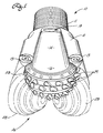
- the rotary cone rock bit generally designated as 10 comprises a rock bit body 12 with a pin end 11 and cutting end generally designated as 26.
- Each cone 28 associated with cutting end 26 is rotatably mounted on a journal bearing extending from a leg 14 that terminates in a shirttail portion 16.
- Each of the cones 28, for example, has a multiplicity of substantially equally spaced inserts 29 interference fitted within insert holes 27 formed in the cone body 28 (Fig. 6).
- a lubricant reservoir generally designated as 18 is provided in each of the legs 14 to supply lubricant to bearing surfaces formed between the rotary cones and their respective journals.
- Three or more nozzles 13 communicate with a chamber formed within the bit body 12 (not shown).
- the chamber receives drilling fluid or "mud" through the pin end 11 and the fluid is directed out through the nozzles 13 during bit operation.
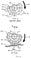
- a rotary cone 34 has embedded within the cone body, a multiplicity of tungsten carbide inserts 36.
- the inserts 36 have, for example, conical cutting ends 39.
- An axis 37 of each of the inserts 36 passes through a cone axis 38.
- Each of the inserts is about normal to a surface 33 of the cone 34.
- the rotation of the cone typically is in the direction 35, however it should be noted that with the orientation of the inserts in the cone 34 normal to a surface of the cone 33 it would not matter which direction the cone was rotated.
- a cone 28 is shown in contact with an earthen formation 20.
- Each of the inserts 29 interference fitted within an insert retention hole 27 (Fig. 6) is illustrated with an attack angle represented as ⁇ .
- Angle ⁇ is defined between an axis 30 of the insert 29 and a radial line 24 defined between an axis 25 of the cone through a point at the intersection of the insert axis 30 and insert profile. This angle ⁇ may be between 0° and 45°.
- the cone rotation 19 subjects each of the inserts 29 oriented in the direction of rotation of the cone to a compressive load as the inserts 29 initially contact the earthen formation 20.
- FIGURE 4 illustrates a single angled insert 29.
- the ⁇ attack angle in the example shown is 30° (angle 31).
- the maximum angulation for ⁇ is shown by ⁇ angle 32 and is 45°.
- the amount of angulation for ⁇ in a particular row depends on the equidistant spacing from insert to insert in a row.
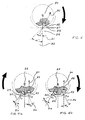
- FIGURES 5a and 5b illustrate schematically the preferred attack angulation from insert to insert.
- the angle ⁇ 3 is greater than angle ⁇ 2 because of the further spacing from C1 to C3 as compared to C1 to C2. If the spacing between inserts in a single circumferential row is close then the angle ⁇ is less between each of the equidistantly spaced inserts in that particular row. In another row, if the inserts are spaced further apart around that circumferential row then the angle ⁇ is greater as illustrated by angle ⁇ 3.
- the attack angle is greater in ⁇ 3 than ⁇ 2 because C3 is further from C1 than C2 is from C1.
- the orientation of angle ⁇ is shown in four separate circumferential rows of inserts, for example, the row of inserts 29 nearest the apex 21 of the cone 28 in FIGURE 6 illustrates the insert center line 30 exactly parallel with center line 43 of the rock bit 10.
- the inserts 29 in the row nearest the heel 22 of the rock bit cone 28 are less parallel with center line 43 due to the material limitation of the cone.
- the insert retention hole 27 is angled to provide enough cone material to securely retain the insert 29 within its insert retention hole 27.
- the intermediate rows are at intermediate angles from the axis of the bit.
- the inserts 29 are additionally oriented to align the center line of each of the inserts as nearly parallel to the center line 43 of the rock bit 10 as is possible.
- the angle ⁇ is defined between the axis 30 of the insert 29 and a line 44 parallel to the bit axis 43 through a point at the intersection of the axis 30 of the insert 29 and the insert profile.
- the angle ⁇ is preferably within the range of ⁇ max angles defined between the center line 25 of the cone 28 and a line 41 perpendicular to the bit axis 43.
- the angle ⁇ defined by the axis 30 of the insert 29 should be as nearly parallel with the center line 43 of the rock bit 10 as feasible; that is, the angle ⁇ should be as small as possible.
- each of the inserts 29 are subjected to compressive loads rather than shear loads as the cone rotates against a borehole bottom.
- the inserts are subjected to more out thrust loading as opposed to in thrust loading.
- inserts other than symmetrical frustoconical inserts.
- chisel type or asymmetric type inserts common within the rock bit industry may be utilized
Landscapes
- Engineering & Computer Science (AREA)
- Geology (AREA)
- Mining & Mineral Resources (AREA)
- Life Sciences & Earth Sciences (AREA)
- General Life Sciences & Earth Sciences (AREA)
- Fluid Mechanics (AREA)
- Mechanical Engineering (AREA)
- Environmental & Geological Engineering (AREA)
- Physics & Mathematics (AREA)
- Geochemistry & Mineralogy (AREA)
- Earth Drilling (AREA)
- Display Devices Of Pinball Game Machines (AREA)
- Toys (AREA)
- Pharmaceuticals Containing Other Organic And Inorganic Compounds (AREA)
- Rolls And Other Rotary Bodies (AREA)
Claims (9)
- Trépan de roche (10) à rouleaux coniques (28) présentant chacun une pluralité d'inserts de coupe (29) encastrés dans des trous d'insert (27) formés dans le corps du rouleau conique, lesdits inserts de cette pluralité d'inserts de coupe étant disposés en étant essentiellement équidistants entre eux et agencés en rangées circonférentielles selon l'axe (25) dudit rouleau conique, l'axe central (30) de chaque insert du trou d'insert associé étant décalé angulairement, selon un angle d'attaque (α), par rapport à une ligne radiale (24) allant de l'axe (25) du rouleau conique au point d'intersection entre l'axe central de l'insert et la surface extérieure dudit insert, caractérisé en ce que chacun des inserts est dirigé vers la direction de rotation du rouleau conique, et l'angle d'attaque est tel que chaque insert est principalement soumis à une compression lors du Contact initial avec le trou de forage en formation.
- Trépan de roche à rouleaux coniques selon la revendication 1, caractérisé en ce que l'angle d'attaque (α) est compris entre 0° et 45°, et en ce que la valeur de cet angle croît lorsque l'écartement entre inserts adjacents d'une rangée circonférentielle augmente, et décroît lorsque l'écartement entre inserts adjacents d'une rangée circonférentielle diminue.
- Trépan de roche à rouleaux coniques selon l'une quelconque des revendications précédentes, caractérisé en ce que, lorsqu'il est au point le plus bas de sa rotation, l'axe central (30) de chaque insert (29) est orienté sensiblement parallèlement à l'axe (43) dudit trépan de roche à rouleaux coniques, de façon que la charge exercée sur le trépan dans une direction qui est perpendiculaire au trou en formation en train d'être foré, soumette chaque insert à des efforts maximums de compression et des efforts minimums de cisaillement lors du travail du trépan dans ce trou en formation.
- Trépan de roche à rouleaux coniques selon l'une quelconque des revendications précédentes, caractérisé en ce que l'angle (β) formé par l'axe central (30) de l'insert et l'axe (43) du trépan de roche ne dépasse pas l'angle (βmax) formé par l'axe (25) du rouleau conique et un plan perpendiculaire à l'axe (43) du trépan de roche.
- Trépan de roche à rouleaux coniques selon la revendication 4, caractérisé en ce que l'angle (α) et l'angle (β) de chacun des inserts équidistants entre eux dans les rangées circonférentielles sont orientés de telle façon que chaque insert soit soumis à des efforts maximums de compression et des efforts minimums de cisaillement lorsque ledit trépan de roche à rouleaux coniques travaille pour forer un trou.
- Trépan de roche à rouleaux coniques selon l'une quelconque des revendications précédentes, caractérisé en ce que les inserts de coupe sont des inserts en carbure de tungstène.
- Trépan de roche à rouleaux coniques selon l'une quelconque des revendications précédentes, caractérisé en ce que les inserts de coupe sont en carbure de tungstène et sont en forme de tronc de cône de révolution.
- Trépan de roche à rouleaux coniques selon l'une quelconque des revendications précédentes, caractérisé en ce que les inserts sont des inserts du type à taillant simple.
- Trépan de roche à rouleaux coniques selon l'une quelconque des revendications précédentes, caractérisé en ce que les inserts sont des inserts asymétriques.
Applications Claiming Priority (2)
| Application Number | Priority Date | Filing Date | Title |
|---|---|---|---|
| US07/507,827 US5027913A (en) | 1990-04-12 | 1990-04-12 | Insert attack angle for roller cone rock bits |
| US507827 | 1990-04-12 |
Publications (3)
| Publication Number | Publication Date |
|---|---|
| EP0452058A2 EP0452058A2 (fr) | 1991-10-16 |
| EP0452058A3 EP0452058A3 (en) | 1992-07-01 |
| EP0452058B1 true EP0452058B1 (fr) | 1995-10-25 |
Family
ID=24020298
Family Applications (1)
| Application Number | Title | Priority Date | Filing Date |
|---|---|---|---|
| EP91303056A Expired - Lifetime EP0452058B1 (fr) | 1990-04-12 | 1991-04-08 | Angle d'attaque d'un élément rapporté pour trépan de roche à rouleaux coniques |
Country Status (5)
| Country | Link |
|---|---|
| US (1) | US5027913A (fr) |
| EP (1) | EP0452058B1 (fr) |
| AT (1) | ATE129542T1 (fr) |
| DE (1) | DE69114040D1 (fr) |
| NO (1) | NO911387L (fr) |
Families Citing this family (19)
| Publication number | Priority date | Publication date | Assignee | Title |
|---|---|---|---|---|
| US5407022A (en) * | 1993-11-24 | 1995-04-18 | Baker Hughes Incorporated | Free cutting gage insert with relief angle |
| US6390210B1 (en) * | 1996-04-10 | 2002-05-21 | Smith International, Inc. | Rolling cone bit with gage and off-gage cutter elements positioned to separate sidewall and bottom hole cutting duty |
| US5813485A (en) * | 1996-06-21 | 1998-09-29 | Smith International, Inc. | Cutter element adapted to withstand tensile stress |
| US5839526A (en) * | 1997-04-04 | 1998-11-24 | Smith International, Inc. | Rolling cone steel tooth bit with enhancements in cutter shape and placement |
| US5868213A (en) * | 1997-04-04 | 1999-02-09 | Smith International, Inc. | Steel tooth cutter element with gage facing knee |
| US6029759A (en) * | 1997-04-04 | 2000-02-29 | Smith International, Inc. | Hardfacing on steel tooth cutter element |
| US7334652B2 (en) * | 1998-08-31 | 2008-02-26 | Halliburton Energy Services, Inc. | Roller cone drill bits with enhanced cutting elements and cutting structures |
| US6167833B1 (en) * | 1998-10-30 | 2001-01-02 | Camco International Inc. | Wear indicator for rotary drilling tools |
| US6095264A (en) * | 1999-01-22 | 2000-08-01 | Camco International, Inc. | Rolling cutter drill bit with stabilized insert holes and method for making a rolling cutter drill bit with stabilized insert holes |
| US20060074616A1 (en) * | 2004-03-02 | 2006-04-06 | Halliburton Energy Services, Inc. | Roller cone drill bits with optimized cutting zones, load zones, stress zones and wear zones for increased drilling life and methods |
| US7360612B2 (en) * | 2004-08-16 | 2008-04-22 | Halliburton Energy Services, Inc. | Roller cone drill bits with optimized bearing structures |
| US7434632B2 (en) * | 2004-03-02 | 2008-10-14 | Halliburton Energy Services, Inc. | Roller cone drill bits with enhanced drilling stability and extended life of associated bearings and seals |
| US20090229888A1 (en) * | 2005-08-08 | 2009-09-17 | Shilin Chen | Methods and systems for designing and/or selecting drilling equipment using predictions of rotary drill bit walk |
| WO2007019472A1 (fr) | 2005-08-08 | 2007-02-15 | Halliburton Energy Services, Inc. | Procedes et systemes de conception et/ou de selection d'equipement de forage reposant sur des simulations de forage de puits |
| US7860693B2 (en) * | 2005-08-08 | 2010-12-28 | Halliburton Energy Services, Inc. | Methods and systems for designing and/or selecting drilling equipment using predictions of rotary drill bit walk |
| WO2009079371A1 (fr) * | 2007-12-14 | 2009-06-25 | Halliburton Energy Services, Inc. | Procédés et systèmes de prédiction du pas d'un trépan rotatif et de conception de trépans rotatifs et d'autres outils de fond de trou |
| US8281881B2 (en) * | 2008-03-11 | 2012-10-09 | Smith International, Inc. | Rolling cone drill bit having cutting elements with improved orientations |
| US8733475B2 (en) | 2011-01-28 | 2014-05-27 | National Oilwell DHT, L.P. | Drill bit with enhanced hydraulics and erosion-shield cutting teeth |
| CN102364030B (zh) * | 2011-08-26 | 2015-05-13 | 四川深远石油钻井工具股份有限公司 | 旋切方式破岩的钻头 |
Family Cites Families (11)
| Publication number | Priority date | Publication date | Assignee | Title |
|---|---|---|---|---|
| US2038386A (en) * | 1935-03-09 | 1936-04-21 | Hughes Tool Co | Cutter for well drills |
| US3385385A (en) * | 1966-04-01 | 1968-05-28 | Reed Roller Bit Co | Drill bit |
| FR1568146A (fr) * | 1967-06-06 | 1969-05-23 | ||
| US3743038A (en) * | 1971-11-23 | 1973-07-03 | Sun Oil Co | Drill bit |
| US3763942A (en) * | 1972-02-25 | 1973-10-09 | Contracting & Material Co | Auger head |
| US4108260A (en) * | 1977-04-01 | 1978-08-22 | Hughes Tool Company | Rock bit with specially shaped inserts |
| US4161225A (en) * | 1977-12-07 | 1979-07-17 | Dresser Industries, Inc. | Skewed inserts for an earth boring cutter |
| US4187922A (en) * | 1978-05-12 | 1980-02-12 | Dresser Industries, Inc. | Varied pitch rotary rock bit |
| US4415208A (en) * | 1981-07-31 | 1983-11-15 | Ingersoll-Rand Company | Cutter bit assembly |
| SE457656B (sv) * | 1984-06-18 | 1989-01-16 | Santrade Ltd | Borrkrona innefattande en roterande skaerrulle och borrhuvud innefattande saadan borrkrona |
| US4751972A (en) * | 1986-03-13 | 1988-06-21 | Smith International, Inc. | Revolving cutters for rock bits |
-
1990
- 1990-04-12 US US07/507,827 patent/US5027913A/en not_active Expired - Lifetime
-
1991
- 1991-04-08 DE DE69114040T patent/DE69114040D1/de not_active Expired - Lifetime
- 1991-04-08 AT AT91303056T patent/ATE129542T1/de not_active IP Right Cessation
- 1991-04-08 EP EP91303056A patent/EP0452058B1/fr not_active Expired - Lifetime
- 1991-04-10 NO NO91911387A patent/NO911387L/no unknown
Also Published As
| Publication number | Publication date |
|---|---|
| DE69114040D1 (de) | 1995-11-30 |
| US5027913A (en) | 1991-07-02 |
| ATE129542T1 (de) | 1995-11-15 |
| EP0452058A2 (fr) | 1991-10-16 |
| NO911387L (no) | 1991-10-14 |
| NO911387D0 (no) | 1991-04-10 |
| EP0452058A3 (en) | 1992-07-01 |
Similar Documents
| Publication | Publication Date | Title |
|---|---|---|
| US5027913A (en) | Insert attack angle for roller cone rock bits | |
| EP0467870B1 (fr) | Trépan à molettes dentées avec éléments de coupe rapportés périphériques | |
| US5813485A (en) | Cutter element adapted to withstand tensile stress | |
| CA2288923C (fr) | Outils de coupe a fort decentrage avec lames superabrasives | |
| US4334586A (en) | Inserts for drilling bits | |
| US5341890A (en) | Ultra hard insert cutters for heel row rotary cone rock bit applications | |
| US6367569B1 (en) | Replaceable multiple TCI kerf ring | |
| US4872520A (en) | Flat bottom drilling bit with polycrystalline cutters | |
| US4838366A (en) | Drill bit | |
| CA1266651A (fr) | Outil a mises de coupe pour la foration dans le roc | |
| US5407022A (en) | Free cutting gage insert with relief angle | |
| US5458210A (en) | Drill bits and blades therefor | |
| US4393948A (en) | Rock boring bit with novel teeth and geometry | |
| EP0584255B1 (fr) | Outils rotatifs pour exploitation miniere | |
| CA1214159A (fr) | Trepan de forage et organe de coupe perfectionne | |
| EP0395572A1 (fr) | Trépan bicône avec cônes non opposés | |
| US7624825B2 (en) | Drill bit and cutter element having aggressive leading side | |
| US20080121435A1 (en) | Single cone rock bit having inserts adapted to maintain hole gage during drilling | |
| US4813501A (en) | Rotary mining bit | |
| US7025155B1 (en) | Rock bit with channel structure for retaining cutter segments | |
| US4917196A (en) | Excavating tooth for an earth auger | |
| US4202419A (en) | Roller cutter with major and minor insert rows | |
| US5735360A (en) | Mining bit | |
| US8281881B2 (en) | Rolling cone drill bit having cutting elements with improved orientations | |
| US6044919A (en) | Rotary spade drill arrangement |
Legal Events
| Date | Code | Title | Description |
|---|---|---|---|
| PUAI | Public reference made under article 153(3) epc to a published international application that has entered the european phase |
Free format text: ORIGINAL CODE: 0009012 |
|
| AK | Designated contracting states |
Kind code of ref document: A2 Designated state(s): AT DE FR GB IT SE |
|
| PUAL | Search report despatched |
Free format text: ORIGINAL CODE: 0009013 |
|
| AK | Designated contracting states |
Kind code of ref document: A3 Designated state(s): AT DE FR GB IT SE |
|
| 17P | Request for examination filed |
Effective date: 19921229 |
|
| 17Q | First examination report despatched |
Effective date: 19940218 |
|
| GRAA | (expected) grant |
Free format text: ORIGINAL CODE: 0009210 |
|
| AK | Designated contracting states |
Kind code of ref document: B1 Designated state(s): AT DE FR GB IT SE |
|
| PG25 | Lapsed in a contracting state [announced via postgrant information from national office to epo] |
Ref country code: IT Free format text: LAPSE BECAUSE OF FAILURE TO SUBMIT A TRANSLATION OF THE DESCRIPTION OR TO PAY THE FEE WITHIN THE PRE;WARNING: LAPSES OF ITALIAN PATENTS WITH EFFECTIVE DATE BEFORE 2007 MAY HAVE OCCURRED AT ANY TIME BEFORE 2007. THE CORRECT EFFECTIVE DATE MAY BE DIFFERENT FROM THE ONE RECORDED.SCRIBED TIME-LIMIT Effective date: 19951025 Ref country code: FR Effective date: 19951025 Ref country code: AT Effective date: 19951025 |
|
| REF | Corresponds to: |
Ref document number: 129542 Country of ref document: AT Date of ref document: 19951115 Kind code of ref document: T |
|
| REF | Corresponds to: |
Ref document number: 69114040 Country of ref document: DE Date of ref document: 19951130 |
|
| PG25 | Lapsed in a contracting state [announced via postgrant information from national office to epo] |
Ref country code: SE Effective date: 19960125 |
|
| PG25 | Lapsed in a contracting state [announced via postgrant information from national office to epo] |
Ref country code: DE Effective date: 19960126 |
|
| EN | Fr: translation not filed | ||
| PLBE | No opposition filed within time limit |
Free format text: ORIGINAL CODE: 0009261 |
|
| STAA | Information on the status of an ep patent application or granted ep patent |
Free format text: STATUS: NO OPPOSITION FILED WITHIN TIME LIMIT |
|
| 26N | No opposition filed | ||
| REG | Reference to a national code |
Ref country code: GB Ref legal event code: IF02 |
|
| PGFP | Annual fee paid to national office [announced via postgrant information from national office to epo] |
Ref country code: GB Payment date: 20070425 Year of fee payment: 17 |
|
| GBPC | Gb: european patent ceased through non-payment of renewal fee |
Effective date: 20080408 |
|
| PG25 | Lapsed in a contracting state [announced via postgrant information from national office to epo] |
Ref country code: GB Free format text: LAPSE BECAUSE OF NON-PAYMENT OF DUE FEES Effective date: 20080408 |