EP0452073A2 - Schaltkreis zum Abschalten einer Batterie - Google Patents
Schaltkreis zum Abschalten einer Batterie Download PDFInfo
- Publication number
- EP0452073A2 EP0452073A2 EP91303087A EP91303087A EP0452073A2 EP 0452073 A2 EP0452073 A2 EP 0452073A2 EP 91303087 A EP91303087 A EP 91303087A EP 91303087 A EP91303087 A EP 91303087A EP 0452073 A2 EP0452073 A2 EP 0452073A2
- Authority
- EP
- European Patent Office
- Prior art keywords
- circuit
- ride
- over
- relay coil
- battery
- Prior art date
- Legal status (The legal status is an assumption and is not a legal conclusion. Google has not performed a legal analysis and makes no representation as to the accuracy of the status listed.)
- Withdrawn
Links
Images
Classifications
-
- H—ELECTRICITY
- H02—GENERATION; CONVERSION OR DISTRIBUTION OF ELECTRIC POWER
- H02J—ELECTRIC POWER NETWORKS; CIRCUIT ARRANGEMENTS OR SYSTEMS FOR SUPPLYING OR DISTRIBUTING ELECTRIC POWER; SYSTEMS FOR STORING ELECTRIC ENERGY
- H02J7/00—Circuit arrangements for charging or discharging batteries or for supplying loads from batteries
- H02J7/60—Circuit arrangements for charging or discharging batteries or for supplying loads from batteries including safety or protection arrangements
- H02J7/663—Circuit arrangements for charging or discharging batteries or for supplying loads from batteries including safety or protection arrangements using battery or load disconnect circuits
- H02J7/667—Circuit arrangements for charging or discharging batteries or for supplying loads from batteries including safety or protection arrangements using battery or load disconnect circuits disconnection of loads if battery is not under charge, e.g. in vehicle if engine is not running
-
- Y—GENERAL TAGGING OF NEW TECHNOLOGICAL DEVELOPMENTS; GENERAL TAGGING OF CROSS-SECTIONAL TECHNOLOGIES SPANNING OVER SEVERAL SECTIONS OF THE IPC; TECHNICAL SUBJECTS COVERED BY FORMER USPC CROSS-REFERENCE ART COLLECTIONS [XRACs] AND DIGESTS
- Y10—TECHNICAL SUBJECTS COVERED BY FORMER USPC
- Y10S—TECHNICAL SUBJECTS COVERED BY FORMER USPC CROSS-REFERENCE ART COLLECTIONS [XRACs] AND DIGESTS
- Y10S320/00—Electricity: battery or capacitor charging or discharging
- Y10S320/18—Indicator or display
- Y10S320/21—State of charge of battery
Definitions
- This invention relates to a circuit for protecting the charge of a battery, and more particularly to a low battery voltage cut-off circuit designed to prevent the charge of a battery falling below a preset charging level for use in a motor vehicle wherein the power of a DC battery is required for starting an engine.
- a problem which is commonly encountered in automobiles is that, for reasons which may be inadvertent, a battery loses power due to drainage of current from it, and the main object of this invention is to provide a cut-off circuit which will be effective in prevention of the battery drainage.
- the General Motors Corporation Patent US 4493001 was essentially an original equipment device because of the large number of connections required in the motor vehicle. It did not however utilise ignition sensing bypass circuits. However, it had a manual override switch which was incorporated in the ignition switch system of the vehicle, and also an anti-theft switch.
- this invention comprises a voltage monitoring circuit and an override circuit, the voltage monitoring circuit comparing a portion of the battery voltage with a fixed reference voltage by way of a comparator which, upon change of state, de-energises a relay coil of a relay and thereby disconnects the power to most of the vehicle, but not to the starter motor circuit, and the override circuit monitors override inputs in response to override conditions, and re-energises the relay coil in response to an override input, in turn restoring the previously disconnected power.
- the invention consists of a voltage monitoring circuit, an over-ride circuit, and a relay having a coil and switch means connectable in a voltage rail of the battery so as to be operable to isolate most of the electrical apparatus of the vehicle,
- the voltage monitoring circuit comprising a comparator which compares a portion of battery voltage with a fixed reference voltage, conductors and circuit components coupling the output of the comparator with the relay coil to de-energise the relay coil upon change of state of the comparator due to diminution of the battery voltage and thereby effect said electrical apparatus isolation
- the over-ride circuit monitoring a plurality of over-ride inputs which are in response to respective override conditions, and comprises further conductors and further circuit components coupling the over-ride inputs to the relay coil to effect re-energisation thereof upon any one of said over-ride inputs completing a power circuit to the battery.
- override circuit It is only necessary for the override circuit to "look" at the conditions requiring override (for example the motor running and power being present at the ignition coil), but the power for actuating the override circuit can be, and in most instances is, derived directly from the battery by a manual reset without necessarily interfering with operation of the vehicle.
- the following conditions must be satisfied to provide a system which is unlikely to cause inconvenience:
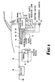
- an automobile is provided with a battery 10 which is connected to the starter motor 11 of an engine 12, without any interference of the wiring by the circuit of this invention.
- the positive rail 13 extends to a relay 14 of a protection circuit 15 as illustrated in Fig. 2, and the relay is connected through conductors 16, 17 and 18 to the protection circuit 15, the conductor 18 being in direct communication with the accessories of the motor vehicle, and a conductor 19 is coupled to an alarm output if such exists on the vehicle.
- the protection circuit 15 Within the cabin of the vehicle, desirably at the location of the dash panel, there is located the protection circuit 15, also a reset switch 31 and indicator lamp 28 in a small console 20, an ignition switch 21 and an accessory switch 22.
- the interconnection of those elements with the circuit 15 is shown in some detail in Fig. 2.
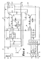
- Fig. 2 wherein there are two comparator circuits 24 and 25, the comparator circuit 24 being a voltage comparator and the comparator circuit 25 being an override circuit to override the battery cut-off circuit when it is required to restart the engine for example.
- Each circuit contains a respective portion of a dual comparator 26, the portions respectively being marked IC1a and IC1b.
- the voltage of battery 10 is divided by the resistors R9 and R10, and compared to a temperature compensated voltage reference with comprises a Zener diode ZD3, and the diodes D7, D8, D9 and D10 in circuit with the variable resistor R8.
- the cut-off point is preset by adjustment of the resistor R8.
- the comparator IC1 is supplied with power via R5 and ZD1, capacitor C1 being across the Zener diode ZD1, the Zener diode ZD1 and capacitor C1 functioning to remove any voltage transients.
- the battery should not be out of circuit if the ignition switch is turned on, which in turn provides energy for the accessories of the vehicle, or if the reset button has been pushed, or thirdly if an alarm system has been activated.
- the reset button 31, the alarm circuit 32 (if used on the vehicle) or the ignition switch 21 or the accessories switch 22 (incorporated in the ignition switch 21) will respectively include the diodes D1 and D2; D3, D4, D5 and D6, which provide low resistance current flow paths and inhibit interference between the inputs.
- the voltage is "clamped” by the Zener diode ZD2 and capacitor C2 to remove any voltage transients, and biased to ground by resistor R7.
- the output of the portion IC1b of the comparator 26 is high (greater than the voltage set by the voltage divider R7, R12) and the (NPN) transistor Q2 is turned on by the resistor R16, diode D12 and resistor R22, and in turn turns on the (PNP) transistor Q4 which applies full voltage to the relay 14.
- the portion IC1b of comparator 26 will go low and after a time delay due to interaction of capacitor C4 and resistor R18, the transistors Q2 and Q4 are turned off and the supply to the relay 14 is also turned off.
- a simple transistor circuit may be used in lieu of comparator IC1b.
- the circuit is a "fail safe" circuit, and if the circuit fails, the diodes D1 and D6 (reset button 31 and accessories switch 22 of the ignition switch 21) apply current directly to the relay coil of relay 14. Provided the relay has not failed, the vehicle can be started by turning the key to the accessories position and pushing the reset button and this will bring full power back to the vehicle.
- the R-C time delay of resistor R17 and capacitor C3 in the comparator circuit portion 24 is set so that sudden changes in battery voltage do not trigger the circuit to turn off. This also prevents entry to the vehicle (for example due to interior lights being illuminated) from triggering the circuit.
- the indicator LED28 will become illuminated whenever the voltage is low.
- the R-C time delay associated with resistor R18 and capacitor C4 is set so that once an override condition has occurred, the battery voltage has time to settle before being monitored. For example, if the vehicle has been idling with many loads on and the battery voltage is low (indicated by illumination of LED 28) and is then turned off with loads disconnected and the engine stopped, the battery voltage can slowly rise. There is therefore a need to have a delay in time.
- the comparator IC1b Since the alarm circuit 32 is connected through the diode D3 and resistor R2 to IC1b of comparator 26, the comparator IC1b will maintain the relay 27 energised for the alarm to sound and other accessories connected thereto (for example hazard lights or horn) will operate without the circuit disconnecting the battery. If the circuit has tripped and power is off and the alarm is energised, the circuit will override and reconnect the battery with the electrical system.
Landscapes
- Engineering & Computer Science (AREA)
- Power Engineering (AREA)
- Protection Of Static Devices (AREA)
Applications Claiming Priority (2)
| Application Number | Priority Date | Filing Date | Title |
|---|---|---|---|
| AU9622/90 | 1990-04-12 | ||
| AUPJ962290 | 1990-04-12 |
Publications (2)
| Publication Number | Publication Date |
|---|---|
| EP0452073A2 true EP0452073A2 (de) | 1991-10-16 |
| EP0452073A3 EP0452073A3 (en) | 1992-09-23 |
Family
ID=3774605
Family Applications (1)
| Application Number | Title | Priority Date | Filing Date |
|---|---|---|---|
| EP19910303087 Withdrawn EP0452073A3 (en) | 1990-04-12 | 1991-04-09 | Battery power cut-off circuit |
Country Status (2)
| Country | Link |
|---|---|
| US (1) | US5136230A (de) |
| EP (1) | EP0452073A3 (de) |
Cited By (3)
| Publication number | Priority date | Publication date | Assignee | Title |
|---|---|---|---|---|
| NL1000175C2 (nl) * | 1995-04-19 | 1996-10-22 | White Holding B V | Batterijklem. |
| GB2452491A (en) * | 2007-09-04 | 2009-03-11 | Martin Wilkinson | Vehicle battery voltage charge sensing and isolating device |
| EP3118965A1 (de) * | 2015-07-15 | 2017-01-18 | Hyundai Motor Company | Gerät zur verwaltung der stromversorgung einer batterie |
Families Citing this family (11)
| Publication number | Priority date | Publication date | Assignee | Title |
|---|---|---|---|---|
| US5325038A (en) * | 1991-06-10 | 1994-06-28 | Nippondenso Co., Ltd. | Driving apparatus for controlling an electric load in a vehicle |
| US5321389A (en) * | 1992-11-27 | 1994-06-14 | Echlin, Incorporated | Battery charge monitor |
| US5691619A (en) * | 1994-10-31 | 1997-11-25 | Vingsbo; Stefan G. | Automatic safety switch for preventing accidental battery discharge |
| US5693986A (en) * | 1995-06-12 | 1997-12-02 | Chrysler Corporation | Method and device for disconnecting loads from a motor vehicle body |
| US7671483B2 (en) * | 2006-02-06 | 2010-03-02 | Constant Leamon A | Remote isolator interface |
| US7898219B2 (en) * | 2008-02-25 | 2011-03-01 | Jimmie Doyle Felps | On-board battery supervisor |
| US9312678B2 (en) * | 2012-09-13 | 2016-04-12 | Cyber Power Systems Inc. | Surge protection device |
| US9008907B2 (en) | 2013-05-31 | 2015-04-14 | Hugh D Copeland | Intelligent vehicle power control system and method |
| US8958956B1 (en) | 2014-03-10 | 2015-02-17 | Jimmie Doyle Felps | Battery supervisor system having smart winch control |
| WO2017214657A1 (en) * | 2016-06-14 | 2017-12-21 | Lumen International Holdings Pty Ltd | Electrical systems and components and methods therefor |
| US11225167B2 (en) * | 2018-10-02 | 2022-01-18 | Assembled Products Corporation | Electric cart |
Family Cites Families (11)
| Publication number | Priority date | Publication date | Assignee | Title |
|---|---|---|---|---|
| US3721887A (en) * | 1971-11-24 | 1973-03-20 | American Telephone & Telegraph | Battery protection circuit |
| US4137557A (en) * | 1974-05-15 | 1979-01-30 | Societa Italiana Vetro S/V S.P.A. | Automatic cut-out device |
| SE7505410L (sv) * | 1974-05-15 | 1975-11-17 | Vetro Sic Spa Soc It | Automatisk anordning for bortkoppling av ovesentliga belastningar. |
| GB2010028B (en) * | 1977-11-04 | 1982-04-28 | Minitronics Pty Ltd | Control of power supply |
| US4218717A (en) * | 1978-08-21 | 1980-08-19 | Harry Shuster | Electric control system for motor vehicle |
| US4493001A (en) * | 1983-11-10 | 1985-01-08 | General Motors Corporation | Motor vehicle battery rundown protection system |
| US4902956A (en) * | 1986-12-12 | 1990-02-20 | Sloan Jeffrey M | Safety device to prevent excessive battery drain |
| WO1989012343A1 (en) * | 1988-06-06 | 1989-12-14 | Brett David Dornbusch | Accumulator switching/security apparatus |
| GB8818247D0 (en) * | 1988-08-01 | 1988-09-07 | Motronix Ltd | Protective circuit for battery powered engine ignition system |
| GB8821167D0 (en) * | 1988-09-09 | 1988-10-12 | Jaguar Cars | Electrical supply control system for motor vehicle |
| DE8815410U1 (de) * | 1988-12-12 | 1989-03-16 | Wemhöner, Jürgen, 8000 München | Schutzschalter zur Sicherstellung der Startenergie in Kraftfahrzeugen mit Verbrennungsmotoren |
-
1991
- 1991-04-09 EP EP19910303087 patent/EP0452073A3/en not_active Withdrawn
- 1991-04-11 US US07/683,975 patent/US5136230A/en not_active Expired - Fee Related
Cited By (4)
| Publication number | Priority date | Publication date | Assignee | Title |
|---|---|---|---|---|
| NL1000175C2 (nl) * | 1995-04-19 | 1996-10-22 | White Holding B V | Batterijklem. |
| WO1996033078A1 (en) * | 1995-04-19 | 1996-10-24 | Power-Motive B.V. | Battery clamp |
| GB2452491A (en) * | 2007-09-04 | 2009-03-11 | Martin Wilkinson | Vehicle battery voltage charge sensing and isolating device |
| EP3118965A1 (de) * | 2015-07-15 | 2017-01-18 | Hyundai Motor Company | Gerät zur verwaltung der stromversorgung einer batterie |
Also Published As
| Publication number | Publication date |
|---|---|
| US5136230A (en) | 1992-08-04 |
| EP0452073A3 (en) | 1992-09-23 |
Similar Documents
| Publication | Publication Date | Title |
|---|---|---|
| US5136230A (en) | Battery power cut-off circuit | |
| US5691619A (en) | Automatic safety switch for preventing accidental battery discharge | |
| EP0433328B1 (de) | Elektrische stromversorgungseinrichtung für kraftfahrzeuge | |
| US6249106B1 (en) | Apparatus and method for maintaining a threshold value in a battery | |
| US5170151A (en) | Method and assembly for disconnecting a battery from its operating system | |
| US3474296A (en) | Low voltage cut-out device | |
| US5404129A (en) | Anti-theft battery system for vehicles | |
| US5764469A (en) | Apparatus for protecting eletronic devices in a vehicle's electronic system and for preventing discharge of the vehicle's battery | |
| US5453730A (en) | Auto anti-theft system | |
| US4149093A (en) | Battery protection device | |
| WO1990006614A1 (en) | Safety device to prevent excessive battery drain | |
| US4992670A (en) | Ignition disabling anti-theft device | |
| US3764879A (en) | Battery charging systems for road vehicles | |
| US4300495A (en) | Car theft preventer | |
| US4278963A (en) | Automotive anti-theft system | |
| US2935730A (en) | Vehicle alarm system | |
| US4672225A (en) | Automotive anti-theft device | |
| US4262279A (en) | Alarm system for use in a vehicle and method | |
| AU649659B2 (en) | Battery power cut-off circuit | |
| US4878042A (en) | Apparatus for flashing vehicle lights to warn of engine stall | |
| US7166990B2 (en) | Battery low-voltage protecting device | |
| US20110196566A1 (en) | "Night Ops" vehicle blackout safety system | |
| US4371052A (en) | Anti-theft device for motor vehicles | |
| US5529142A (en) | Vehicle theft prevention device | |
| EP0632558B1 (de) | Schutzeinrichtung mit automatischer Rückstellung gegen Kurzschlüsse in elektrischen Systemen an Bord von Kraftfahrzeugen |
Legal Events
| Date | Code | Title | Description |
|---|---|---|---|
| PUAI | Public reference made under article 153(3) epc to a published international application that has entered the european phase |
Free format text: ORIGINAL CODE: 0009012 |
|
| AK | Designated contracting states |
Kind code of ref document: A2 Designated state(s): DE FR GB |
|
| PUAL | Search report despatched |
Free format text: ORIGINAL CODE: 0009013 |
|
| AK | Designated contracting states |
Kind code of ref document: A3 Designated state(s): DE FR GB |
|
| 17P | Request for examination filed |
Effective date: 19930315 |
|
| 17Q | First examination report despatched |
Effective date: 19940526 |
|
| STAA | Information on the status of an ep patent application or granted ep patent |
Free format text: STATUS: THE APPLICATION IS DEEMED TO BE WITHDRAWN |
|
| 18D | Application deemed to be withdrawn |
Effective date: 19941206 |