EP0452126A2 - Vorrichtung zum Orientieren eines Perforators - Google Patents
Vorrichtung zum Orientieren eines Perforators Download PDFInfo
- Publication number
- EP0452126A2 EP0452126A2 EP91303209A EP91303209A EP0452126A2 EP 0452126 A2 EP0452126 A2 EP 0452126A2 EP 91303209 A EP91303209 A EP 91303209A EP 91303209 A EP91303209 A EP 91303209A EP 0452126 A2 EP0452126 A2 EP 0452126A2
- Authority
- EP
- European Patent Office
- Prior art keywords
- tool
- tool body
- gun
- sleeve
- perforating gun
- Prior art date
- Legal status (The legal status is an assumption and is not a legal conclusion. Google has not performed a legal analysis and makes no representation as to the accuracy of the status listed.)
- Granted
Links
Images



Classifications
-
- E—FIXED CONSTRUCTIONS
- E21—EARTH OR ROCK DRILLING; MINING
- E21B—EARTH OR ROCK DRILLING; OBTAINING OIL, GAS, WATER, SOLUBLE OR MELTABLE MATERIALS OR A SLURRY OF MINERALS FROM WELLS
- E21B43/00—Methods or apparatus for obtaining oil, gas, water, soluble or meltable materials or a slurry of minerals from wells
- E21B43/11—Perforators; Permeators
- E21B43/116—Gun or shaped-charge perforators
-
- E—FIXED CONSTRUCTIONS
- E21—EARTH OR ROCK DRILLING; MINING
- E21B—EARTH OR ROCK DRILLING; OBTAINING OIL, GAS, WATER, SOLUBLE OR MELTABLE MATERIALS OR A SLURRY OF MINERALS FROM WELLS
- E21B17/00—Drilling rods or pipes; Flexible drill strings; Kellies; Drill collars; Sucker rods; Cables; Casings; Tubings
- E21B17/10—Wear protectors; Centralising devices, e.g. stabilisers
- E21B17/1057—Centralising devices with rollers or with a relatively rotating sleeve
-
- E—FIXED CONSTRUCTIONS
- E21—EARTH OR ROCK DRILLING; MINING
- E21B—EARTH OR ROCK DRILLING; OBTAINING OIL, GAS, WATER, SOLUBLE OR MELTABLE MATERIALS OR A SLURRY OF MINERALS FROM WELLS
- E21B17/00—Drilling rods or pipes; Flexible drill strings; Kellies; Drill collars; Sucker rods; Cables; Casings; Tubings
- E21B17/10—Wear protectors; Centralising devices, e.g. stabilisers
- E21B17/1057—Centralising devices with rollers or with a relatively rotating sleeve
- E21B17/1064—Pipes or rods with a relatively rotating sleeve
-
- E—FIXED CONSTRUCTIONS
- E21—EARTH OR ROCK DRILLING; MINING
- E21B—EARTH OR ROCK DRILLING; OBTAINING OIL, GAS, WATER, SOLUBLE OR MELTABLE MATERIALS OR A SLURRY OF MINERALS FROM WELLS
- E21B23/00—Apparatus for displacing, setting, locking, releasing or removing tools, packers or the like in boreholes or wells
-
- E—FIXED CONSTRUCTIONS
- E21—EARTH OR ROCK DRILLING; MINING
- E21B—EARTH OR ROCK DRILLING; OBTAINING OIL, GAS, WATER, SOLUBLE OR MELTABLE MATERIALS OR A SLURRY OF MINERALS FROM WELLS
- E21B43/00—Methods or apparatus for obtaining oil, gas, water, soluble or meltable materials or a slurry of minerals from wells
- E21B43/11—Perforators; Permeators
- E21B43/119—Details, e.g. for locating perforating place or direction
-
- E—FIXED CONSTRUCTIONS
- E21—EARTH OR ROCK DRILLING; MINING
- E21B—EARTH OR ROCK DRILLING; OBTAINING OIL, GAS, WATER, SOLUBLE OR MELTABLE MATERIALS OR A SLURRY OF MINERALS FROM WELLS
- E21B47/00—Survey of boreholes or wells
- E21B47/02—Determining slope or direction
- E21B47/024—Determining slope or direction of devices in the borehole
Definitions
- This invention relates to well perforating and in particular to the orientation of a perforating gun in a deviated well to line up with the formation to be perforated.
- the platform may support the well head equipment for numerous wells, perhaps as many as sixty-four. Needless to say, while all sixty-four wells may come together at the platform, they terminate at multiple locations across the formation of interest. This involves the drilling of deviated wells from the platform. Several such wells are drilled in which a substantial portion of each well is inclined from the vertical. It is not uncommon to have an inclination of as much as fifty, and even up to about seventy degrees deviation from the vertical.
- the positioning of tools such as perforating guns in deviated wells presents a number of problems. Not only does the well deviation itself give rise to certain difficulties, but in addition the formation to be perforated may well not itself be truly horizontal.
- the formations can slope upwardly or downwardly with respect to a horizontal reference plane. They might be as much as forty, fifty or even sixty degrees inclined from the horizontal reference.
- formations have a type of grain which extends through them. This is sometimes known as the formation bedding plane or the fracture plane. These are planes which are found within the formation and which define a preference (which may very strong) for production fluid flow.
- an apparatus for orienting a perforating gun in a deviated well borehole which apparatus comprises an elongate tool body having upper and lower ends and defining an axis of rotation; at least two spaced apart, circumferential cylindrical sleeves encircling said tool body and having bearing means to enable said tool body to rotate internally relative to said sleeves; weight means positioned between said sleeves and located eccentrically relative to the axis of rotation; an elongated perforating gun carrier sleeve for supporting a plurality of shaped charges, said carrier sleeve being positioned between said circumferential cylindrical sleeves and releasably connected to said weight means for rotational movement therewith; and means for releasably locking said elongated perforating gun carrier sleeve to said weight means such that shaped charges supported by said perforating gun carrier sleeve can be locked at a predetermined angular position relative to the eccentrically located weight of the weight means.
- the invention also includes a method of positioning a perforating gun in a deviated well borehole oriented adjacent a formation of interest wherein, in an apparatus of the invention, the gun carrier sleeve is locked at a predetermined angular position relative to the weight means, and the apparatus is then lowered on a wireline into the wellbore to a depth at which the gun sleeve is adjacent the formation of interest.
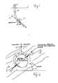
- a deviated well 10 extends from a drilling rig 11 which is at the surface, either on land or at sea.
- the deviated well 10 extends at some angle, i.e. it deviates from the vertical.
- a vertical reference direction is indicated by the arrow 12.
- the direction of the well in that region is indicated by the arrow 13.
- the angle between the lines 12 and 13 is the angle of deviation. It can be as much as seventy degrees or so.
- the well is cased and the casing is cemented in place. Locations along the cased well can be determined by utilizing a casing collar locator (CCL) so that a formation of interest can be located.
- CCL casing collar locator
- the formation 14 extends at an angle 15 with respect to the horizontal reference line shown in Fig. 2 of the drawings.
- the vertical reference 12 again is reproduced in Fig. 2.
- the vertical reference 12 defines the horizon which serves as a reference.
- the formation 14 includes formation bedding planes 16 which extend with the formation. These define what is, loosely speaking, formation grain.
- the formation grain makes it highly desirable that perforations are formed parallel to the bedding plane 16. It is generally desirable that the perforations formed be precisely parallel. Obviously, this type of precision is not essential but it is highly desirable that the perforations extend approximately or close to the bedding plane angle.
- the perforations 17 shown in Fig. 2 are almost parallel to the formation bedding plane.
- Fig. 2 is taken through the formation and only two perforations are shown, one extending up in the formation and the other extending downwardly in the formation. It is desirable that multiple formations be formed parallel to the perforations 17 shown in Fig. 2. They will all collectively be parallel to each other and hence or ideally parallel to the bedding plane 16 of the formation 14.
- the present procedure is normally a completion procedure. That is, the well has been drilled and it has been determined that there is sufficient interest in production that the well should be csed and the casing cemented in place. Moreover, it is normally known in advance what particular formation is the production zone, and information about that zone is obtained. This information includes the angle 15 which describes the angle of the formation bedding plane with respect to the horizontal reference, see Fig. 2. In other words, the angle 15 is known at this juncture. Typically, a survey of the well 10 is also run and this provides a map or chart of the path of the well. Thus, the slant or deviation angle of the well is also known in advance. It is generally known that the zone has a specified thickness also.
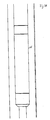
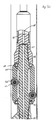
- a tool of the present invention is then used to form the perforations which will be described. Going now to Fig. 3 of the drawings, one embodiment of tool of the present invention is shown in a cased well. The description will proceed from top to bottom. Fig. 3 is formed of several sequential sections which are illustrated in sequence to provide a full description of the apparatus.
- the tool is indicated generally by the numeral 20. It incorporates a cable head assembly for attachment to the wireline at 21. It is typically run in the well by connection with a wireline which connects at the cable head and suitable electrical connections are also included. These communicate through the wireline and connect to various components of the tool as will be described.
- the top end of the tool incorporates a swivel 22, typically a purchased item, which in the preferred embodiment is a pressure balanced wireline swivel which cancels torque from the wireline as it is reeled from the storage drum and extended in the well 10.
- the tool supports a navigation package 23 preferably containing a gravity operated pendulum connecting with a potentiometer which provides a signal for the surface.
- the signal indicates the angle of perforating shot plane of the tool with respect to the vertical.
- the tool also includes a casing collar locator (CCL) 24.
- CCL casing collar locator
- An axial passage 25 provides an electrical pathway for conductors which extend through the tool from the very top to the bottom.
- One conductor extends to the bottom of the perforating assembly 20 to operate a detonator mechanism.
- Passage 25 extends through a sub 26, and the sub has an axial bore therethrough as mentioned which is countersunk to receive a mandrel 27.
- the mandrel 27 continues therebelow.
- the mandrel 27 is surrounded by a skirt 28 at the upper end, the skirt being appended to the sub 26 and formed integrally therewith.
- These two members are preferably threaded together and are joined when the tool is assembled.
- the skirt 28, however, terminates at the lower end and supports an abutting bearing assembly 29.
- the bearing assembly in turn supports a spaced sleeve 30.
- the sleeve 30 is supported by a similar bearing assembly 31 at its lower end. Both bearing assemblies are locked in place. They permit the sleeve 30 to rotate freely.
- the sleeve supports one or more rollers 32 for freewheeling motion on an axle 33. There is a window cut in the sleeve to enable the roller to extend outwardly.
- the rollers are duplicated. For instance, two sets of three or four rollers typically will suffice.
- the sleeve is able to rotate in either direction and thereby functions as a type of cradle assembly for the tool.
- rollers contact the surrounding casing that makes up the well borehole. It is not essential that the rollers contact at all points around the circle which confines the tool within the casing. Rather, the maximum diameter of the tool measured at the rollers is something less so that the tool is able to traverse locations where the casing is not perfectly circular. Moreover, the rollers 32 are sized so that they contact on what might be termed the bottom side of the tool.
- Fig. 3 shows the tool in a vertical position as when it is first placed in the well. When the tool reaches a deviated part of the well, however, one roller (eg.
- the mandrel 27 threads into an eccentric sub 35.
- This has an offset enlargement 36 which is eccentrically mounted.
- the eccentric weight 36 extends along the length of the sub. It hangs to the low side when permitted to rotate.
- the sub 35 rotates with the mandrel 27.
- the mass of the eccentric 36 is sufficient to cause rotation.
- rotation of the mandrel 27 occurs, it rotates within the sleeve 30 which is connected to it by the upper and lower bearing assemblies previously described.
- the eccentric 36 thus hangs to the lower side.
- the eccentric 36 is axially drilled with the passage 37 which terminates at a larger chamber 38 to enable wiring communication through the tool.
- the eccentric is a portion of the sub 35 and it is shaped with a circular external surface.
- a shoulder 39 limits upward movement of a hollow lock nut 40.
- the lock nut 40 is threaded for locking purposes. This is described below.
- the lock nut 40 has a lower peripheral edge 41 which abuts a lock ring 42.
- the ring 42 is received in an encircling groove 43 around the sub 35.
- the sub 35 also abuts a shoulder 44 which is formed in an adjacent sub 45.
- the sub 45 has an upstanding internally threaded skirt 46.
- the lock nut 40 threads to the sub 45 at the threads on the skirt 46.
- the lock nut 40 is threaded to move upwardly, it disengages the lock ring 42.
- the nut 40 is rotated in the opposite direction and is forced downwardly, it jams the lock ring 42 and forces the ring against the eccentric sub 35 so that the eccentric sub 35 is jammed against the sub 45 and held in fixed relationship on the shoulder 44.
- the subs 35 and 45 are thus locked together by the nut 40 when it is rotated to the down or locked position and they are free to relatively rotate when the lock nut 40 is in the up position.
- the lock nut 40 is controllably installed to selectively fasten the subs 35 and 45 together so that they are prevented from relative rotation. Rotation is desirable so that the sub 45 can be rotated to a particular angle with respect to the eccentric 36. The purpose of this will be more apparent on description of the tool at the time of installing the shaped charges.
- the sub 45 is threaded to an elongate perforating gun assembly 47.
- the gun 47 has an enclosure formed of an elongate sleeve which is an axially hollow sleeve which encloses one or more shaped charges pointing radially outwardly.
- the sleeve is provided with thin wall scallops 48 aligned with the shaped charges forming perforations at the circular scallops.
- the several shaped charges are supported by a common assembly aligned in the sleeve enclosure 47. This keeps all the debris after firing collected in the enclosing hollow sleeve 47.
- rows of shaped charges are installed and they are aligned to fire in the same radial direction.
- the sleeve has interior space to support the multiple shaped charges.
- the passage 37 extends the connection pathway through the tool.
- the shaped charges are connected with a detonator mechanism located at the bottom of the perforating gun tool.
- the external sleeve being axially hollow, is able to receive and support the necessary connections for rows of shaped charges.
- the preferred embodiment preferably includes two sets of shaped charges, the sets being positioned to form two opposing sets of perforations.
- the housing connects with another sub 50 and is threaded to it in the same fashion as the sub 45 thereabove.
- the lock nut 40 is duplicated by the lock nut 55. This engages a similar ring 51 which causes the sub 50 to thread to and lock with a second eccentric sub 56.
- the passage 37 in the upper portion of the drawing is also extended at 52 through the sub 50 and again is extended at 53 through the eccentric sub 56. Since the lock nut 55 operates in the same fashion as the lock nut 40, it is believed that the foregoing description can likewise be applied to this lock nut so that it will be understood how the eccentric sub 56 is controllably locked to the elongate sleeve supporting the several shaped charges.
- the eccentric sub 56 is drilled with an offset passage and supports a mandrel 58 which is similar in construction and purpose to the mandrel 27 previously mentioned.
- the mandrel 58 is threaded to the sub 56 thereabove.
- a bearing assembly 59 is shown therebelow and supports a surrounding sleeve 60 which is identical to the sleeve 30. It extends downwardly to another bearing assembly 61. In turn, this supports plural rollers 62 which are mounted on the appropriate axles 63. This enables a duplicate set of rollers to that shown at the top end of the tool to be positioned by the sleeve 60 for rotation.
- the sleeve is able to rotate, thereby providing a mechanism whereby the sleeve operates as a cradle which permits the equipment passing through the center thereof to rotate.
- the upper sleeve 30 and the lower sleeve 60 are similar in construction and operation.
- the lower end of the mandrel 58 is threaded to an enclosed sub 65 having a chamber 66 for enclosing the detonation equipment.
- the mandrel 58 thereabove is provided with the axial passage 64 which extends through it and connects with the chamber 66.
- a conductor for firing is extended along the several passages shown in Fig. 3 and is received in the chamber 66 where it connects with the detonation equipment. In turn, the passage also received the conductors extending from the detonator back to the charges for operation of the charges.
- the lock nut 55 is likewise fastened.
- the eccentric weights 36 and 56 hang to the side at a common azimuth with respect to the shaped charges supported by the sleeve 47.
- the sleeve 47 and enclosed shaped charges are mounted eccentrically.
- the sleeve can be as short or long as needed; it is not uncommon for the sleeve to be twenty feet (6.1 m) long. In a longer length, the greater portion of tool weight is eccentered. For instance, in a 500 pound (227 kg) tool (with guns), as much as seventy-five or eighty percent of the weight is eccentric.
- the navigation package is turned on and its relative position to the eccentric weight is recorded.
- the tool is then lowered into the well borehole.
- the CCL counts the casing collars as the tool travels downwardly.
- the tool travels rather smoothly because it is equipped with rollers, upper and lower rollers in particular, which enable it to travel smoothly.
- the depth of the tool in the well is determined.
- the navigation equipment forms an output signal which is indicative of the shaped charges phase orientation with respect to the vertical. Referring to Fig. 2, this equipment measures the angle of the perforating gun assembly with respect to the vertical reference 12.
- Tool rotation involves the rotor carriages at the upper and lower ends of the tool.
- the rollers on the two sleeves contact the casing which defines the well borehole, and permit the tool to rotate along its lengthwise axis.
- This rotation is driven by the eccentrics which extend to a common azimuth.
- the eccentrics are pointed in a particular direction when the tool is first placed in the well borehole. At the surface, however, the tool is vertical and the eccentrics are not free to fall to the gravity side or down side.
- the eccentrics fall to the low side of the well. This causes rotation of the entire tool. Rotation is not resisted by the cable which is connected to the tool because the tool includes the swivel mechanism 22 at the upper end and that permits the tool to rotate in either direction without bias and further permits it to rotate sufficiently that the eccentrics fall to the down or bottom side.
- the two eccentrics and perforating gun 47 thus move to the down side and define the vertical line 12 shown in Fig. 2. When that occurs, the shaped charges within the sleeve are then correctly positioned.
- the sleeve was rotated with respect to the eccentrics, it is thus now positioned so that the perforations 17 shown in Fig. 2 are formed as close as possible parallel to the formation bedding plane. This enables the perforations to have greater length and to extend deeper into the formation of interest, and to provide the resultant production.
- the tool can then be fired.
- the sequence therefore has the first step of determining that the tool is at the right well depth, then measuring the angle of orientation of the tool which measurement is compared by means of the navigation package with the anticipated orientation. If a match is obtained, this indicates the tool is at the right well depth and orientation with respect to the vertical reference.
- Time is permitted for the tool to rotate inside the roller mounted cradles at the upper and lower ends of the tool. If desired, while monitoring the navigation package data and recording at the surface the tool can be raised and lowered gently a few times, moving only a few feet on each stroke, all for the purpose of permitting rotation. Rotation is accomplished so that the perforating guns are then correctly referenced to the vertical lines in Figs. 1 and 2. This then positions the perforating guns for operation.
- a signal from the surface is transmitted down the wireline. It travels through conductors in the several passages through the tool to the chamber 66 at the lower end.
- the detonation equipment is located in that chamber, and in turn, that forms a signal producing detonation.
- That signal is conveyed to the various perforating charges and they are fired by that signal.
- the tool After firing, the tool is retrieved on the wireline. It travels easily out of the well borehole because it is travelling in the slant well supported on rollers. When it is in the vertical part of the well, contact with the casing is somewhat incidental. It can be retrieved quickly and at the surface, the sleeve and spent shaped charges in the sleeve is discarded and a gun assembly 47 is installed. If needed, the relative angle of the shaped charge (when fired) is adjusted by adjustment of the angular position of the threaded skirt 46 with respect to the eccentrics. In summary, the device can be readjusted so that each use of the device can move to a different angular direction.
Landscapes
- Engineering & Computer Science (AREA)
- Geology (AREA)
- Life Sciences & Earth Sciences (AREA)
- Mining & Mineral Resources (AREA)
- Physics & Mathematics (AREA)
- Environmental & Geological Engineering (AREA)
- Fluid Mechanics (AREA)
- General Life Sciences & Earth Sciences (AREA)
- Geochemistry & Mineralogy (AREA)
- Mechanical Engineering (AREA)
- Geophysics (AREA)
- Geophysics And Detection Of Objects (AREA)
- Earth Drilling (AREA)
Applications Claiming Priority (2)
| Application Number | Priority Date | Filing Date | Title |
|---|---|---|---|
| US508749 | 1990-04-12 | ||
| US07/508,749 US5040619A (en) | 1990-04-12 | 1990-04-12 | Wireline supported perforating gun enabling oriented perforations |
Publications (3)
| Publication Number | Publication Date |
|---|---|
| EP0452126A2 true EP0452126A2 (de) | 1991-10-16 |
| EP0452126A3 EP0452126A3 (en) | 1992-12-16 |
| EP0452126B1 EP0452126B1 (de) | 1995-10-11 |
Family
ID=24023920
Family Applications (1)
| Application Number | Title | Priority Date | Filing Date |
|---|---|---|---|
| EP91303209A Expired - Lifetime EP0452126B1 (de) | 1990-04-12 | 1991-04-11 | Vorrichtung zum Orientieren eines Perforators |
Country Status (4)
| Country | Link |
|---|---|
| US (1) | US5040619A (de) |
| EP (1) | EP0452126B1 (de) |
| CA (1) | CA2040281C (de) |
| DE (1) | DE69113672D1 (de) |
Cited By (15)
| Publication number | Priority date | Publication date | Assignee | Title |
|---|---|---|---|---|
| WO1999053172A1 (en) * | 1998-04-16 | 1999-10-21 | Schlumberger Technology Corporation | Orienting downhole tools |
| US6173773B1 (en) | 1999-04-15 | 2001-01-16 | Schlumberger Technology Corporation | Orienting downhole tools |
| GB2374887A (en) * | 2001-04-27 | 2002-10-30 | Schlumberger Holdings | Orienting perforating guns and confirming their orientation upon firing |
| GB2390623A (en) * | 2001-04-27 | 2004-01-14 | Schlumberger Holdings | Orienting perforating guns by eccentric weighting |
| GB2401383A (en) * | 2003-05-09 | 2004-11-10 | Schlumberger Holdings | Method and apparatus for orienting perforating devices |
| EP1308599A3 (de) * | 1999-07-12 | 2005-04-06 | Halliburton Energy Services, Inc. | Rotationsbremse für Richtbohrvorrichtung |
| GB2412132A (en) * | 2002-12-19 | 2005-09-21 | Schlumberger Holdings | Optimising charge phasing of a perforating gun |
| US7188689B2 (en) | 2003-11-07 | 2007-03-13 | Halliburton Energy Services, Inc. | Variable gauge drilling apparatus and method of assembly therefor |
| US7306058B2 (en) | 1998-01-21 | 2007-12-11 | Halliburton Energy Services, Inc. | Anti-rotation device for a steerable rotary drilling device |
| US8066059B2 (en) * | 2005-03-12 | 2011-11-29 | Thru Tubing Solutions, Inc. | Methods and devices for one trip plugging and perforating of oil and gas wells |
| US8448700B2 (en) | 2010-08-03 | 2013-05-28 | Thru Tubing Solutions, Inc. | Abrasive perforator with fluid bypass |
| US9228422B2 (en) | 2012-01-30 | 2016-01-05 | Thru Tubing Solutions, Inc. | Limited depth abrasive jet cutter |
| US9903185B2 (en) | 2014-02-12 | 2018-02-27 | Owen Oil Tools Lp | Perforating gun with eccentric rotatable charge tube |
| US10677024B2 (en) | 2017-03-01 | 2020-06-09 | Thru Tubing Solutions, Inc. | Abrasive perforator with fluid bypass |
| US11414965B2 (en) | 2018-02-27 | 2022-08-16 | Schlumberger Technology Corporation | Rotating loading tube and angled shaped charges for oriented perforating |
Families Citing this family (45)
| Publication number | Priority date | Publication date | Assignee | Title |
|---|---|---|---|---|
| US5076355A (en) * | 1990-12-21 | 1991-12-31 | Baker Hughes Incorporated | Perforating gun with auger |
| US5273121A (en) * | 1992-04-03 | 1993-12-28 | Eastern Oil Tools Pte Ltd. | Intercarrier mechanism for connecting and orienting tubing conveyed perforating guns |
| AU6412494A (en) * | 1993-04-07 | 1994-10-24 | Marathon Oil Company | High angle and horizontal wellbore centralizer and method of use |
| CA2120283C (en) * | 1994-03-30 | 2004-05-18 | Bernard Heinrichs | Down-hole gas separator |
| CA2122163C (en) * | 1994-04-26 | 1999-04-27 | Jim Edward Best | Method and apparatus for erosive stimulation of open hole formations |
| FR2722238B1 (fr) * | 1994-07-05 | 1996-08-30 | Inst Francais Du Petrole | Ensemble de mesure comportant des moyens d'orientation d'une partie des elements de mesure |
| US6868906B1 (en) | 1994-10-14 | 2005-03-22 | Weatherford/Lamb, Inc. | Closed-loop conveyance systems for well servicing |
| US7036610B1 (en) | 1994-10-14 | 2006-05-02 | Weatherford / Lamb, Inc. | Apparatus and method for completing oil and gas wells |
| GB9612524D0 (en) * | 1996-06-14 | 1996-08-14 | Anderson Charles A | Drilling apparatus |
| US5964294A (en) * | 1996-12-04 | 1999-10-12 | Schlumberger Technology Corporation | Apparatus and method for orienting a downhole tool in a horizontal or deviated well |
| GB9725740D0 (en) * | 1997-03-24 | 1998-02-04 | Sibille Patrick Neil | Apparatus and a method for use downhole |
| US6273189B1 (en) | 1999-02-05 | 2001-08-14 | Halliburton Energy Services, Inc. | Downhole tractor |
| DE60024129T2 (de) * | 1999-12-03 | 2006-07-20 | Wireline Engineering Ltd., Dyce | Bohrlochwerkzeug |
| GB2361723B (en) * | 2000-04-26 | 2002-11-13 | Schlumberger Holdings | Method of optimising perforation orientation to reduce sand production |
| US6656830B1 (en) | 2001-02-07 | 2003-12-02 | Advanced Micro Devices, Inc. | Dual damascene with silicon carbide middle etch stop layer/ARC |
| US6679327B2 (en) | 2001-11-30 | 2004-01-20 | Baker Hughes, Inc. | Internal oriented perforating system and method |
| US6679323B2 (en) | 2001-11-30 | 2004-01-20 | Baker Hughes, Inc. | Severe dog leg swivel for tubing conveyed perforating |
| US8365814B2 (en) * | 2007-09-20 | 2013-02-05 | Baker Hughes Incorporated | Pre-verification of perforation alignment |
| US8127848B2 (en) * | 2008-03-26 | 2012-03-06 | Baker Hughes Incorporated | Selectively angled perforating |
| US7878242B2 (en) * | 2008-06-04 | 2011-02-01 | Weatherford/Lamb, Inc. | Interface for deploying wireline tools with non-electric string |
| US7934558B2 (en) * | 2009-03-13 | 2011-05-03 | Halliburton Energy Services, Inc. | System and method for dynamically adjusting the center of gravity of a perforating apparatus |
| US8443886B2 (en) | 2010-08-12 | 2013-05-21 | CCS Leasing and Rental, LLC | Perforating gun with rotatable charge tube |
| US9200487B2 (en) * | 2010-12-13 | 2015-12-01 | Baker Hughes Incorporated | Alignment of downhole strings |
| US9500031B2 (en) | 2012-11-12 | 2016-11-22 | Aps Technology, Inc. | Rotary steerable drilling apparatus |
| US9702680B2 (en) | 2013-07-18 | 2017-07-11 | Dynaenergetics Gmbh & Co. Kg | Perforation gun components and system |
| EP3025012B1 (de) * | 2013-07-24 | 2017-11-01 | Impact Selector International, LLC | Kabelgeführter roller-standoff |
| CN106869823B (zh) * | 2017-03-07 | 2019-10-15 | 中国海洋石油集团有限公司 | 立管扶正系统及立管扶正装置 |
| CN108625780B (zh) * | 2017-03-23 | 2024-02-23 | 中石化石油工程技术服务有限公司 | 一种适于径向钻孔的偏心定位装置 |
| US11053782B2 (en) | 2018-04-06 | 2021-07-06 | DynaEnergetics Europe GmbH | Perforating gun system and method of use |
| US10458213B1 (en) | 2018-07-17 | 2019-10-29 | Dynaenergetics Gmbh & Co. Kg | Positioning device for shaped charges in a perforating gun module |
| CA3110488A1 (en) * | 2018-08-29 | 2020-03-05 | Impact Selector International, Llc | Apparatus and method for running casing into a wellbore |
| US11326410B2 (en) | 2019-03-14 | 2022-05-10 | Frac Innovation Llc | Orienting sub for well instruments |
| WO2020249744A2 (en) | 2019-06-14 | 2020-12-17 | DynaEnergetics Europe GmbH | Perforating gun assembly with rotating shaped charge holder |
| WO2021122797A1 (en) | 2019-12-17 | 2021-06-24 | DynaEnergetics Europe GmbH | Modular perforating gun system |
| US11499401B2 (en) | 2021-02-04 | 2022-11-15 | DynaEnergetics Europe GmbH | Perforating gun assembly with performance optimized shaped charge load |
| WO2022167297A1 (en) | 2021-02-04 | 2022-08-11 | DynaEnergetics Europe GmbH | Perforating gun assembly with performance optimized shaped charge load |
| US12366142B2 (en) | 2021-03-03 | 2025-07-22 | DynaEnergetics Europe GmbH | Modular perforating gun system |
| US11732556B2 (en) | 2021-03-03 | 2023-08-22 | DynaEnergetics Europe GmbH | Orienting perforation gun assembly |
| US12584363B2 (en) | 2021-04-22 | 2026-03-24 | GR Energy Services, Management, LP | Orientable weight bar for a downhole tool and method of using same |
| NO347757B1 (en) * | 2021-09-15 | 2024-03-18 | Well Conveyor As | A well tool with an angle orienting feature |
| US12253339B2 (en) | 2021-10-25 | 2025-03-18 | DynaEnergetics Europe GmbH | Adapter and shaped charge apparatus for optimized perforation jet |
| US20250027372A1 (en) * | 2021-12-03 | 2025-01-23 | Petromac Ip Limited | A tool string transportation device |
| MX2023008154A (es) | 2022-01-09 | 2023-07-21 | Gr Energy Services Man L P | Sistema de monitoreo de pozo con un rastreador de pozos y metodo de uso del mismo. |
| US11970914B1 (en) * | 2023-06-06 | 2024-04-30 | Petromac Ip Limited | Tool string transportation device |
| US12540542B2 (en) | 2024-07-11 | 2026-02-03 | Saudi Arabian Oil Company | Controlling logging tool orientation in a wellbore |
Family Cites Families (9)
| Publication number | Priority date | Publication date | Assignee | Title |
|---|---|---|---|---|
| US1721004A (en) * | 1928-04-23 | 1929-07-16 | Albert S Debose | Rotary well-drilling apparatus |
| US3209828A (en) * | 1962-11-01 | 1965-10-05 | Schlumberger Well Surv Corp | Perforating apparatus |
| US4068863A (en) * | 1976-10-14 | 1978-01-17 | Lasko John A | Pipe joint |
| US4194577A (en) * | 1977-10-17 | 1980-03-25 | Peabody Vann | Method and apparatus for completing a slanted wellbore |
| US4372622A (en) * | 1980-11-17 | 1983-02-08 | Cheek Alton E | Recirculating bearing antifriction system for well strings |
| US4410051A (en) * | 1981-02-27 | 1983-10-18 | Dresser Industries, Inc. | System and apparatus for orienting a well casing perforating gun |
| US4438810A (en) * | 1981-10-26 | 1984-03-27 | Dresser Industries, Inc. | Apparatus for decentralizing and orienting a well logging or perforating instrument |
| GB2128719B (en) * | 1982-10-20 | 1986-11-26 | Vann Inc Geo | Gravity oriented perforating gun for use in slanted boreholes |
| US4830120A (en) * | 1988-06-06 | 1989-05-16 | Baker Hughes Incorporated | Methods and apparatus for perforating a deviated casing in a subterranean well |
-
1990
- 1990-04-12 US US07/508,749 patent/US5040619A/en not_active Expired - Lifetime
-
1991
- 1991-04-11 EP EP91303209A patent/EP0452126B1/de not_active Expired - Lifetime
- 1991-04-11 DE DE69113672T patent/DE69113672D1/de not_active Expired - Lifetime
- 1991-04-11 CA CA002040281A patent/CA2040281C/en not_active Expired - Lifetime
Cited By (26)
| Publication number | Priority date | Publication date | Assignee | Title |
|---|---|---|---|---|
| US7306058B2 (en) | 1998-01-21 | 2007-12-11 | Halliburton Energy Services, Inc. | Anti-rotation device for a steerable rotary drilling device |
| WO1999053172A1 (en) * | 1998-04-16 | 1999-10-21 | Schlumberger Technology Corporation | Orienting downhole tools |
| GB2362403A (en) * | 1998-04-16 | 2001-11-21 | Camco Int | Orienting downhole tools |
| GB2362403B (en) * | 1998-04-16 | 2002-12-11 | Schlumberger Technology Corp | Orienting downhole tools |
| US6173773B1 (en) | 1999-04-15 | 2001-01-16 | Schlumberger Technology Corporation | Orienting downhole tools |
| EP1308599A3 (de) * | 1999-07-12 | 2005-04-06 | Halliburton Energy Services, Inc. | Rotationsbremse für Richtbohrvorrichtung |
| GB2374887A (en) * | 2001-04-27 | 2002-10-30 | Schlumberger Holdings | Orienting perforating guns and confirming their orientation upon firing |
| GB2374887B (en) * | 2001-04-27 | 2003-12-17 | Schlumberger Holdings | Method and apparatus for orienting perforating devices |
| GB2390623A (en) * | 2001-04-27 | 2004-01-14 | Schlumberger Holdings | Orienting perforating guns by eccentric weighting |
| GB2390623B (en) * | 2001-04-27 | 2004-08-25 | Schlumberger Holdings | Perforating guns |
| US7114564B2 (en) | 2001-04-27 | 2006-10-03 | Schlumberger Technology Corporation | Method and apparatus for orienting perforating devices |
| GB2412132B (en) * | 2002-12-19 | 2006-05-24 | Schlumberger Holdings | Optimizing charge phasing of a perforating gun |
| NO339937B1 (no) * | 2002-12-19 | 2017-02-20 | Schlumberger Technology Bv | Fremgangsmåte og system som kan anvendes sammen med en underjordisk brønn som strekker seg gjennom en formasjon med anisotrop permeabilitet |
| GB2412132A (en) * | 2002-12-19 | 2005-09-21 | Schlumberger Holdings | Optimising charge phasing of a perforating gun |
| GB2401383A (en) * | 2003-05-09 | 2004-11-10 | Schlumberger Holdings | Method and apparatus for orienting perforating devices |
| GB2401383B (en) * | 2003-05-09 | 2006-03-15 | Schlumberger Holdings | Method and apparatus for orienting perforating devices |
| US7188689B2 (en) | 2003-11-07 | 2007-03-13 | Halliburton Energy Services, Inc. | Variable gauge drilling apparatus and method of assembly therefor |
| US8066059B2 (en) * | 2005-03-12 | 2011-11-29 | Thru Tubing Solutions, Inc. | Methods and devices for one trip plugging and perforating of oil and gas wells |
| US8210250B2 (en) | 2005-03-12 | 2012-07-03 | Thru Tubing Solutions, Inc. | Methods and devices for one trip plugging and perforating of oil and gas wells |
| US8403049B2 (en) | 2005-03-12 | 2013-03-26 | Thru Tubing Solutions, Inc. | Methods and devices for one trip plugging and perforating of oil and gas wells |
| US9777558B1 (en) | 2005-03-12 | 2017-10-03 | Thru Tubing Solutions, Inc. | Methods and devices for one trip plugging and perforating of oil and gas wells |
| US8448700B2 (en) | 2010-08-03 | 2013-05-28 | Thru Tubing Solutions, Inc. | Abrasive perforator with fluid bypass |
| US9228422B2 (en) | 2012-01-30 | 2016-01-05 | Thru Tubing Solutions, Inc. | Limited depth abrasive jet cutter |
| US9903185B2 (en) | 2014-02-12 | 2018-02-27 | Owen Oil Tools Lp | Perforating gun with eccentric rotatable charge tube |
| US10677024B2 (en) | 2017-03-01 | 2020-06-09 | Thru Tubing Solutions, Inc. | Abrasive perforator with fluid bypass |
| US11414965B2 (en) | 2018-02-27 | 2022-08-16 | Schlumberger Technology Corporation | Rotating loading tube and angled shaped charges for oriented perforating |
Also Published As
| Publication number | Publication date |
|---|---|
| CA2040281C (en) | 1997-01-28 |
| DE69113672D1 (de) | 1995-11-16 |
| EP0452126B1 (de) | 1995-10-11 |
| US5040619A (en) | 1991-08-20 |
| EP0452126A3 (en) | 1992-12-16 |
| CA2040281A1 (en) | 1991-10-13 |
Similar Documents
| Publication | Publication Date | Title |
|---|---|---|
| EP0452126B1 (de) | Vorrichtung zum Orientieren eines Perforators | |
| US5211714A (en) | Wireline supported perforating gun enabling oriented perforations | |
| US5259466A (en) | Method and apparatus for orienting a perforating string | |
| US11414965B2 (en) | Rotating loading tube and angled shaped charges for oriented perforating | |
| US6173773B1 (en) | Orienting downhole tools | |
| US8002035B2 (en) | System and method for dynamically adjusting the center of gravity of a perforating apparatus | |
| US3765494A (en) | Circulating sleeve | |
| US8684083B2 (en) | Perforating gun with rotatable charge tube | |
| US4471843A (en) | Method and apparatus for rotary drill guidance | |
| US10242312B2 (en) | Synthetic logging for reservoir stimulation | |
| US20020185275A1 (en) | Method and apparatus for orienting perforating devices and confirming their orientation | |
| EP3814602B1 (de) | Ablenkkeilanordnung | |
| US4697638A (en) | Downhole logging and servicing system with manipulatable logging and servicing tools | |
| WO2015123429A1 (en) | Perforating gun with eccentric rotatable charge tube | |
| US11131168B2 (en) | Oriented detection perforating device | |
| US11078740B2 (en) | Wellbore radial positioning apparatus | |
| US20240401441A1 (en) | Orientable perforating gun with orienting bearing assembly and method of using same | |
| US11512565B2 (en) | Plastic weight assembly for downhole perforating gun | |
| US12352155B2 (en) | Sensor transportation device | |
| US2653007A (en) | Apparatus for orienting tools | |
| US11655692B2 (en) | Shaped charge orientation | |
| US11293271B1 (en) | Low-profile adjustable fastener for charge orientation of a downhole perforating tool | |
| US12281525B2 (en) | Device for centering a sensor assembly in a bore | |
| GB2390627A (en) | Mapping downhole equipment using a gyroscope | |
| US12584363B2 (en) | Orientable weight bar for a downhole tool and method of using same |
Legal Events
| Date | Code | Title | Description |
|---|---|---|---|
| PUAI | Public reference made under article 153(3) epc to a published international application that has entered the european phase |
Free format text: ORIGINAL CODE: 0009012 |
|
| AK | Designated contracting states |
Kind code of ref document: A2 Designated state(s): DE FR GB NL |
|
| PUAL | Search report despatched |
Free format text: ORIGINAL CODE: 0009013 |
|
| AK | Designated contracting states |
Kind code of ref document: A3 Designated state(s): DE FR GB NL |
|
| 17P | Request for examination filed |
Effective date: 19930223 |
|
| 17Q | First examination report despatched |
Effective date: 19930802 |
|
| RAP1 | Party data changed (applicant data changed or rights of an application transferred) |
Owner name: HALLIBURTON COMPANY |
|
| GRAA | (expected) grant |
Free format text: ORIGINAL CODE: 0009210 |
|
| AK | Designated contracting states |
Kind code of ref document: B1 Designated state(s): DE FR GB NL |
|
| REF | Corresponds to: |
Ref document number: 69113672 Country of ref document: DE Date of ref document: 19951116 |
|
| ET | Fr: translation filed | ||
| PG25 | Lapsed in a contracting state [announced via postgrant information from national office to epo] |
Ref country code: DE Effective date: 19960112 |
|
| PLBE | No opposition filed within time limit |
Free format text: ORIGINAL CODE: 0009261 |
|
| STAA | Information on the status of an ep patent application or granted ep patent |
Free format text: STATUS: NO OPPOSITION FILED WITHIN TIME LIMIT |
|
| 26N | No opposition filed | ||
| PGFP | Annual fee paid to national office [announced via postgrant information from national office to epo] |
Ref country code: NL Payment date: 19970428 Year of fee payment: 7 |
|
| PG25 | Lapsed in a contracting state [announced via postgrant information from national office to epo] |
Ref country code: NL Free format text: LAPSE BECAUSE OF NON-PAYMENT OF DUE FEES Effective date: 19981101 |
|
| NLV4 | Nl: lapsed or anulled due to non-payment of the annual fee |
Effective date: 19981101 |
|
| REG | Reference to a national code |
Ref country code: GB Ref legal event code: IF02 |
|
| PGFP | Annual fee paid to national office [announced via postgrant information from national office to epo] |
Ref country code: FR Payment date: 20090406 Year of fee payment: 19 |
|
| PGFP | Annual fee paid to national office [announced via postgrant information from national office to epo] |
Ref country code: GB Payment date: 20100312 Year of fee payment: 20 |
|
| REG | Reference to a national code |
Ref country code: FR Ref legal event code: ST Effective date: 20101230 |
|
| REG | Reference to a national code |
Ref country code: GB Ref legal event code: PE20 Expiry date: 20110410 |
|
| PG25 | Lapsed in a contracting state [announced via postgrant information from national office to epo] |
Ref country code: GB Free format text: LAPSE BECAUSE OF EXPIRATION OF PROTECTION Effective date: 20110410 |
|
| PG25 | Lapsed in a contracting state [announced via postgrant information from national office to epo] |
Ref country code: FR Free format text: LAPSE BECAUSE OF NON-PAYMENT OF DUE FEES Effective date: 20100430 |