EP0452150A2 - Mécanisme de synchronisation à rouleaux - Google Patents
Mécanisme de synchronisation à rouleaux Download PDFInfo
- Publication number
- EP0452150A2 EP0452150A2 EP91303265A EP91303265A EP0452150A2 EP 0452150 A2 EP0452150 A2 EP 0452150A2 EP 91303265 A EP91303265 A EP 91303265A EP 91303265 A EP91303265 A EP 91303265A EP 0452150 A2 EP0452150 A2 EP 0452150A2
- Authority
- EP
- European Patent Office
- Prior art keywords
- dowel
- retainer
- roller
- rollers
- rotary shaft
- Prior art date
- Legal status (The legal status is an assumption and is not a legal conclusion. Google has not performed a legal analysis and makes no representation as to the accuracy of the status listed.)
- Granted
Links
Images





Classifications
-
- F—MECHANICAL ENGINEERING; LIGHTING; HEATING; WEAPONS; BLASTING
- F16—ENGINEERING ELEMENTS AND UNITS; GENERAL MEASURES FOR PRODUCING AND MAINTAINING EFFECTIVE FUNCTIONING OF MACHINES OR INSTALLATIONS; THERMAL INSULATION IN GENERAL
- F16D—COUPLINGS FOR TRANSMITTING ROTATION; CLUTCHES; BRAKES
- F16D41/00—Freewheels or freewheel clutches
- F16D41/06—Freewheels or freewheel clutches with intermediate wedging coupling members between an inner and an outer surface
- F16D41/08—Freewheels or freewheel clutches with intermediate wedging coupling members between an inner and an outer surface with provision for altering the freewheeling action
- F16D41/086—Freewheels or freewheel clutches with intermediate wedging coupling members between an inner and an outer surface with provision for altering the freewheeling action the intermediate members being of circular cross-section and wedging by rolling
- F16D41/088—Freewheels or freewheel clutches with intermediate wedging coupling members between an inner and an outer surface with provision for altering the freewheeling action the intermediate members being of circular cross-section and wedging by rolling the intermediate members being of only one size and wedging by a movement not having an axial component, between inner and outer races, one of which is cylindrical
-
- Y—GENERAL TAGGING OF NEW TECHNOLOGICAL DEVELOPMENTS; GENERAL TAGGING OF CROSS-SECTIONAL TECHNOLOGIES SPANNING OVER SEVERAL SECTIONS OF THE IPC; TECHNICAL SUBJECTS COVERED BY FORMER USPC CROSS-REFERENCE ART COLLECTIONS [XRACs] AND DIGESTS
- Y10—TECHNICAL SUBJECTS COVERED BY FORMER USPC
- Y10T—TECHNICAL SUBJECTS COVERED BY FORMER US CLASSIFICATION
- Y10T74/00—Machine element or mechanism
- Y10T74/19—Gearing
- Y10T74/19219—Interchangeably locked
- Y10T74/19242—Combined gear and clutch
-
- Y—GENERAL TAGGING OF NEW TECHNOLOGICAL DEVELOPMENTS; GENERAL TAGGING OF CROSS-SECTIONAL TECHNOLOGIES SPANNING OVER SEVERAL SECTIONS OF THE IPC; TECHNICAL SUBJECTS COVERED BY FORMER USPC CROSS-REFERENCE ART COLLECTIONS [XRACs] AND DIGESTS
- Y10—TECHNICAL SUBJECTS COVERED BY FORMER USPC
- Y10T—TECHNICAL SUBJECTS COVERED BY FORMER US CLASSIFICATION
- Y10T74/00—Machine element or mechanism
- Y10T74/19—Gearing
- Y10T74/19219—Interchangeably locked
- Y10T74/19284—Meshing assisters
Definitions
- the field of the present invention is synchro mechanisms for use in a continuous variable transmission, and more particularly, synchro mechanisms designed to permit an outer member such as a gear relatively rotatably carried on an input or output shaft to be brought into engagement with an inner member which rotates in union with such shaft.
- This roller synchro mechanism has a structure in which a plurality of rollers is disposed between a roller abutment surface formed around an inner periphery of a gear relatively rotatably carried on a rotary shaft and cam grooves provided in an outer periphery of an inner cam secured to the rotary shaft, and a dowel formed on a sleeve is adapted to be engaged into and disengaged from a dowel-admission groove made in a side of a retainer which retains the rollers for slight movement in a radial direction.
- the above prior art roller synchro mechanism has a disadvantage of an increased thickness of the retainer, resulting in an increased axial dimension of the entire roller synchro mechanism, because the dowel-admission grooves in the retainer and the roller-retaining holes are juxtaposed axially.
- the inner cam, the rollers and the retainer are contained in a projection formed on a side of the gear, resulting in an increased thickness of the gear. This also causes an increase in axial dimension of the entire roller synchro mechanism.
- the retainer used in the above prior art roller synchro mechanism is held merely in a loosely fitted manner on the roller abutment surface of the gear and for this reason, there is a fear that when the dowel of the sleeve is removed from the dowel-admission groove in the retainer to effect the engagement between the gear and the rotary shaft, the gear and the retainer may be slipped to cause a tine lag until the engagement is achieved.
- roller-retaining grooves in a retainer require an extrtemely high accuracy, but the retainer in the above prior art roller synchro mechanism is comprised of a single component and hence, has a disadvantage that the machining of the roller-retaining grooves having a non-circular section is difficult and require a higher cost.
- roller synchro mechanism which is compact in axial dimension and higher in responsibility when the outer member such as a gear relatively rotatably carried on the rotary shaft and the inner member which rotates in unison with the rotary shaft are brought into engagement with each other, and in which a retainer is easy to maintain the accuracy and to fabricate.
- a roller synchro mechanisn comprising: an outer member relatively rotatably carried on a rotary shaft; an inner member which rotates in unison with the rotary shaft; a plurality of cam grooves formed around one of an inner peripheral surface of the outer member and an outer peripheral surface of the inner nember; a roller abutment surface formed around the other of the inner peripheral surface of the outer member and the outer peripheral surface of the inner member; a plurality of rollers disposed between the can grooves and the roller abutment surface; a retainer for retaining the rollers therein for slight movement in a radial direction and having a dowel-admission groove provided in a side surface of the retainer; and a sleeve relatively unrotatably and axially movably carried or the rotary shaft and having a dowel engageable into and disengageable from the dowel-admission groove, so that by removing the dowel of the sleeve from the dowel-
- the dowel-admission groove in the retainer is provided between the adjacent rollers retained in the retainer and therefore, even if the thickness of the retainer is of the minimun required to retain the rollers, the dowel-admission groove can be formed within a range of the thickness. This ensures that the thickness of the retainer can be reduced less than that in the prior art, leading to a reduction in axial dimension of tie roller synchro mechanism.
- a roller synchro mechanism comprising: an outer member relatively rotatably carried on a rotary shaft; an inner member which rotates in unison with the rotary shaft; a plurality of cam grooves formed around one of an inner peripheral surface of the outer member and an outer peripheral surface of the inner member; a roller abutment surface formed around the other of the inner peripheral surface of the outer member and the outer peripheral surface of the inner member; a plurality of rollers disposed between the can grooves and the roller abutment surface; a retainer for retaining the rollers therein for slight movement in a radial direction and having a dowel-admission groove provided in a side surface of the retainer; and a sleeve relatively unrotatably and axially movably carried on said rotary shaft and having a dowel engageable into and disengageable from said dowel-admission groove, so that by removing the dowel of the sleeve from the dowel-admission
- a roller synchro mechanism conprising: an outer member relatively rotatably carried on a rotary shaft; an inner member which rotates in unison with the rotary shafts; a roller abutment surface formed around an inner peripheral surface of the outer member; a plurality of cam grooves formed around an outer peripheral surface of the inner member; a plurality of rollers disposed between the cam grooves and the roller abutment surface; a retainer for retaining the rollers therein for slight movement in a radial direction and having a dowel-admission groove provided in a side surface of the retainer; and a sleeve relatively unrotatably and axially movably carried on the rotary shaft and having a dowel engageable into and disengageable from said dowel-admission groove, so that by removing the dowel of the sleeve from the dowel-admission groove, the rollers are radially outwardly urged by the cam grooves of
- the slide contact portion is formed around the outer periphery of the retainer and tightly fitted to the roller abutment surface of the outer member and therefore, when the dowel of the sleeve is removed from the dowel-admission groove in the retainer to provide the engagement between the rotary shaft and the outer member, the retainer can be dragged by the outer member under a frictional force acting between the roller abutment surface and the slide contact portion. This ensures that the retainer dragged by the outer member and the inner member provided on the rotary shaft can be rotated relative to each other without any tine lag, and the rollers can be urged radially outwardly by the inner member, thereby causing the rotary shaft and the outer member to be promptly brought into engagement with each other.
- the retainer comprises two components: the body portion having the roller-retaining grooves; and the cover plate coupled to the body portion to cover one of openings of each of the roller-retaining grooves, machining of the roller-retaining grooves in the body portion is facilitated, which enables an improvement in machining accuracy and a reduction in manufactur cost.
- a first shift-stage gear 3a as an outer member is relatively rotatably carried through a needle bearing 2a on a rotary shaft 1 constituting an input shaft of a continuously variable transmission
- a second shift-stage gear 3b as another outer member is also relatively rotatably carried likewise through a needle bearing 2b on a collar 4 fitted over the rotary shaft 1 at a location axially spaced apart from the gear 3a by a predetermined distance, between the gears 3a and 3b
- a sleeve 8 is axially slidably carried through a spline 7 around an outer periphery of a boss 6 connected over the rotary shaft 1 through spline 5, so that the axial movement of the sleeve 8 by a shift fork 9 causes the first shift-stage gear 3a or the second shift-stage gear 3b to be brought into integral engagement with the rotary shaft 1, thereby establishing a first or second shift stage.
- a ring-shaped inner cam 10a is secured to the rotary shaft 1 through a spline 11a between the first shift-stage gear 3a and the boss 6, and a large nember of angle cam grooves 10a1 are provided around an outer periphery of the inner cam 10a as an inner member.
- a plurality of rollers 12a are disposed between the can grooves 10a1 of the inner can 10a and a roller-abutment surface 3a2 formed around an inner periphery of a protection 3a1 provided on one side surface of the gear 3a, respectively.
- a ring-shaped retainer 13a is fitted between the inner cam 10a and the projection 3a1 of the gear 3a, with an outer periphery of the retainer 13a placed into slide contact with the roller-abutment surface 3a2 of the gear 3a for relatively rotating movement, and is prevented by a clip 15a through a control ring 14a from being slipped out.
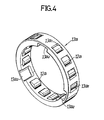
- the retainer 13a is provided with a plurality of roller-supporting holes 13a1 extending radially therethrough in corresponence with positions of the cam grooves 10a1, and the rollers 12a are retained within the roller-supporting holes 13a1 for slight movement in a radial direction.
- dowel-admission grooves are provided around an inner periphery of the retainer 13a at distances of 120° and opened into one side surface of the retainer 13a to extend axially.
- the dowel-admission grooves 13a2 are made to lie in the middle of the adjacent roller-supporting holes 13a1, thereby ensuring that the axial thickness of the retainer 13a is of a minimum level required for retaining the rollers 12a.
- a dowel 8a is projectingly provided on one side of the sleeve 8, so that it is removed from the dowel-admission groove 13a2 by the axial movement of the sleeve 8 through the spline 7.
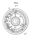
- the inner cam 10a and the retainer 13a are positioned in their states show in Fig.2, and each of the rollers 12a is centrally fitted in the can groove 10a1.
- a roller synchro mechanism for the second shift stage has a structure substantially symmetrical with and identical to a roller synchro mechanism for the first shift stage and hence, the duplicated description thereof is omitted by using reference characters with a suffix b attached thereto.
- the inner cam 10a and the retainer 13a are positioned in states shown in Fig.2 through the spline 11a, the rotary shaft 1, the spline 5, the boss 6, the spline 7, the dowel 8a of the sleeve 8, and the dowel-admission groove 13a2. Then, the rollers 12a retained in the retainer 13a are slightly moved radially inwardly within the roller-supporting holes 13a1 away from the roller abutment surface 3a2 of the gear 3a.
- the retainer 13a and the inner cam 10a can be relatively rotated slightly by a torque applied from the rotary shaft 1 or the gear 3a.
- rollers 12a are strongly urged radially outwardly within the roller-supporting holes 13a1 by the cam grooves 10a1 in the inner cam 10a to bear against the roller abutment surface 3a2 of the gear 3a. This causes the inner cam 10a and the gear 3a, and thus the rotary shaft 1 and the gear 3a to be brought into integral engagement with each other, thereby establishing the first shift stage. Conversely, if the sleeve 8 is moved in a direction of an arrow B, the rotary slaft 1 and the gear 3b are brought into integral engagement with each other by an action similar to that described above, thereby establishing the second shift stage.
- dowel-admission grooves 13a2′ and 13b2′ in retainers 13a′ and 13b′ in the prior art are provided on axes of rollers 12a′ and 12b′, respectively, whereas the dowel-admission grooves 13a2 and 13b2 in the present invention are provided between the circumferentially adjacent roller-supporting holes 13a1 and 13b1, respectively. Therefore, it is possible to provide a least but required axial thickness of the retainers 13a and 13b, resulting in a reduction in size of the roller synchro mechanisn.
- roller-abutment surfaces 3a2 and 3b2 are formed on the side of the gears 3a and 3b, whereas the cam grooves 10a1 and 10b1 are formed on the side of the inner cams 10a and 10b.
- Gears 3a and 3b in this embodiment have annular recesses 3a3 and 3b3 made in opposed side surfaces thereof, respectively, and retainers 13a and 13b retaining inner cams 10a and 10b and rollers 12a and 12b are contained within the recesses 3a3 and 3b3 made in the gear 3a and 3b, respectively.
- the inner cams 10a and 10b are formed integrally with the boss 6, because they cannot le spline-connected directly to the rotary shaft 1.
- the gears 3a or 3b in a first or second shift stage can be selectively brought into engagement with the rotary shaft 1 by moving the sleeve 8 axially to remove dowels 8a and 8b from dowel-admission grooves 13a2 and 13b2 in the retainers 13a and 13b, respectively.
- the retainers 13a and 13b retaining the inner cans 10a and 10b and the rollers 12a and 12b are contained in the recesses 3a3 and 3b3 made in the gears 3a and 3b, respectively and therefore, it is possible to substantially reduce the axial thickness of the gears 3aand 3b to further reduce the axial dimension of the roller synchro mechanism in cooperation with the disposition of the dowel-admission groove 13a2, 13b2 between the adjacent rollers 12a, 12b.
- Fig.6 is a sectinal view similar to Fig.1;
- Fig.7 is a sectional view taken along a line VII-VII in Fig.6;
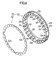
- Fig.8 is an enlarged exploded view of a retainer.
- a first shift-stage gear 521 is relatively rotatably carried through a needle bearing 51 on the rotary shaft 1 which constitutes an output shaft of a continuously variable transmission
- a second shift-stage gear 522 is also relatively rotatably carried likewise through the needle bearing 51 on the rotary shaft 1 at a location axially spaced apart from the gear 521 by a predetermined distance, between the two gears 521 and 522
- a sleeve 56 is axially slidably carried through a spline 55 around an outer periphery of a boss 54 connected over the rotary shaft 1 through spline 53, so that the axial movement of the sleeve 56 by a shift fork 57 causes the first shift-stage gear 521 or the second shift-stage gear 522 to be brought into integral engagement with the rotary shaft 1, thereby selectively establishing a first or second shift stage.
- the spline 55 and the sleeve 56 are engaged in a reces
- a recess is made in a side surface of the first shift-stage gear 521, and a ring-shaped inner cam 58 is integrally formed on a side of the boss 54 to lie within the recess.
- a large nunber of triangular cam grooves 58a are provided in an outer periphery of the inner can 58, and a large number of rollers 60 retained in a retainer 59 are disposed between the can grooves 58a and a roller abutment surface 52a around an outer periphery of the recess in the gear 521, respectively.
- the retainer 59 is a ring-shaped member relatively rotatably fitted in the recess in the gear 521 and comprised of two components: a body portion 61 and a cover plate 62.
- the body portion 61 is provided with roller-retaining grooves 61b defined between a large number of connections 61a to retain the rollers 60 for slight movement in a radial direction.
- each of the roller-retaining grooves 61b i.e., a surface opposed to an outer periphery of the roller 60 is formed into an arcuate surface having a radius of curvature larger than the radius of the roller 60, thereby a corner between the roller abutment surface 52a and the roller-retaining groove 61b becomes obtuse
- a projection 61c is formed on a side of the connection 61a, and the body portion 61 and the cover plate 62 are integrally coupled to each other by fitting each of the projections 61c in a caulking manner into corresponding one of holes 62a provided in the cover plate 62.
- dowel-admission grooves 59a are provided around an inner periphery of the retainer 59 at distances of 90 ° and opened into a side thereof closer to the cover plate 62 to extend axially.
- the roller-retaining groove 61b into an arcuate surface as described above, there is no fear that the roller contained in the roller-retaining groove 61b may be fallen to the outside, and therefore, the workability of assembling of the retainer 59 can be substantially improved.
- the roller-retaining groove 61b in the body portion 61 most requiring an accuracy is opened into the surface joined to the cover plate 62, the machining of the roller-retaining groove 61b can be easily carried out with a higher accuracy.
- Such retainer 59 is mounted between the roller abutment surface 52a around the outer periphery of the recess in the gear 521 and the cam groove 58a of the inner cam 58 and in this case, slide contact portions 61d are formed around the outer periphery of the body portion 61 of the retainer 59 and tightly fitted into the recess in the gear 521 in order to ensure that a proper frictional force is provided between the slide contact portions 61d and the recess in the gear 521 to causes the retainer 59a to be dragged by the gear 521.
- lubricating grooves 61e are provided around the outer periphery of the body portion 61 of the retainer 59, and a locking portion 61f is formed in the body portion 61 to abut against the side surface of the inner cam 58 in order to restrain the axial movement of the body portion 61.
- dowels 56a are projectingly provided on a side surface of the sleeve 56 at distances of 90°, so that the axial movement of the sleeve 56 through the spline 55 causes the dowel 56a to be brought into and out of engagement with the dowel-admission groove 59a.
- the inner cam 58 and the retainer 59 are positioned in their states shown in Fig.7, with each roller 60 being centrally fitted in the cam groove 58a.
- the roller synchro mechanism of this embodiment in a condition in which the sleeve 56 is in a neutral position shown in Fig.6 with the right dowel 56a thereof fitted in the dowel-admission groove 59a in the retainer 59 on the side of the gear 521, the inner cam 58 and the retainer 59 are positioned in their states shown in Fig.7. Consequently, the rollers 60 retained in the retainer 59 are in their states capable of moving within the roller-retaining grooves 61b. In such condition, the outer peripheral surface of the retainer 59 and the roller abutment surface 52a of the gear 521 are slipped relative to each other, so that the transmission of a torque between the rotary shaft 1 and the gear 521 is cut off.
- the left dowel 56a of the sleeve 56 is also fitted in the dowel-admission groove 59a in the retainer 59 for the second shift-stage gear 522, so that the transmission of a torque between the rotary shaft 1 and the gear 522 is also cut off.
- the retainer 59 and the inner cam 58 are relatively rotated slightly by a torque applied from the rotary shaft 1 or the gear 521, causing the rollers 60 to be strongly urged radially outwardly within the roller-retaining grooves 61b by the cam grooves 58a in the inner cam 58 to bear against the roller abutment surface 52a of the gear 521.
- This causes an integral engagement between the inner cam 58 and the gear 521 and thus between the rotary shaft 1 and the gear 521 to establish a first shift state.
- the sleeve 56 is moved in a direction of an arrow B, the rotary shaft 1 and the gear 522 are brought into integral engagement with each other by an action similar to that described above to establish a second shift stage.
- roller synchro mechanism has been provided between the first and second shift stages in the embodiments, it can be, of course, provided in another shift stage.
- dowel-admission groove 13a2, 13b2, in tie second embodiment has been made between the rollers 12a, 12b of the retainer 13a, 13b as in the first embodiment, such dowel-admission groove 13a2, 13b2 may be made on an axis of the roller 12a, 12b as in the prior art, and the inner cam 10a, 10b, the rollers 12a, 12b and the retainer 13a, 13b may be disposed in the recess 3a3, 3b3 made in the gear 3a, 3b.
- Such ameasure makes it possible to provide a reduction in axial dimension of the roller synchro mechanism.
Landscapes
- Engineering & Computer Science (AREA)
- General Engineering & Computer Science (AREA)
- Mechanical Engineering (AREA)
- Mechanical Operated Clutches (AREA)
- Structure Of Transmissions (AREA)
Applications Claiming Priority (4)
| Application Number | Priority Date | Filing Date | Title |
|---|---|---|---|
| JP97098/90 | 1990-04-12 | ||
| JP2097098A JP2900173B2 (ja) | 1990-04-12 | 1990-04-12 | ローラシンクロ機構 |
| JP336580/90 | 1990-11-30 | ||
| JP2336580A JP2849949B2 (ja) | 1990-11-30 | 1990-11-30 | ローラシンクロ機構のリテーナ構造 |
Publications (3)
| Publication Number | Publication Date |
|---|---|
| EP0452150A2 true EP0452150A2 (fr) | 1991-10-16 |
| EP0452150A3 EP0452150A3 (en) | 1992-01-22 |
| EP0452150B1 EP0452150B1 (fr) | 1997-10-08 |
Family
ID=26438303
Family Applications (1)
| Application Number | Title | Priority Date | Filing Date |
|---|---|---|---|
| EP91303265A Expired - Lifetime EP0452150B1 (fr) | 1990-04-12 | 1991-04-12 | Mécanisme de synchronisation à rouleaux |
Country Status (3)
| Country | Link |
|---|---|
| US (1) | US5178250A (fr) |
| EP (1) | EP0452150B1 (fr) |
| DE (1) | DE69127848T2 (fr) |
Cited By (1)
| Publication number | Priority date | Publication date | Assignee | Title |
|---|---|---|---|---|
| EP2166253A1 (fr) * | 2008-09-23 | 2010-03-24 | Xtrac Limited | Boîte de vitesse |
Families Citing this family (15)
| Publication number | Priority date | Publication date | Assignee | Title |
|---|---|---|---|---|
| US5301565A (en) * | 1987-02-26 | 1994-04-12 | Weismann Peter H | Transmission |
| GB9612778D0 (en) * | 1996-06-19 | 1996-08-21 | Eaton Corp | System and method for preventing gear hopout in a compound transmission |
| GB9612787D0 (en) * | 1996-06-19 | 1996-08-21 | Eaton Corp | System for preventing gear hopout in a compound transmission |
| US5927456A (en) * | 1996-11-01 | 1999-07-27 | Ntn Corporation | Two-way over-running clutch assembly |
| US5924535A (en) * | 1997-08-11 | 1999-07-20 | Eaton Corporation | Pin-type synchronizer with self-energizing ramp means providing force for maintaining engagement of jaw members |
| WO2001027485A1 (fr) * | 1999-10-13 | 2001-04-19 | Preload International Limited | Embrayage a galets |
| GB0006705D0 (en) * | 2000-03-20 | 2000-05-10 | Ricardo Mtc Limited | Gearboxes |
| US20060191763A1 (en) * | 2003-10-20 | 2006-08-31 | Joki Mark A | Clutching device |
| US7384366B2 (en) * | 2004-03-12 | 2008-06-10 | Borgwarner Inc. | Transfer case with torque synchronizer clutching |
| US7415905B2 (en) * | 2005-01-07 | 2008-08-26 | Gm Global Technology Operations, Inc. | Vehicular transmissions utilizing slipper ring clutch control |
| GB2426302A (en) * | 2005-05-21 | 2006-11-22 | Xtrac Ltd | Gearbox |
| CA2669278C (fr) * | 2006-10-31 | 2015-04-28 | Magna Powertrain Usa, Inc. | Systeme d'engrenage synchronise |
| US9080621B2 (en) | 2009-09-04 | 2015-07-14 | Borgwarner Inc. | Freewheeling synchronizer |
| US9995350B2 (en) * | 2015-08-11 | 2018-06-12 | Schaeffler Technologies AG & Co. KG | Switchable one way clutch including selector bracket |
| DE102020107957A1 (de) * | 2020-03-23 | 2021-03-18 | Schaeffler Technologies AG & Co. KG | Freilauf Schalteinheit mit einer Rotationsachse für ein Getriebe |
Family Cites Families (7)
| Publication number | Priority date | Publication date | Assignee | Title |
|---|---|---|---|---|
| DE576907C (de) * | 1932-11-03 | 1933-05-20 | Soc D Const Des Batignolles | Freilaufkupplung fuer Ausgleichgetriebe von Kraftfahrzeugen |
| DE1400651A1 (de) * | 1960-06-14 | 1968-10-17 | Hy Torq Products Corp | Kraft-UEbertragungs-Mechanismus |
| US3426874A (en) * | 1967-09-25 | 1969-02-11 | Int Harvester Co | Self-energizing synchronizing clutch |
| DE1946140A1 (de) * | 1968-09-11 | 1970-03-26 | Hy Torq Corp | Differentialgetriebe |
| US3949848A (en) * | 1974-11-01 | 1976-04-13 | Borg-Warner Corporation | Gear changing mechanism |
| US4111288A (en) * | 1976-12-30 | 1978-09-05 | Borg-Warner Corporation | Gear changing mechanism |
| US4817451A (en) * | 1987-02-26 | 1989-04-04 | Weismann Peter H | Control mechanism for selective engagement of a free wheeling engagement mechanism |
-
1991
- 1991-04-12 EP EP91303265A patent/EP0452150B1/fr not_active Expired - Lifetime
- 1991-04-12 US US07/685,471 patent/US5178250A/en not_active Expired - Fee Related
- 1991-04-12 DE DE69127848T patent/DE69127848T2/de not_active Expired - Fee Related
Cited By (2)
| Publication number | Priority date | Publication date | Assignee | Title |
|---|---|---|---|---|
| EP2166253A1 (fr) * | 2008-09-23 | 2010-03-24 | Xtrac Limited | Boîte de vitesse |
| US8424405B2 (en) | 2008-09-23 | 2013-04-23 | Xtrac Limited | Gearbox |
Also Published As
| Publication number | Publication date |
|---|---|
| US5178250A (en) | 1993-01-12 |
| DE69127848D1 (de) | 1997-11-13 |
| DE69127848T2 (de) | 1998-01-29 |
| EP0452150B1 (fr) | 1997-10-08 |
| EP0452150A3 (en) | 1992-01-22 |
Similar Documents
| Publication | Publication Date | Title |
|---|---|---|
| EP0452150A2 (fr) | Mécanisme de synchronisation à rouleaux | |
| EP0369597B1 (fr) | Méthode d'assemblage et assemblage d'un porte-satelittes | |
| US20040025618A1 (en) | Locking device with transmission gears | |
| EP0167319A1 (fr) | Mécanisme de synchronisme à blocage pour embrayage | |
| JP2001512219A (ja) | クラッチ | |
| JP2016187981A (ja) | 四輪駆動車の差動制限装置 | |
| EP0465080B1 (fr) | Synchroniseur auto-renforçant | |
| US5024308A (en) | One-way clutch and holder for torque transmitting members thereof | |
| EP0753682B1 (fr) | Embrayage différentiel bidirectionnel | |
| US8544625B2 (en) | Overrunning bi-directional clutch as gear synchronizer and coupler | |
| CN101384830B (zh) | 变速器的同步装置 | |
| KR950005878B1 (ko) | 변속기의 동기 스프링 핀 | |
| US6530461B2 (en) | Clutch unit | |
| EP0195519A1 (fr) | Mécanisme de syndro d'engrenage dans une transmission de couple | |
| EP0144962B1 (fr) | Unité de synchro d'engrenage pour transmission de couple | |
| JP2900173B2 (ja) | ローラシンクロ機構 | |
| KR100631294B1 (ko) | 2 방향 차동 클러치 | |
| JPH0533782Y2 (fr) | ||
| JP2907973B2 (ja) | 変速機の同期装置 | |
| JPH0716105Y2 (ja) | 変速機の同期噛合装置 | |
| JP2847618B2 (ja) | 出力軸を入力軸によって回転可能な回転伝達装置 | |
| JP2001512218A (ja) | 切換クラッチ | |
| JP2000110848A (ja) | シンクロメッシュ装置 | |
| US5549188A (en) | Split pin for transmission synchronizer assembly | |
| JPH052847B2 (fr) |
Legal Events
| Date | Code | Title | Description |
|---|---|---|---|
| PUAI | Public reference made under article 153(3) epc to a published international application that has entered the european phase |
Free format text: ORIGINAL CODE: 0009012 |
|
| AK | Designated contracting states |
Kind code of ref document: A2 Designated state(s): DE FR GB IT |
|
| PUAL | Search report despatched |
Free format text: ORIGINAL CODE: 0009013 |
|
| AK | Designated contracting states |
Kind code of ref document: A3 Designated state(s): DE FR GB IT |
|
| 17P | Request for examination filed |
Effective date: 19920408 |
|
| 17Q | First examination report despatched |
Effective date: 19920810 |
|
| GRAG | Despatch of communication of intention to grant |
Free format text: ORIGINAL CODE: EPIDOS AGRA |
|
| GRAH | Despatch of communication of intention to grant a patent |
Free format text: ORIGINAL CODE: EPIDOS IGRA |
|
| GRAH | Despatch of communication of intention to grant a patent |
Free format text: ORIGINAL CODE: EPIDOS IGRA |
|
| GRAA | (expected) grant |
Free format text: ORIGINAL CODE: 0009210 |
|
| AK | Designated contracting states |
Kind code of ref document: B1 Designated state(s): DE FR GB IT |
|
| PG25 | Lapsed in a contracting state [announced via postgrant information from national office to epo] |
Ref country code: FR Free format text: THE PATENT HAS BEEN ANNULLED BY A DECISION OF A NATIONAL AUTHORITY Effective date: 19971008 |
|
| REF | Corresponds to: |
Ref document number: 69127848 Country of ref document: DE Date of ref document: 19971113 |
|
| ET | Fr: translation filed | ||
| PLBE | No opposition filed within time limit |
Free format text: ORIGINAL CODE: 0009261 |
|
| STAA | Information on the status of an ep patent application or granted ep patent |
Free format text: STATUS: NO OPPOSITION FILED WITHIN TIME LIMIT |
|
| 26N | No opposition filed | ||
| REG | Reference to a national code |
Ref country code: FR Ref legal event code: ST |
|
| PGFP | Annual fee paid to national office [announced via postgrant information from national office to epo] |
Ref country code: GB Payment date: 19990415 Year of fee payment: 9 |
|
| PGFP | Annual fee paid to national office [announced via postgrant information from national office to epo] |
Ref country code: DE Payment date: 19990419 Year of fee payment: 9 |
|
| PG25 | Lapsed in a contracting state [announced via postgrant information from national office to epo] |
Ref country code: GB Free format text: LAPSE BECAUSE OF NON-PAYMENT OF DUE FEES Effective date: 20000412 |
|
| GBPC | Gb: european patent ceased through non-payment of renewal fee |
Effective date: 20000412 |
|
| PG25 | Lapsed in a contracting state [announced via postgrant information from national office to epo] |
Ref country code: DE Free format text: LAPSE BECAUSE OF NON-PAYMENT OF DUE FEES Effective date: 20010201 |
|
| PG25 | Lapsed in a contracting state [announced via postgrant information from national office to epo] |
Ref country code: IT Free format text: LAPSE BECAUSE OF NON-PAYMENT OF DUE FEES;WARNING: LAPSES OF ITALIAN PATENTS WITH EFFECTIVE DATE BEFORE 2007 MAY HAVE OCCURRED AT ANY TIME BEFORE 2007. THE CORRECT EFFECTIVE DATE MAY BE DIFFERENT FROM THE ONE RECORDED. Effective date: 20050412 |