EP0452171A1 - Anschlussvorrichtung für die Seele eines Koaxkabels - Google Patents
Anschlussvorrichtung für die Seele eines Koaxkabels Download PDFInfo
- Publication number
- EP0452171A1 EP0452171A1 EP91400692A EP91400692A EP0452171A1 EP 0452171 A1 EP0452171 A1 EP 0452171A1 EP 91400692 A EP91400692 A EP 91400692A EP 91400692 A EP91400692 A EP 91400692A EP 0452171 A1 EP0452171 A1 EP 0452171A1
- Authority
- EP
- European Patent Office
- Prior art keywords
- recess
- core
- pilot hole
- lip
- edge
- Prior art date
- Legal status (The legal status is an assumption and is not a legal conclusion. Google has not performed a legal analysis and makes no representation as to the accuracy of the status listed.)
- Granted
Links
- 239000004020 conductor Substances 0.000 claims abstract description 7
- 238000003780 insertion Methods 0.000 claims abstract description 6
- 230000037431 insertion Effects 0.000 claims abstract description 6
- 230000001154 acute effect Effects 0.000 claims description 8
- 230000004323 axial length Effects 0.000 claims description 4
- 239000000463 material Substances 0.000 abstract description 4
- 239000002184 metal Substances 0.000 description 13
- 230000001846 repelling effect Effects 0.000 description 2
- 230000000712 assembly Effects 0.000 description 1
- 238000000429 assembly Methods 0.000 description 1
- 238000007373 indentation Methods 0.000 description 1
- 238000004519 manufacturing process Methods 0.000 description 1
- 238000000034 method Methods 0.000 description 1
- 230000000717 retained effect Effects 0.000 description 1
- 238000003466 welding Methods 0.000 description 1
Images
Classifications
-
- H—ELECTRICITY
- H01—ELECTRIC ELEMENTS
- H01R—ELECTRICALLY-CONDUCTIVE CONNECTIONS; STRUCTURAL ASSOCIATIONS OF A PLURALITY OF MUTUALLY-INSULATED ELECTRICAL CONNECTING ELEMENTS; COUPLING DEVICES; CURRENT COLLECTORS
- H01R4/00—Electrically-conductive connections between two or more conductive members in direct contact, i.e. touching one another; Means for effecting or maintaining such contact; Electrically-conductive connections having two or more spaced connecting locations for conductors and using contact members penetrating insulation
- H01R4/28—Clamped connections, spring connections
- H01R4/50—Clamped connections, spring connections utilising a cam, wedge, cone or ball also combined with a screw
-
- H—ELECTRICITY
- H01—ELECTRIC ELEMENTS
- H01R—ELECTRICALLY-CONDUCTIVE CONNECTIONS; STRUCTURAL ASSOCIATIONS OF A PLURALITY OF MUTUALLY-INSULATED ELECTRICAL CONNECTING ELEMENTS; COUPLING DEVICES; CURRENT COLLECTORS
- H01R9/00—Structural associations of a plurality of mutually-insulated electrical connecting elements, e.g. terminal strips or terminal blocks; Terminals or binding posts mounted upon a base or in a case; Bases therefor
- H01R9/03—Connectors arranged to contact a plurality of the conductors of a multiconductor cable, e.g. tapping connections
- H01R9/05—Connectors arranged to contact a plurality of the conductors of a multiconductor cable, e.g. tapping connections for coaxial cables
Definitions
- the invention relates to a device for connecting the core of a coaxial cable of the type which includes a pin which is inserted into the recess of a core, said recess not being, more particularly, not directly accessible, the recess connecting to a region of cross section greater than that of the recess, the junction zone between said region and the recess comprising a sharp edge.
- Such a device can, in particular, be used for the connection of an antenna to a car radio, and be part of a cable connection assembly.
- connection assemblies for coaxial cable comprise a metal part intended to be electrically connected to the metal braid of the coaxial cable, this part generally comprising, on the one hand, a tubular appendage intended to receive the end of the coaxial cable and a device for connecting the cable core comprising a metal pin which is inserted into the recess of a core. The pin clamps the cable core against the wall of the recess.
- the pins generally used are elongated metal parts of circular or polygonal cross section and the ends of which can be rounded, conical or pyramidal.
- the cross section of the recess has a shape and dimensions corresponding to the shape of the pin.
- connection of the cable core and the pin poses a particular problem because the core consists of a thin wire, the diameter of which can be of the order of 0.3 mm, in particular when it is a question of 'a floating soul inside a sheath called “sheath air ", without being fixed therein.
- the core tends to escape and re-enter the sheath so that the connection is not made or is made in bad conditions.
- connection device for an electric cable comprising a metal ring with an edge. lively, ring which can be screwed onto a threaded pin bevelled at its end.
- the conductive cable, surrounded by its insulating sheath, is engaged in the metal ring and, when this ring is screwed onto the spindle, the edge cuts the sheath of the insulating cable and establishes a conductive connection with the metal cable.
- the object of the invention is, above all, to provide a connection device of the kind defined above which makes it possible to connect seamlessly to a pin, in a reliable manner, the core of a coaxial cable, even though the recess of the core is not directly accessible, being located at the bottom of a dwelling.
- the invention also aims to provide such a connection device whose mounting operations can be made easily automatic, for mass production, while ensuring high reliability of the connection made between the pin and the cable core coaxial.
- a connection device of the kind defined above is characterized in that it is arranged to allow the spindle to be engaged in the recess by a translational movement, after insertion of the stripped core into said recess so that the soul is stuck in the recess; that the core is insulating, made of plastic of appropriate hardness; that the aforesaid cross-sectional region greater than that of the recess is constituted by a pilot hole provided in the core and coaxial with the recess; that the sharp edge is formed by the top of a lip provided in the core at the junction of the recess and the pilot hole, the lip having faces forming an angle; the assembly being such that, during the positioning of the spindle in the recess, the core of the conductor becomes embedded in the sharp edge by deformation of the plastic material of the core, the core being thus braked, without risk of being damaged, by said sharp deformed edge.
- the pilot hole may have an axial length greater than that of the recess.
- the spindle has a smooth surface in the longitudinal direction corresponding to the direction of introduction by translation of the spindle into the recess. The risk of catching and repelling the core during the introduction is thus reduced.
- the pin has tapered ends.
- the angle at the top of these conical ends is preferably between 30 ° and 45 °.
- the edge of the recess may consist of the edge of a shoulder perpendicular to the common axis of the recess and of the pilot hole connecting the wall of the recess to the pilot hole, the faces of the lip being formed by said shoulder and by the area adjacent to the wall of the recess and forming between them, in section in an axial plane, an angle of 90 °.
- the lip is constituted by a projection forming an acute angle and directed towards the common axis of the recess and the pilot hole, the sharp edge forming the top of the projection.
- the faces of the lip can be formed by a shoulder perpendicular to the common axis and by a frustoconical wall connecting the edge of said shoulder and the wall of the recess.
- the lip is constituted by a projection forming an acute angle directed into the pilot hole parallel to the common axis of the recess and the pilot hole.
- the faces of the lip can be formed by an extension in the pilot hole of the wall of the recess and by a frustoconical wall connecting the edge of said extension to a shoulder perpendicular to the common axis.
- the core of the coaxial cable is applied against the sharp edge of the plastic core, of suitable hardness, so as to become embedded therein; the core is thus braked by the edge and remains in place during the introduction of the spindle, which has no roughness capable of catching the core and repelling it.
- a core length is used such that its end remains in the pilot hole, but is sufficient so that the core when the pin is driven in, can tilt in the pilot hole.
- This significant length of the core exceeding the recess is not a problem in the case where the core is contained in a metal sleeve which is grounded because, due to the significant length of the pilot hole, the soul cannot come into contact with the sleeve. This avoids the risks of a short-circuit to ground or any other electrical anomaly due to the fact that the distance between the core and the ground would not be constant.
- the invention consists, apart from the arrangements set out above, of a certain number of other arrangements which will be more explicitly discussed below in connection with an exemplary embodiment described with reference to the attached drawing, but which is by no means limiting.
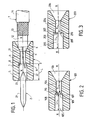
- Figure 1 of this drawing is a schematic view in axial section of a first embodiment of the device according to the invention.
- Figures 2 and 3 are schematic views in axial section showing two different embodiments of the lips forming the sharp edges according to the invention.
- the device for connecting the core 11 of a coaxial cable 1 shown in FIG. 1 comprises a metal pin 2 and an insulating core 3 made of plastic material in which are formed a recess 4 and a pilot hole 5.
- the coaxial cable 1 consists of a core 11, one end of which is exposed, core 11 surrounded by a concentric insulating sheath 12, then a metal braid 13 and an outer insulating layer 14.
- the insulating sheath 12 is an air sheath, that is to say that the core 11 floats inside the insulating sheath 12 which contains air.
- the core 11 is held in the air duct by a plastic rod (not shown) arranged in a helix with a very wide pitch.
- the core 3 is insulating, made of plastic of appropriate hardness.
- the insulating core 3 has, according to the embodiment shown, a cylindrical shape of circular section and it is crossed by the axial recess 4, cylindrical with circular section, which is connected on the insertion side of the cable 1 to a tapered opening 6 and insertion side of the pin 2 to the pilot hole 5 which, according to the embodiment shown, is cylindrical with circular section.
- the axial length L of the pilot hole 5 is greater than the axial length h of the recess 4.
- the pilot hole 5, the recess 4 and the frustoconical opening 6 have a common axis X-X.
- the junction between the pilot hole 5 and the recess 4 is made by an annular shoulder 7, the plane of which is perpendicular to the common axis X-X.
- An annular lip 8 is formed, in the core 3, at the junction of the recess 4 and the pilot hole 5.
- This lip 8 has faces formed by the shoulder 7 and the area adjacent to the inner wall of the recess 4. These faces form between them an angle equal to 90 ° in the case of FIG. 1.
- a sharp edge 9 is formed by the top of this lip 8.
- the pin 2 consists of a metal cylinder 21 provided at each of its ends with a conical part 22, the junction between the cylindrical part 21 and the conical part 22 being effected by means of a rounded surface 23.
- the spindle 2 has a smooth surface in the longitudinal direction parallel to the axis X-X, corresponding to the direction of introduction by translation of the spindle into the recess 4. In this way the spindle has no roughness or any sharp angle.
- the angle at the top of the conical part is advantageously from 30 ° to 45 °.
- connection device operates as described below.
- the stripped part of the core 11 of the cable 1 is introduced through the frustoconical opening 6 into the recess 4 then the pilot hole 5 until its end slightly exceeds the entry opening of the pilot hole 5.
- the pin 2 is then introduced by a conical end 22 into the pilot cylindrical hole 5.
- the pin by sinking into the pilot hole 5 laterally pushes the core 11 by tilting it towards the side wall of the pilot hole 5 and when the cylindrical part 21 of the pin 2 reaches the level of the shoulder 7, it applies the core 11 against the sharp edge 9 and encrusts it in said edge.
- the cylindrical part 21 of the spindle comes to wedge the core 11 against the internal wall of the recess 4.
- the core 11 is thus held in place and the electrical contact between the core 11 and the pin 2 is established.
- connection device is thus arranged to allow the pin 2 to be engaged and wedged in the recess by a translational movement, after insertion of the stripped core into said recess 4.
- the ends of the spindle 2 are conical so as to ensure, at the start of its introduction, the inlay of the core 11 in the lip 9 of the core 3 and the braking of this core by said core, whose plastic material is chosen with an appropriate hardness to allow this encrustation without injuring the core 11, and to ensure good braking.
- a spindle to slightly rounded cylindrical end could be introduced directly into the recess 4, without risk of pushing the core 11 sufficiently braked.
- FIG. 2 represents an embodiment of an insulating core 103 in which the lip 108 forms an acute angle and projects in the direction of the axis of the insulating core.
- the insulating core 103 is pierced with a frustoconical opening 106, a recess 104 and a pilot hole 105 having a common axis X-X.
- the lip 108 is circular and its faces are formed by an annular shoulder 107 perpendicular to the common axis XX and by a frustoconical wall 110 connecting the edge of the shoulder 107 to the internal wall of the recess 104.
- the angle formed between 107 and 110, in section through a longitudinal plane, is an acute angle.
- the sharp edge 109 is constituted by the circle common to the shoulder 107 and to the frustoconical wall 110.
- the lip 108 has a certain elasticity, which allows it to be erased during the introduction of the spindle and it has the advantage of facilitating the encrustation of the cable core in the sharp edge 109.
- FIG. 3 shows another embodiment of an insulating core 203 in which the lip 208 forms an acute angle and projects into the pilot hole 205 parallel to the axis XX of an insulating core 203.
- the insulating core 203 is pierced, in order, with a frustoconical opening 206 for the introduction of the cable, with a recess 204 in which the pin jams the core of the cable and with a pilot hole 205.
- the opening 206 , recess 204 and the pilot hole 205 have a common axis XX.
- the lip 208 is circular and its faces are formed by the inner wall of the recess 204 and by a frustoconical wall 210 connecting the inner wall of the recess 204 to a shoulder 207 perpendicular to the common axis XX; in section in an axial longitudinal plane, the angle between the interior wall of the recess 204 and the oblique wall 210 is an acute angle.
- the sharp edge 209 is formed by the circle common to the interior wall of the recess 204 and to the oblique wall 210.
- the lip 8, 108, 208 may not be continuous on a circle, but have indentations.
Landscapes
- Coupling Device And Connection With Printed Circuit (AREA)
- Processing Of Terminals (AREA)
- Cable Accessories (AREA)
- Communication Cables (AREA)
- Non-Reversible Transmitting Devices (AREA)
- Snaps, Bayonet Connections, Set Pins, And Snap Rings (AREA)
- Insertion Pins And Rivets (AREA)
- Multi-Conductor Connections (AREA)
Applications Claiming Priority (2)
| Application Number | Priority Date | Filing Date | Title |
|---|---|---|---|
| FR9003953 | 1990-03-28 | ||
| FR9003953A FR2660488B1 (fr) | 1990-03-28 | 1990-03-28 | Dispositif de raccordement de l'ame d'un cable coaxial, plus particulierement d'une ame contenue dans une gaine d'air. |
Publications (2)
| Publication Number | Publication Date |
|---|---|
| EP0452171A1 true EP0452171A1 (de) | 1991-10-16 |
| EP0452171B1 EP0452171B1 (de) | 1994-11-23 |
Family
ID=9395197
Family Applications (1)
| Application Number | Title | Priority Date | Filing Date |
|---|---|---|---|
| EP91400692A Expired - Lifetime EP0452171B1 (de) | 1990-03-28 | 1991-03-14 | Anschlussvorrichtung für die Seele eines Koaxkabels |
Country Status (5)
| Country | Link |
|---|---|
| EP (1) | EP0452171B1 (de) |
| AT (1) | ATE114387T1 (de) |
| DE (1) | DE69105232T2 (de) |
| ES (1) | ES2064055T3 (de) |
| FR (1) | FR2660488B1 (de) |
Cited By (2)
| Publication number | Priority date | Publication date | Assignee | Title |
|---|---|---|---|---|
| FR2687020A1 (fr) * | 1992-02-05 | 1993-08-06 | Mecaniplast | Procede de fixation d'un cable a un element de raccordement et appareil de fixation correspondant. |
| EP1180823A3 (de) * | 2000-08-09 | 2003-01-29 | Phoenix Contact GmbH & Co. KG | Kabelanschluss- oder -verbindungseinrichtung |
Citations (2)
| Publication number | Priority date | Publication date | Assignee | Title |
|---|---|---|---|---|
| FR1495934A (fr) * | 1966-10-05 | 1967-09-22 | Raccord de câbles électriques | |
| US4091233A (en) * | 1976-08-23 | 1978-05-23 | Berman Alfred J | Electrical connector and method of connecting an electrical cable to same |
-
1990
- 1990-03-28 FR FR9003953A patent/FR2660488B1/fr not_active Expired - Fee Related
-
1991
- 1991-03-14 EP EP91400692A patent/EP0452171B1/de not_active Expired - Lifetime
- 1991-03-14 DE DE69105232T patent/DE69105232T2/de not_active Expired - Fee Related
- 1991-03-14 ES ES91400692T patent/ES2064055T3/es not_active Expired - Lifetime
- 1991-03-14 AT AT91400692T patent/ATE114387T1/de active
Patent Citations (2)
| Publication number | Priority date | Publication date | Assignee | Title |
|---|---|---|---|---|
| FR1495934A (fr) * | 1966-10-05 | 1967-09-22 | Raccord de câbles électriques | |
| US4091233A (en) * | 1976-08-23 | 1978-05-23 | Berman Alfred J | Electrical connector and method of connecting an electrical cable to same |
Cited By (2)
| Publication number | Priority date | Publication date | Assignee | Title |
|---|---|---|---|---|
| FR2687020A1 (fr) * | 1992-02-05 | 1993-08-06 | Mecaniplast | Procede de fixation d'un cable a un element de raccordement et appareil de fixation correspondant. |
| EP1180823A3 (de) * | 2000-08-09 | 2003-01-29 | Phoenix Contact GmbH & Co. KG | Kabelanschluss- oder -verbindungseinrichtung |
Also Published As
| Publication number | Publication date |
|---|---|
| ATE114387T1 (de) | 1994-12-15 |
| ES2064055T3 (es) | 1995-01-16 |
| FR2660488B1 (fr) | 1994-04-08 |
| FR2660488A1 (fr) | 1991-10-04 |
| EP0452171B1 (de) | 1994-11-23 |
| DE69105232T2 (de) | 1995-04-20 |
| DE69105232D1 (de) | 1995-01-05 |
Similar Documents
| Publication | Publication Date | Title |
|---|---|---|
| EP0914689B1 (de) | Verfahren zum verbinden von koaxialkabeln und dazu gehöriger stecker | |
| FR2758662A1 (fr) | Element de connecteur electrique coaxial a contact mobile et connecteur electrique coaxial comprenant un tel element de connecteur | |
| EP0491626A1 (de) | Elektrischer Koaxialverbinder | |
| WO2010020733A1 (fr) | Dispositif de connexion entre un cable electrique et une structure conductrice, notamment pour circuit de retour de courant. | |
| CA2697588A1 (fr) | Cosse pour connexion electrique et son procede d'assemblage | |
| EP0646998B1 (de) | Crimpwerkzeug zum Verbinden eines elektrischen Kabels mit einem Endstück | |
| FR2508729A1 (fr) | Connecteur pour cables electriques | |
| EP0500466B1 (de) | Verschluss für die Kontaktaufnahme eines elektrischen oder optischen Steckverbinders | |
| EP1039587A1 (de) | Steckerteil bestimmt für Montage auf einem elektrischen Kabel mit einem schraubenförmig gewellten Aussenleiter und Verfahren zur Montage | |
| EP0452171B1 (de) | Anschlussvorrichtung für die Seele eines Koaxkabels | |
| EP0132208A1 (de) | Abspannklemme für isolierte Tragseile mit mehreren Leitern | |
| FR2633103A1 (fr) | Embout de cablage | |
| FR2664751A1 (fr) | Systeme de mise en contact des conducteurs interieurs d'un cable coaxial et d'une fiche coaxiale, et dispositif pour le montage de ce systeme. | |
| FR2579836A1 (fr) | Embout pour conducteur electrique et son procede de fabrication | |
| CH631293A5 (fr) | Contact electrique. | |
| FR2794902A1 (fr) | Connecteur de derivation compact d'au moins un cable de derivation de neutre sur un cable principal de neutre et mise a la terre simultanee | |
| FR2594263A1 (fr) | Connecteur electrique comprenant au moins une douille et une broche, et procede de fabrication de la broche. | |
| EP0172779B1 (de) | Mehrpoliger elektrischer Verbinder | |
| FR2600217A1 (fr) | Connecteur de piquage cable coaxial et obturateur de substitution correspondant | |
| FR3058580A1 (fr) | Dispositif de connexion electrique | |
| FR3033672A1 (fr) | Contact femelle comprenant un ressort | |
| FR2722035A1 (fr) | Dispositif de connexion pour enceinte a decharge, et enceinte a decharge et cordon d'alimentation permettant la mise ein oeuvre de ce dispositif de connexion | |
| EP0093056B1 (de) | Elektrisches Verbindungsgerät | |
| FR2596588A1 (fr) | Contact femelle a douille fendue pour connecteur electrique | |
| EP1612890B1 (de) | Verbindungsteil für ein elektrisches Kabel, insbesondere für Mittelspannung |
Legal Events
| Date | Code | Title | Description |
|---|---|---|---|
| PUAI | Public reference made under article 153(3) epc to a published international application that has entered the european phase |
Free format text: ORIGINAL CODE: 0009012 |
|
| AK | Designated contracting states |
Kind code of ref document: A1 Designated state(s): AT BE CH DE DK ES FR GB GR IT LI LU NL SE |
|
| 17P | Request for examination filed |
Effective date: 19911018 |
|
| 17Q | First examination report despatched |
Effective date: 19940308 |
|
| GRAA | (expected) grant |
Free format text: ORIGINAL CODE: 0009210 |
|
| AK | Designated contracting states |
Kind code of ref document: B1 Designated state(s): AT BE CH DE DK ES FR GB GR IT LI LU NL SE |
|
| PG25 | Lapsed in a contracting state [announced via postgrant information from national office to epo] |
Ref country code: NL Effective date: 19941123 Ref country code: GR Free format text: LAPSE BECAUSE OF FAILURE TO SUBMIT A TRANSLATION OF THE DESCRIPTION OR TO PAY THE FEE WITHIN THE PRESCRIBED TIME-LIMIT Effective date: 19941123 Ref country code: DK Effective date: 19941123 Ref country code: AT Effective date: 19941123 |
|
| REF | Corresponds to: |
Ref document number: 114387 Country of ref document: AT Date of ref document: 19941215 Kind code of ref document: T |
|
| ITF | It: translation for a ep patent filed | ||
| REF | Corresponds to: |
Ref document number: 69105232 Country of ref document: DE Date of ref document: 19950105 |
|
| REG | Reference to a national code |
Ref country code: ES Ref legal event code: FG2A Ref document number: 2064055 Country of ref document: ES Kind code of ref document: T3 |
|
| EAL | Se: european patent in force in sweden |
Ref document number: 91400692.9 |
|
| GBT | Gb: translation of ep patent filed (gb section 77(6)(a)/1977) |
Effective date: 19950221 |
|
| PG25 | Lapsed in a contracting state [announced via postgrant information from national office to epo] |
Ref country code: LU Free format text: LAPSE BECAUSE OF NON-PAYMENT OF DUE FEES Effective date: 19950331 Ref country code: LI Effective date: 19950331 Ref country code: CH Effective date: 19950331 |
|
| NLV1 | Nl: lapsed or annulled due to failure to fulfill the requirements of art. 29p and 29m of the patents act | ||
| PLBE | No opposition filed within time limit |
Free format text: ORIGINAL CODE: 0009261 |
|
| STAA | Information on the status of an ep patent application or granted ep patent |
Free format text: STATUS: NO OPPOSITION FILED WITHIN TIME LIMIT |
|
| 26N | No opposition filed | ||
| REG | Reference to a national code |
Ref country code: CH Ref legal event code: PL |
|
| PGFP | Annual fee paid to national office [announced via postgrant information from national office to epo] |
Ref country code: GB Payment date: 19960308 Year of fee payment: 6 |
|
| PGFP | Annual fee paid to national office [announced via postgrant information from national office to epo] |
Ref country code: ES Payment date: 19960320 Year of fee payment: 6 |
|
| PGFP | Annual fee paid to national office [announced via postgrant information from national office to epo] |
Ref country code: SE Payment date: 19960325 Year of fee payment: 6 |
|
| PGFP | Annual fee paid to national office [announced via postgrant information from national office to epo] |
Ref country code: FR Payment date: 19960329 Year of fee payment: 6 |
|
| PGFP | Annual fee paid to national office [announced via postgrant information from national office to epo] |
Ref country code: BE Payment date: 19960412 Year of fee payment: 6 |
|
| PGFP | Annual fee paid to national office [announced via postgrant information from national office to epo] |
Ref country code: DE Payment date: 19960430 Year of fee payment: 6 |
|
| PG25 | Lapsed in a contracting state [announced via postgrant information from national office to epo] |
Ref country code: GB Effective date: 19970314 |
|
| PG25 | Lapsed in a contracting state [announced via postgrant information from national office to epo] |
Ref country code: SE Effective date: 19970315 Ref country code: ES Free format text: LAPSE BECAUSE OF NON-PAYMENT OF DUE FEES Effective date: 19970315 |
|
| PG25 | Lapsed in a contracting state [announced via postgrant information from national office to epo] |
Ref country code: BE Effective date: 19970331 |
|
| BERE | Be: lapsed |
Owner name: MECANIPLAST Effective date: 19970331 |
|
| GBPC | Gb: european patent ceased through non-payment of renewal fee |
Effective date: 19970314 |
|
| PG25 | Lapsed in a contracting state [announced via postgrant information from national office to epo] |
Ref country code: FR Free format text: LAPSE BECAUSE OF NON-PAYMENT OF DUE FEES Effective date: 19971128 |
|
| PG25 | Lapsed in a contracting state [announced via postgrant information from national office to epo] |
Ref country code: DE Effective date: 19971202 |
|
| EUG | Se: european patent has lapsed |
Ref document number: 91400692.9 |
|
| REG | Reference to a national code |
Ref country code: FR Ref legal event code: ST |
|
| REG | Reference to a national code |
Ref country code: ES Ref legal event code: FD2A |
|
| PG25 | Lapsed in a contracting state [announced via postgrant information from national office to epo] |
Ref country code: IT Free format text: LAPSE BECAUSE OF NON-PAYMENT OF DUE FEES;WARNING: LAPSES OF ITALIAN PATENTS WITH EFFECTIVE DATE BEFORE 2007 MAY HAVE OCCURRED AT ANY TIME BEFORE 2007. THE CORRECT EFFECTIVE DATE MAY BE DIFFERENT FROM THE ONE RECORDED. Effective date: 20050314 |