EP0452196B1 - Abgabevorrichtung für wenigstens ein flüssiges oder cremeartiges Produkt - Google Patents
Abgabevorrichtung für wenigstens ein flüssiges oder cremeartiges Produkt Download PDFInfo
- Publication number
- EP0452196B1 EP0452196B1 EP91400917A EP91400917A EP0452196B1 EP 0452196 B1 EP0452196 B1 EP 0452196B1 EP 91400917 A EP91400917 A EP 91400917A EP 91400917 A EP91400917 A EP 91400917A EP 0452196 B1 EP0452196 B1 EP 0452196B1
- Authority
- EP
- European Patent Office
- Prior art keywords
- valve
- unit according
- container
- seat
- dispensing
- Prior art date
- Legal status (The legal status is an assumption and is not a legal conclusion. Google has not performed a legal analysis and makes no representation as to the accuracy of the status listed.)
- Expired - Lifetime
Links
Images



Classifications
-
- B—PERFORMING OPERATIONS; TRANSPORTING
- B65—CONVEYING; PACKING; STORING; HANDLING THIN OR FILAMENTARY MATERIAL
- B65D—CONTAINERS FOR STORAGE OR TRANSPORT OF ARTICLES OR MATERIALS, e.g. BAGS, BARRELS, BOTTLES, BOXES, CANS, CARTONS, CRATES, DRUMS, JARS, TANKS, HOPPERS, FORWARDING CONTAINERS; ACCESSORIES, CLOSURES, OR FITTINGS THEREFOR; PACKAGING ELEMENTS; PACKAGES
- B65D35/00—Pliable tubular containers adapted to be permanently or temporarily deformed to expel contents, e.g. collapsible tubes for toothpaste or other plastic or semi-liquid material; Holders therefor
- B65D35/14—Pliable tubular containers adapted to be permanently or temporarily deformed to expel contents, e.g. collapsible tubes for toothpaste or other plastic or semi-liquid material; Holders therefor with linings or inserts
- B65D35/20—Pliable tubular containers adapted to be permanently or temporarily deformed to expel contents, e.g. collapsible tubes for toothpaste or other plastic or semi-liquid material; Holders therefor with linings or inserts for retracting contents
-
- B—PERFORMING OPERATIONS; TRANSPORTING
- B65—CONVEYING; PACKING; STORING; HANDLING THIN OR FILAMENTARY MATERIAL
- B65D—CONTAINERS FOR STORAGE OR TRANSPORT OF ARTICLES OR MATERIALS, e.g. BAGS, BARRELS, BOTTLES, BOXES, CANS, CARTONS, CRATES, DRUMS, JARS, TANKS, HOPPERS, FORWARDING CONTAINERS; ACCESSORIES, CLOSURES, OR FITTINGS THEREFOR; PACKAGING ELEMENTS; PACKAGES
- B65D47/00—Closures with filling and discharging, or with discharging, devices
- B65D47/04—Closures with discharging devices other than pumps
- B65D47/20—Closures with discharging devices other than pumps comprising hand-operated members for controlling discharge
-
- B—PERFORMING OPERATIONS; TRANSPORTING
- B65—CONVEYING; PACKING; STORING; HANDLING THIN OR FILAMENTARY MATERIAL
- B65D—CONTAINERS FOR STORAGE OR TRANSPORT OF ARTICLES OR MATERIALS, e.g. BAGS, BARRELS, BOTTLES, BOXES, CANS, CARTONS, CRATES, DRUMS, JARS, TANKS, HOPPERS, FORWARDING CONTAINERS; ACCESSORIES, CLOSURES, OR FITTINGS THEREFOR; PACKAGING ELEMENTS; PACKAGES
- B65D47/00—Closures with filling and discharging, or with discharging, devices
- B65D47/04—Closures with discharging devices other than pumps
- B65D47/20—Closures with discharging devices other than pumps comprising hand-operated members for controlling discharge
- B65D47/2018—Closures with discharging devices other than pumps comprising hand-operated members for controlling discharge comprising a valve or like element which is opened or closed by deformation of the container or closure
-
- B—PERFORMING OPERATIONS; TRANSPORTING
- B65—CONVEYING; PACKING; STORING; HANDLING THIN OR FILAMENTARY MATERIAL
- B65D—CONTAINERS FOR STORAGE OR TRANSPORT OF ARTICLES OR MATERIALS, e.g. BAGS, BARRELS, BOTTLES, BOXES, CANS, CARTONS, CRATES, DRUMS, JARS, TANKS, HOPPERS, FORWARDING CONTAINERS; ACCESSORIES, CLOSURES, OR FITTINGS THEREFOR; PACKAGING ELEMENTS; PACKAGES
- B65D47/00—Closures with filling and discharging, or with discharging, devices
- B65D47/04—Closures with discharging devices other than pumps
- B65D47/20—Closures with discharging devices other than pumps comprising hand-operated members for controlling discharge
- B65D47/2018—Closures with discharging devices other than pumps comprising hand-operated members for controlling discharge comprising a valve or like element which is opened or closed by deformation of the container or closure
- B65D47/2031—Closures with discharging devices other than pumps comprising hand-operated members for controlling discharge comprising a valve or like element which is opened or closed by deformation of the container or closure the element being formed by a slit, narrow opening or constrictable spout, the size of the outlet passage being able to be varied by increasing or decreasing the pressure
-
- B—PERFORMING OPERATIONS; TRANSPORTING
- B65—CONVEYING; PACKING; STORING; HANDLING THIN OR FILAMENTARY MATERIAL
- B65D—CONTAINERS FOR STORAGE OR TRANSPORT OF ARTICLES OR MATERIALS, e.g. BAGS, BARRELS, BOTTLES, BOXES, CANS, CARTONS, CRATES, DRUMS, JARS, TANKS, HOPPERS, FORWARDING CONTAINERS; ACCESSORIES, CLOSURES, OR FITTINGS THEREFOR; PACKAGING ELEMENTS; PACKAGES
- B65D47/00—Closures with filling and discharging, or with discharging, devices
- B65D47/04—Closures with discharging devices other than pumps
- B65D47/20—Closures with discharging devices other than pumps comprising hand-operated members for controlling discharge
- B65D47/2018—Closures with discharging devices other than pumps comprising hand-operated members for controlling discharge comprising a valve or like element which is opened or closed by deformation of the container or closure
- B65D47/2056—Closures with discharging devices other than pumps comprising hand-operated members for controlling discharge comprising a valve or like element which is opened or closed by deformation of the container or closure lift valve type
- B65D47/2062—Closures with discharging devices other than pumps comprising hand-operated members for controlling discharge comprising a valve or like element which is opened or closed by deformation of the container or closure lift valve type in which the deformation raises or lowers the valve stem
- B65D47/2068—Closures with discharging devices other than pumps comprising hand-operated members for controlling discharge comprising a valve or like element which is opened or closed by deformation of the container or closure lift valve type in which the deformation raises or lowers the valve stem in which the stem is lowered by the pressure of the contents and thereby opening the valve
-
- B—PERFORMING OPERATIONS; TRANSPORTING
- B65—CONVEYING; PACKING; STORING; HANDLING THIN OR FILAMENTARY MATERIAL
- B65D—CONTAINERS FOR STORAGE OR TRANSPORT OF ARTICLES OR MATERIALS, e.g. BAGS, BARRELS, BOTTLES, BOXES, CANS, CARTONS, CRATES, DRUMS, JARS, TANKS, HOPPERS, FORWARDING CONTAINERS; ACCESSORIES, CLOSURES, OR FITTINGS THEREFOR; PACKAGING ELEMENTS; PACKAGES
- B65D47/00—Closures with filling and discharging, or with discharging, devices
- B65D47/04—Closures with discharging devices other than pumps
- B65D47/20—Closures with discharging devices other than pumps comprising hand-operated members for controlling discharge
- B65D47/26—Closures with discharging devices other than pumps comprising hand-operated members for controlling discharge with slide valves, i.e. valves that open and close a passageway by sliding over a port, e.g. formed with slidable spouts
- B65D47/261—Closures with discharging devices other than pumps comprising hand-operated members for controlling discharge with slide valves, i.e. valves that open and close a passageway by sliding over a port, e.g. formed with slidable spouts having a rotational or helicoidal movement
- B65D47/263—Closures with discharging devices other than pumps comprising hand-operated members for controlling discharge with slide valves, i.e. valves that open and close a passageway by sliding over a port, e.g. formed with slidable spouts having a rotational or helicoidal movement between tubular parts
Definitions
- the present invention relates to a dispensing assembly of at least one liquid product or in the form of a cream according to the preamble of claim 1.
- This assembly is particularly advantageous for dispensing cosmetic or pharmaceutical products.
- Dispensing assemblies of this type generally consist of a container containing at least one product to be dispensed, on the neck of which is fixed, removably or not, a dispensing head and, optionally, a device allowing the user to actuate said dispensing head.
- the distribution head comprises at least one distribution channel for the product communicating, on the one hand, with the aforementioned container and, on the other hand, with the outside.
- FR-A 2 650 255 a distribution assembly comprising, at the end of at least one channel of the distribution head opening to the outside, a closure system formed by a shutter in elastic material which cooperates with a seat in tight contact when there is no distribution, said shutter moves away from the seat by elastic deformation under the pressure of the product to be dispensed and returns by elasticity in tight contact with the seat, when it ceases the distribution.
- This closing system requires that the shutter and the seat are in contact on a surface large enough to ensure sealing.
- Such a closure system is aseptic, which is advantageous, in particular, in the case where products which are degradable or which do not contain preservatives are distributed; but, for many products such as, for example, sunscreens, such asepsis is not necessary.
- Said closure system is also used with advantage when the assembly comprises a container constituted by a flexible tube or deformable pocket or by a container comprising a follower piston requiring an absence of air intake. But, in the case where an air intake is necessary, it is necessary to provide the dispensing head with an air intake valve in addition to the aseptic closure system, because said closure system does not allow the air intake; we thus lose the benefit of simplicity since we are forced to use two valves.
- US-A 4,314,658 describes a liquid distribution assembly, corresponding to the preamble of claim 1, comprising a distribution head comprising a distribution channel closed at its end by a closure device comprising a flexible valve deformable by elasticity under product pressure and cooperating at rest in a leaktight manner with a base.
- the valve is not likely to take a particular position, different from the dispensing and rest position. To allow rapid air intake, it is therefore necessary that the seal between the valve and its base is weak and there are, therefore, risks of product leakage or accidental contamination. It should be noted that the passage from the dispensing position to that of rest is too brief to allow air to be taken up.
- EP-A 0 111 798 describes an assembly comprising a closing device comprising two flexible lips and a device making it possible to avoid any involuntary distribution of product during transport or other handling.
- valve systems comprising two lips generally have a seal which is not total but which is high and that the air intake which can take place during their passage from the rest position to the dispensing position is generally not sufficient. It is therefore necessary to wait a very long time for the pressure outside the container and that inside the container to equalize thanks to the fact that the lips are not tight.
- the present invention relates to a valve system, which makes it possible both to ensure the distribution and the return of air but which nevertheless avoids the introduction into the product, during its distribution or during storage, of accidental soiling , for example sand for sunscreen.
- This protection has the advantage of being carried out automatically after the distribution of the product, without any particular gesture by the user being necessary.
- the subject of the present invention is a dispensing assembly for at least one liquid or cream product, comprising a container and a dispensing head, said dispensing head comprising at least one dispensing channel closed at its end, s' opening towards the outside by a closing device comprising a flexible valve deformable by elasticity under the thrust of the product to be dispensed and cooperating at rest with a base, characterized in that the valve cooperates non-tightly in the rest position with a fixed rigid base, said valve moving away from said base by elastic deformation under the thrust of the product to be dispensed, then putting itself, when the dispensing of the product ceases, in a position different from the rest position allowing the air intake , which is located inside the dispensing head relative to the fixed rigid base.
- the valve sufficiently closes the end of the distribution channel to prevent accidental penetration of impurities, but that, the valve cooperating in leaktight manner with the base, the air intake is possible .
- the assembly according to the invention may also include, upstream of the closing device, a valve device making it possible to cut the communication between the container and the closing device.
- This device makes it possible to transport the assembly without risk of accidental leakage of product, but it is generally not necessary to use it between two successive uses of the assembly.
- the valve in the rest position, the valve cooperates edge to edge with the base, the valve moving away from said base towards the outside of the dispensing head, under the thrust of the product to be dispensed, then towards the inside of the dispensing head, in a space provided for this purpose, to allow the air intake when the dispensing stops and finally returning to its rest position, when the air intake is finished.
- the valve and the base being in edge-to-edge contact, that is to say on a contact zone determined by the thickness of the valve or the base, the contact zone at rest is very weak and therefore there is no tightness.
- this contact is sufficient to close the distribution channel so that impurities cannot enter said channel.
- the valve returning to its rest position by its own elasticity after the air intake the closure of the distribution channel requires no special intervention by the user.
- the valve preferably has the shape of a pellet supported by a rod.
- the pastille is, for example, circular or oval.
- the rod can be connected at any point with the patch, but it is preferably connected to the periphery of said patch, since a valve having a suitable elasticity is thus obtained more easily.
- the rod advantageously has a plan view, the shape of a circle segment, the rod being connected on the side of the cord limiting said circle segment.
- the valve may consist of a thin patch forming part of a part made of flexible material and connected directly to said part.
- the valve consists of an elastic nipple carrying at its top a needle cooperating with the rigid base, the nipple crushing under the thrust of the product to be dispensed, so that the needle releases, by translation , the base towards the inside of the dispensing head and returning to its rest position in cooperation with the base, when dispensing ceases.
- the rigid base is preferably formed by the edge of an opening formed in the surface of a cover constituting the external surface of the dispensing head; the valve is advantageously part of a part secured to the cover inside said dispensing head.
- the opening, the edge of which defines the base can be arranged on the axis of the neck, but it is preferably eccentric with respect to this axis; in the latter case, the distribution channel comprises a lateral branch disposed obliquely to the axis of the neck of the container, which prevents the product to be dispensed from coming out of the valve under the valve in the event of an accidental fall of the container shock effect.
- the rigid base can also be constituted by a part comprising a relief drawing an open line, the valve forming part of a part made of flexible material, which forms at least partially the external surface of the dispensing head, and cooperating with the edge said relief.
- the valve device can be a vertical plug system, that is to say an axis parallel to the longitudinal axis of the assembly, comprising two concentric skirts having the same axis as the neck of the container, each skirt being provided with an opening, said openings being arranged in such a way that they can be made to coincide by rotation of one skirt relative to the other. It is also advantageous to use, as a valve device, a horizontal plug system, that is to say an axis perpendicular to the longitudinal axis of the assembly.
- a needle system in which a first element comprising a female part and a second element comprising a male part of complementary dimensions can be moved in relative translation so as to provide, in the open position, a channel between the two aforementioned parts, at least one of these two parts being frustoconical.
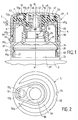
- FIG. 1 represents a dispensing assembly designated by 1.
- This assembly consists of a flexible plastic container 2 and a dispensing head generally designated by 3.
- the container 2 consists of a bottle proper (not shown) surmounted by a neck 21, disposed above a plane annular shoulder 22.
- the neck 21 consists of three successive coaxial parts: a first cylindrical part 23 carrying radial fins 27, a second part 24 having a generally frustoconical shape and forming at its junction with the first cylindrical part an annular projection 25 of diameter greater than that of the first cylindrical skirt, and a second cylindrical part 26 more small diameter.
- the head 3 consists of three elements: an outer cover 4 provided on its upper surface (in the position shown in FIG. 1), with a circular opening 41, the edge of which serves as a base for the closing device F; an intermediate piece of flexible material 5 carrying a flexible valve 51; and a reducer 6.
- the reducer 6 is fixed on the neck 21 of the bottle, the cover 4 is mounted to rotate freely on the reducer 6 and the piece of flexible material 5 is fixed in the cover 4 between said cover 4 and the reducer 6 .
- the reduction gear 6 comprises an external cylindrical skirt 61 divided into two parts 61 a and 61 b connected by a shoulder 61 c
- the lower part 61 a of the external skirt 61 has an external diameter equal to the external diameter of the shoulder 22 of the container 2 so as to form therewith a substantially continuous wall.
- the skirt 61 has an internal bead 62 which is placed by snapping under the projection 25 of the neck 21 of the bottle 2; it is also provided below the bead 62 with fins 63 which cooperate with the fins 27 of the cylindrical part 23 of the neck to prevent the reduction of the reduction gear 6 relative to the neck 21 of the container 2.
- the upper part 61 b of the skirt 61 carries an annular external flange 64 for fixing the cover 4 relative to the reducer 6, with free rotation of the cover 4 relative to the reducer 6.
- the skirt 61 carries, at the upper part of the part 61 b , a first flat annular flange 65 carrying annular beads 65 has turned outwards.
- the flange 65 is connected to a second planar annular flange 66 disposed in the vicinity of the upper edge of the neck 21 and of smaller diameter than the flange 65, the two flanges 65, 66 being connected to each other by a cylindrical-conical surface 67.
- a cylindrical skirt 68 facing the container 2 which has an external diameter equal, apart from the necessary clearance, to the internal diameter of the neck 21.
- a cylindrical skirt 69 with an opening 70.
- the cover 4 has a slightly curved upper surface 42, in which the opening 41 is formed, said opening being situated outside the axis X - X of the dispensing head 3.
- a cylindrical side skirt 43 directed towards the container; this skirt 43 extends to the level of the shoulder 61 c of the reducer 6.
- the lower edge of the skirt 43 carries, in radial relief, a position indicator 44.
- the edge of the shoulder 61 c carries markers making it possible to identify the rotation of the cover 4 relative to the reducer 6.
- On the internal face of the upper surface 42 is fixed an axial cylindrical skirt 45 having an external diameter equal, apart from the necessary clearance, to the internal diameter of the skirt 69 of the reducer 6.
- the axial cylindrical skirt 45 is provided with an opening 46 capable of coinciding, by rotation of the cover 4, with the opening 70 of the reducer 6. It can be seen that, in this embodiment, the valve device is formed by the two skirts 45 and 69 capable of rotating relative to each other and through the openings 46 and 70.
- On the inner face of the upper surface 42 of the cover 4 are arranged two ribs 47 and 48 intended to penetrate into grooves of corresponding shape pra ticked in room 5 as shown below.
- the side skirt 43 is provided with a radial rib 49 which penetrates into a notch 55 of the part 5 made of flexible material.
- the intermediate piece of flexible material 5 consists of a web having a generally annular shape centered on the axis X - X; this annular veil comprises a practically flat peripheral part 52 a and a frustoconical central part 52 b inclined towards the container.
- the part 5 is secured to the internal face of the upper surface 42 of the cover 4 by grooves 53 and 54 cooperating respectively with the ribs 47 and 48 of the cover 4; it is provided at its periphery with a notch 55 cooperating with the radial rib 49 of the cover 4.
- the part 5 rests by its lower face on the bosses 65 a of the reducer 6; it is, according to an advantageous embodiment, provided under the underside of the part 51 a , with a flexible radial blade (not shown) which can be positioned in a groove formed on the upper face of the reducer 6, between two wings radial parallels (not shown): this blade, when it comes into place in its groove, when the head 3 is turned, produces a slight click which allows the user to detect, acoustically, the moment when goes from the open position to the closed position.
- the part 5 has a cylindrical skirt 56 whose wall extends on either side of the web constituting the workpiece 5; above said veil, said wall is removed over approximately 150 ° to give rise to a notch 56 a .
- the notch 56 a opens in a chamber 57 delimited laterally by the rib 48 of the cover 4 and the skirt 69 of the reducer 6 and delimited at its lower part, by the veil of the piece of flexible material 5.
- the skirt 69 of the reducer 6 is engaged inside the skirt 56, which allows free rotation of the cover 4 relative to the reducer 6.
- the opening 46 is opposite the notch 56 a .
- the opening 70 of the reducer 6 can be, depending on the relative position of the cover 4 and the reducer 6, located opposite the opening 46 and can, therefore, put the chamber 57 in communication with the interior of the container.
- the valve 51 is fixed to the frustoconical part 51 b of the web of the part 5 and it is arranged in the chamber 57. It consists of a pad 51 a supported by a rod 5 b connected to the periphery of the pad 51 a .
- the patch 51 a has, in plan, a shape of a circle segment, the rod 51 b being connected according to the cord which joins the two ends of said circle segment; it is arranged in the opening 41 of the cover 4, so that, in the region of its circumference not connected to the rod 51b, it can cooperate in non-leaktight manner via its periphery with the fixed rigid base formed by the edge of the opening 41 and thus form the closing device F.
- the assembly operates as described below.
- the user wishes to dispense the product contained in the container 2, he rotates the cover 4 relative to the reducer 6 until the marks marked on the shoulder 61 c of the reducer 6 indicate to him that the openings 46 of the skirt 45 of the cover 4 and 70 of the skirt 69 of the reduction gear 6 are arranged opposite one another; the valve device is open and communication between the container 2 and the chamber 57 is then established.
- the user then presses on the container 2 made of flexible material.
- the product to be dispensed passes through the channel delimited by the neck 21, the skirts 68, 69 and 45, passes through the openings 46 and 70 and enters the chamber 57.
- the pellet 51 Under the pressure of the product, the pellet 51 has a valve 51 s' spreads outwards from the fixed base formed by the edge of the opening 41 of the cover 4: the distribution of the product begins.
- the wall of said container tends to return to its initial shape by elasticity and there is therefore a depression in the container 2 and in the chamber 57.
- the pellet 51 has a valve 51 is sucked into said chamber 57; the air enters the container 2.
- the pellet 51 a returns by elasticity to its rest position where it cooperates in a leaktight manner with the base formed by the edge of the opening 41 cover 4.
- the assembly 1 is again closed and ready for a new use. If the user wishes, for example before leaving on a trip, he can close the valve device by turning cover 4 in the opposite direction.
- FIGS 3 a and 3 b illustrate a variant 101 of an assembly according to the invention in which a cover 104 is movable in rotation relative to a reduction gear 106 and where the valve device is constituted by a needle system.
- the assembly 101 is constituted by a bottle 102 provided with a cylindrical neck 121 disposed on a shoulder 122 of the container 102.
- the neck 121 carries an external screw pitch 123 then a stop bead 124 and finally in the vicinity of the opening of the neck on a thinner area a snap strip 125.
- a dispensing head 103 is fixed on the neck 121: it comprises a cover 104, a piece 105 of flexible material and a reducer 106.
- the reducer 106 is constituted by a flat annular part 161 carrying on its external periphery a cylindrical skirt 162 facing the container. Said skirt 162 is provided on its internal wall with a groove 163 cooperating with the snap flange 125 of the neck 121 of the container 2.
- An internal skirt 164 is fixed on the internal edge of the annular part 161 and extends from side to side. on the other of said annular part 161. The skirt 164 has an external diameter equal, apart from the necessary clearance, to the internal diameter of the neck 121 and it is pressed into said neck 121, the planar annular part 161 resting on the upper edge of the neck 121.
- the upper part of the skirt 164 is extended by a frustoconical part 165 inclined towards the axis X - X of symmetry of the dispensing head 103; the frustoconical part 165 is provided with openings 166.
- the frustoconical part 165 is closed by a circular surface 167 connected to its part of smaller diameter by a cylindrical wall.
- the cover 104 comprises a flat upper surface 142 provided with an opening 141 and fixed by snap-fastening on a cylindrical external skirt 143 which extends in the direction of the shoulder 122 of the container 102.
- the internal wall of the skirt 143 comprises a thread 144 which cooperates with the screw pitch 123 of the neck 121.
- the skirt 143 carries a transverse wall 145 comprising a central circular opening 148.
- the transverse wall 145 comprises, around the opening 148, a frustoconical bearing 146 formed by the beveled edge of the wall 145.
- the frustoconical bearing 146 has dimensions complementary to the frustoconical portion 165.
- the frustoconical bearing 146 extends towards the container by a cylindrical skirt 147 , which has an internal diameter equal, apart from the necessary clearance, to the external diameter of the skirt 164 of the reducer 106.
- the piece 105 made of flexible material is disposed in the cover 104 between the upper surface 142 and the transverse wall 145.
- This piece 105 is hollowed out of a chamber 157 into which the opening 148 opens out of the transverse wall 145 of the cover and which is disposed under the opening 141 of the upper surface 142 of the cover.
- the part 105 comprises the valve 151.
- This valve is formed, first of all, by a part forming a rod 151 b which is formed by an extra thickness of the piece 105 compensating for the thickness of the upper surface 142 of the cover, the rod 151 b being in contact with the edge of the opening 141, and, secondly, by a pellet 151 a , the edge is in leaktight contact with the edge of the opening 141.
- the patch 151 a is capable of deviating, by elasticity, from the edge of the opening 141 forming a base as well towards the outside of the dispensing head 103 inwardly of the chamber 157 to form the closing device F.
- the device operates as described below.
- the user wishes to dispense the product contained in the container 102, he begins by opening the needle type security system formed by the frustoconical surface 165 of the reducer 106 and by the frustoconical surface 146.
- the cover 104 is driven in a linear translational movement upwards along the axis X - X; the opening 148 emerges from the circular surface 167 which formed a shutter and an annular channel is formed between the frustoconical surfaces 165 and 146 which places the interior of the neck 121 through the openings 166 and the opening 148 and the chamber 157.
- the rotation of the cover 104 is blocked by abutment against the bead 124.
- the product leaves the container via the neck 121, the conduit defined by the skirt 164, the openings 166, the annular space formed between the conical surfaces 165 and 146, at the opening 148 and the chamber 157.
- the pellet 151 a of the valve 151 diverges by elasticity from the edge of the opening 141 of the cover forming a base.
- the depression formed in the container 102 and the chamber 157 by the elastic return of the wall of the container causes an air intake.
- the pellet 151 a deviates by bending towards the inside of the chamber 157.
- the pellet 151 a returns to the rest position in contact. not waterproof with the edge of the opening 141 forming a base.
- Figures 4 and 5 show two variants 201, 301 of a dispensing assembly according to the invention in which the valve device of the dispensing head 203, 303 is of the needle type.
- the necks 221 and 321 of the container, reducing 206 and 306 respectively are identical to those (121 and 106) of the assembly shown in Figures 3 a and 3 b.
- the shape of the piece 205, 305 made of elastic material as well as the upper part of the cover 204, 304 are the only ones modified with respect to the embodiment of FIG. 3.
- the upper surface of the cover has been removed and the part 205 of elastic material is fixed by fitting on a transverse wall 245.
- the transverse wall 245 has a relief 246 forming at its upper part a unclosed curved line which crosses the part 205 of flexible material and thus defines in the part 205 a valve 251.
- the base thereof that is to say the part which is not not in contact with the relief 246 and is opposite to it, is thinned by a groove 252.
- the closing device F is therefore formed by the edge of the valve 251 which is in leaktight contact with the side wall of the relief 246.
- a chamber 257 is provided under the valve 251.
- the piece 305 of flexible plastic material is disposed inside the cover 304 between an upper surface 342 and a transverse wall 345.
- the opening 341 n is not provided on the upper surface 342, but on an inclined part 343 of the side wall.
- the valve 351 consists of a pellet, which, in the rest position, is inclined so as to be in the plane of the inclined wall 343; this pellet is a thinned part of the part 305 so as to obtain a flexible valve; room 357 is housed in a chamber 357 disposed behind the pellet which forms the valve.
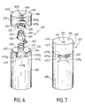
- Figures 6 and 7 show an assembly 401 according to the invention in which the valve system is formed by a vertical plug system constituted by two skirts provided with stackable openings, movable in rotation relative to each other. But in this embodiment, unlike that shown in Figure 1, the cover 404 is fixed relative to the container and the reduction gear 406 is movable in rotation.
- the assembly 401 comprises a container 402 of flexible plastic material provided with a neck 421 fixed on a shoulder 422.
- the side wall of the container and the shoulder are provided with a notch 423 projecting inside the container, the side walls 423 a are formed by radial planes, the bottom wall 423 b by a cylindrical sector and the lower wall by an annular segment 42 c .
- a groove 424 carrying a snap cord 425 At the junction between the shoulder 422 and the container 402 is provided a groove 424 carrying a snap cord 425.
- the neck 421 externally carries a snap bead 426 allowing the fixing of the reducer 406 of the dispensing head 403 in a movable manner. rotation.
- the reduction gear 406 has a first skirt 461 and a second skirt 463 separated by a shoulder.
- the skirt 461 has a diameter such that it can be fixed by snapping on the neck 421.
- the skirt 461 carries an operating button 462 fixed on a rod which is placed in the notch 423: the operating button 462 protrudes just the notch 423.
- the skirt 463 has a smaller diameter than the skirt 461 and it is provided on its free upper edge with a notch 464.
- the cover 404 has a circular upper surface 442 pierced with an off-center opening 441 At the periphery of the upper surface 442 is disposed a cylindrical outer skirt 443, the lower edge of which is fixed by snapping into the groove 424.
- the underside of the surface 442 carries an internal cylindrical skirt 444, the edge of which is provided with an opening 445.
- the skirt 444 is threaded inside the skirt 463.
- a piece 405 of flexible elastic material is fixed under the upper surface 442 of the cover 404; it comprises a skirt 452, which surrounds the skirt 463 of the reducer; the valve 451 is a wafer 451 is carried by the upper edge of the skirt 452, said wafer being connected to the skirt by a zone of small width comprising a rod 451 b.
- the disc of the valve 451 is placed, in the rest position, inside the opening 441 of the cover 404.
- the chamber provided under the valve 451, between the skirts 452 and 463, is in communication with the opening 464 of the reducer 406.
- the operating button 462 is acted between limit positions determined by the radial planes 423 a .
- the reducer 406 is thus made to rotate between an open position where the openings 464 and 445 coincide and a closed position where these openings no longer coincide.
- the operating member 462 can be replaced by a thumb wheel going around the reduction gear 406.
- the cover 404 and the bottle 402 have a generally oval shape.
- a notch is provided on the two sides of small curvature of the hood so that this wheel is maneuverable between the thumb and the index finger of the user.
- Figures 8 to 10 show a variant of the assembly according to the invention in which the valve of the closure system is constituted by an elastic nipple carrying a needle which is crushed under the pressure of the product, so that the needle releases by translation the base, and the valve device is a horizontal plug system.
- the distribution assembly is designated as a whole by 501; it consists of a flexible material container 502 shown partially in the drawing and of a dispensing head designated as a whole by 503.
- the head 503 consists of three elements: an outer cover 504 provided on its upper surface with a circular opening 541 serving as a base for the closing system F; an intermediate piece of elastic material 505; and a reducer 506.
- the reducer 506 is fixed to the bottle; the intermediate piece of flexible material 505 carries a valve 551 cooperating with the opening 541; the cover 504 forms a movable assembly in rotation about the vertical axis X-X of the neck, relative to the reduction gear 506.
- the bottle 502 is provided with a neck 521 of smaller diameter carrying an annular projection 525.
- the reduction gear 506 comprises an external skirt carrying on its internal wall a groove 562, in which the annular projection 525 of the neck.
- a system of fins (not shown), fixed on the neck and on the internal wall of the skirt 561, prevents any rotation of the reduction gear 506 relative to the neck 521.
- the skirt 561 carries at its upper part a flat annular collar 565, which is connected via a frustoconical surface 567 facing the container to an axial chimney 569 provided with an opening 570.
- Below the flange 565 is disposed a cylindrical axial sealing skirt 568, facing the container 502, which has an external diameter equal, apart from the necessary clearance, to the internal diameter of the neck 521.
- the cover 504 has a slightly curved upper surface 542, in which an opening 541 is formed, an opening situated outside the axis X - X of the dispensing head 503.
- a cylindrical skirt lateral 543 directed towards the container and fixed in rotation by a bead-groove system on the external wall of the skirt 561 of the reducer 506.
- a skirt 544 On the internal face of the surface 542 is formed a skirt 544 forming an annular projection having a diameter less than that of the skirt 543.
- a chamber 545 in the form of a dome is formed in the surface 542 around the opening 541, this chamber being tangent to the skirt 544.
- the internal face of the surface 542 also carries a projection 546 in the form of arc of a circle open towards chamber 545, this projection 546 surrounding the chimney 569 and having a diameter greater than that of said chimney 569.
- Said internal face also carries a ju eg axial cylindrical 547 having an external diameter equal, up to the necessary clearance, to the internal diameter of the chimney 569.
- an opening 548 capable of coinciding, by rotation of the cover 504 relative to the reducer 506, with the opening 570 of the chimney 569 for the distribution position.
- the intermediate piece 505 of flexible material has a generally planar annular surface 552 perpendicular to the axis X - X of the head 503.
- the valve 551 which has the shape of a dome carrying a needle 551 is capable of closing the opening 541 of the cover 504; the upper part of the needle 551 a and the edge of the opening 541 forms the closure system F.
- the planar annular surface 552 is bordered at its periphery by a skirt 553, which is inserted between the skirt 543 and the projection 544 of the cover 504.
- skirts 554 and 555 in the shape of an arc of a circle; the skirt 554 is constituted by a circular arc having an internal diameter equal, apart from the necessary clearance, to the external diameter of the chimney 569 and the two skirts 554 and 555 provide between them a space such that the skirt 546 of the cover 504 can s 'insert there.
- the open angle left by the various semi-circular skirts 554, 546 and 555 is such that the opening 570 of the chimney 569 is free for a position of the sub-assembly mobile 504-505 relative to the fixed sub-assembly 502-506, position which corresponds to the distribution.
- Under the planar annular surface 552 is disposed a projection in the form of a frustoconical cone which is placed between the frustoconical wall 567 and the chimney 569 of the reducer 506.
- the device 501 operates as follows: when the user wishes to dispense the product contained in the container 502, he rotates the integral assembly constituted by the cover 504 and the intermediate piece 505 relative to the reducer 506 until the opening 548 of the skirt 547 of the cover 504 coincides with the opening 570 of the chimney 569; in this position, the opening 570 is opposite the open angle provided in the concentric skirts 554, 546 and 555. The user then presses on the container 502 and the product contained in this container enters the chimney 569 and, after having passed through the openings 548 and 570, enters the chamber 545.
- the product exerts a pressure on the dome 551 which deforms and flattens towards the interior of the chamber 545 giving the needle 551 a a translational movement, which releases the opening 541 of the cover 504.
- the product can then exit.
- the product ceases to exert pressure on the dome 551 which returns to its initial shape, the needle 551 a returning by translation to close the opening 541.
- the assembly 501 is then closed again. If desired, the user can close the valve device by rotating the cover 504 in the opposite direction relative to the container 502.
- FIGS 11 to 15 show an embodiment of a dispensing device according to the invention in which the valve has the shape of a pellet and the valve device is horizontal plug.
- the dispensing device is designated as a whole by the reference 601; it consists of a flexible bottle 602 on the neck 621 from which is screwed a dispensing head generally designated by 603.
- the dispensing head 603 is formed by the assembly of three elements: a cover 604 having a circular opening 641 , a flexible intermediate piece 605 comprising the valve 651 cooperating with the edge of the opening 641 to form the closing system F and a reduction gear 606; the reduction gear 606 is fixed and the assembly constituted by the cover 604 and the intermediate piece 605 is movable in rotation relative to the reduction gear 606, about an axis horizontal perpendicular to the vertical longitudinal axis XX of the dispensing device.
- the reducer 606 consists of a cylindrical skirt 661 provided, on its internal face, with a screw pitch cooperating with a complementary screw pitch of the neck 621 of the bottle 602.
- a surface annular plane 662 On the upper edge of the skirt 661 is provided a surface annular plane 662; this surface 662 is provided, on the bottle side, with a sealing skirt 663 placed inside the neck 621
- an axial duct 664 On the other face of the surface 662 is disposed an axial duct 664 provided at its end furthest from the bottle d 'A cylindrical plug 665 whose axis is perpendicular to the longitudinal axis X - X of the dispensing device 601.
- This plug 665 is provided with a slot 666 diametrically opposite the conduit 664.
- the cover 604 is composed of two shells 642 and 643 assembled by fitting together; during the assembly of the two shells, two openings are arranged on the horizontal axis of the plug, openings in which are arranged pins 644 integral with the ends of the plug 665 and guiding the rotation of the sub-assembly (cover 604 / piece intermediate 605) elastic around the plug 665.
- the upper shell 643 has the opening 641. It has an internal projection 645, which serves as a support for the rod carrying the valve 651. Between the two shells 642 and 643 is formed a chamber 646.
- the flexible intermediate piece 605 carries the disc forming a valve 651 by means of a rod 652 which is in abutment against the projection 645 shell 643, it comprises a blade 653 which rests on the internal face of shell 642, at its end opposite to that carrying the valve 651, it is provided with an element in the form of a cylinder segment 654 having dimensions such that it can pivot around the plug 665.
- this element 654 is formed a slot 655 capable of coinciding by rotation with the slot 666 of the plug 665.
- the sub-assembly (cover 604 / intermediate piece 605) is arranged vertically.
- the dispensing head 603 can then be protected by a cover 607 (FIG. 15) fixed by snap-fastening on a bead 622 of the flexible bottle 602.
- the opening 666 is opposite the opening 655 and the bottle 602 is in communication with the chamber 646.
- the user then manually exerts pressure on the flexible bottle 602.
- the product contained in the bottle 602 then exits through the neck 621, crosses the conduit 664 and the openings or slots 666 and 655 to enter the chamber 646.
- the disc 651 of the valve moves towards the outside of the fixed base formed by the edge of the opening 641 of the cover 604: the distribution of the product begins.
- the wall of the latter tends to return to its initial shape by elasticity and a depression is formed in the container 602, and in the chamber 646; the pellet 651 is sucked into the chamber 646; the air enters the container and when the container 602 is returned to atmospheric pressure, the pellet 651 resiliently returns to its rest position, where it cooperates in a leaktight manner with the edge of the opening 641 of the cover 604. L the user can then, if he deems it necessary, close the valve device by rotating the dispensing head in a vertical position and protect the dispensing head with the cover 607.
Landscapes
- Engineering & Computer Science (AREA)
- Mechanical Engineering (AREA)
- Closures For Containers (AREA)
- Containers And Packaging Bodies Having A Special Means To Remove Contents (AREA)
Claims (16)
- Abgabevorrichtung (101, 201, 301, 401, 501, 601) für mindestens ein flüssiges oder cremeartiges Produkt, die einen Behälter (2, 102, 202, 302, 402, 502, 602) und einen Abgabekopf (3, 103, 203, 303, 403, 503, 603) umfaßt, wobei der Abgabekopf mindestens einen an seinem Ende verschlossenen Abgabekanal umfaßt, der mit der Umgebung über eine Schließvorrichtung (F) kommuniziert, die eine biegsame Klappe (51, 151, 251, 351, 451, 551, 651) umfaßt, die unter dem Druck des abzugebenden Produktes elastisch verformbar ist und in Ruhestellung nicht dicht mit einer steifen, festen Einfassung (41, 141, 241, 341, 441, 541, 641) zusammenwirkt,
dadurch gekennzeichnet, daß sich die Klappe (51, 151, 251, 351, 451, 551, 651) unter dem Druck des abzugebenden Produktes durch elastische Verformung von der Einfassung (41, 141, 241, 341, 441, 541, 641) entfernt und sich dann, wenn die Abgabe des Produktes beendet ist, in eine von der Ruhestellung abweichende Stellung begibt, die eine Luftansaugung erlaubt und die relativ zur steifen, festen Einfassung im Inneren des Abgabekopfes liegt. - Vorrichtung nach Anspruch 1, dadurch gekennzeichnet, daß sie stromaufwärts zur Verschlußvorrichtung (F) eine Ventilvorrichtung umfaßt, die es erlaubt, die Kommunikation zwischen Behälter und Verschlußvorrichtung zu unterbrechen.
- Vorrichtung nach einem der Ansprüche 1 oder 2, dadurch gekennzeichnet, daß die Klappe (51, 151, 251, 351, 451, 651) in Ruhestellung unmittelbar mit der steifen Einfassung (41, 141, 241, 341, 441) zusammenwirkt, wobei sich die Klappe unter dem Druck des abzugebenden Produktes von der Einfassung zur Außenseite des Abgabekopfes (3, 103, 203, 303, 403, 503) hin, und dann nach innen in eine Kammer (57, 157, 257, 357, 457, 646) bewegt, die dafür vorgesehen ist, die Luftansaugung zu ermöglichen, wenn die Abgabe beendet ist, und dann, wenn die Luftansaugung beendet ist, schließlich in ihre Ruhestellung zurückkehrt.
- Vorrichtung nach einem der Ansprüche 1 bis 3, dadurch gekennzeichnet, daß die Klappe (51, 451) die Form eines Plättchens (51a, 451a) aufweist, das von einem Schaft (51b, 451b) getragen wird.
- Vorrichtung nach Anspruch 4, dadurch gekennzeichnet, daß der Schaft (51b) am Umfang des Plättchens (51a) befestigt ist.
- Vorrichtung nach Anspruch 5, dadurch gekennzeichnet, daß das Plättchen (51a) in der Draufsicht die Form eines Kreisabschnittes aufweist, wobei der Schaft (51b) mit der Sehnenseite verbunden ist, die den Kreisabschnitt begrenzt.
- Vorrichtung nach einem der Ansprüche 1 bis 3, dadurch gekennzeichnet, daß die Klappe (151, 251, 351) von einem dünnen Plättchen gebildet ist, das zu einem Teil (105, 205, 305) aus biegsamem Material gehört und direkt mit dem Teil verbunden ist.
- Vorrichtung nach einem der Ansprüche 1 oder 2, dadurch gekennzeichnet, daß die Klappe von einer elastischen Kuppe (551) gebildet ist, die an ihrer Spitze einen mit der Einfassung (541) zusammenwirkenden Stift (551a) trägt, wobei sich die Kuppe unter dem Druck des abzugebenden Produktes derart staucht, daß der Stift die Einfassung (541) freigibt und in seine Ruhestellung, in der er mit der Einfassung zusammenwirkt, zurückkehrt, wenn die Abgabe beendet ist.
- Vorrichtung nach einem der Ansprüche 1 bis 8, dadurch gekennzeichnet, daß die steife Einfassung durch den Rand einer Öffnung (41, 141, 341, 441) gebildet ist, die in der Oberseite (42, 142, 342, 442) einer Kappe (4, 104, 304, 404) angeordnet ist, welche die Außenfläche des Abgabekopfes bildet.
- Vorrichtung nach einem der Ansprüche 1 bis 9, dadurch gekennzeichnet, daß die Klappe (51, 151, 351, 451) zu einem Teil (5, 105, 305, 405) gehört, das im Inneren des Abgabekopfes (3, 103, 303, 403) formschlüssig mit der Kappe (4, 104, 304, 404) verbunden ist.
- Vorrichtung nach Anspruch 9, dadurch gekennzeichnet, daß die Öffnung, deren Rand die Einfassung definiert, auf der Achse des Behälterhalses angeordnet ist.
- Vorrichtung nach Anspruch 9, dadurch gekennzeichnet, daß die Öffnung (41, 141, 241, 441), deren Rand die Einfassung definiert, relativ zur Achse des Behälterhalses außermittig ist.
- Vorrichtung nach einem der Ansprüche 1 bis 8, dadurch gekennzeichnet, daß die Einfassung von einem Teil gebildet ist, das eine Erhöhung (246) umfaßt, die eine offene Linie beschreibt, wobei die Klappe (251) zu einem Teil (205) aus biegsamem Material gehört, das zumindest teilweise die Außenfläche des Abgabekopfes (203) bildet, und mit dem Rand der Erhöhung (246) zusammenwirkt.
- Vorrichtung nach Anspruch 2, alleine oder in Kombination mit einem der Ansprüche 3 bis 13, dadurch gekennzeichnet, daß die Ventilvorrichtung durch ein System gebildet ist, das zwei konzentrische Schürzen (69, 45) umfaßt, welche die gleiche Achse wie der Hals (21) des Behälters (2) aufweisen, wobei jede Schürze mit einer Öffnung (70, 46) versehen ist, wobei die Öffnungen (70, 46) so angeordnet sind, daß man sie durch Verdrehung einer Schürze relativ zur anderen zur Deckung bringen kann.
- Vorrichtung nach Anspruch 2, alleine oder in Kombination mit einem der Ansprüche 3 bis 13, dadurch gekennzeichnet, daß die Ventilvorrichtung ein Gehäusesystem (665) ist, dessen Achse senkrecht zur Längsachse (X-X) der Vorrichtung ist.
- Vorrichtung nach Anspruch 3, alleine oder in Kombination mit einem der Ansprüche 3 bis 13, dadurch gekennzeichnet, daß die Ventilvorrichtung durch ein Stiftsystem gebildet ist, in welchem ein erstes Element, das eine Aussparung (146) umfaßt, und ein zweites Element, das einen formschlüssig in die Aussparung passenden Ansatz (165) umfaßt, relativ zueinander translatorisch so verschiebbar sind, daß sie in der Öffnungsstellung einen Kanal zwischen dem Ansatz und der Aussparung freilegen, wobei mindestens der Ansatz oder die Aussparung kegelstumpfartig sind.
Applications Claiming Priority (2)
| Application Number | Priority Date | Filing Date | Title |
|---|---|---|---|
| FR9004829A FR2660877B1 (fr) | 1990-04-13 | 1990-04-13 | Ensemble de distribution d'au moins un produit liquide ou sous forme de creme. |
| FR9004829 | 1990-04-13 |
Publications (2)
| Publication Number | Publication Date |
|---|---|
| EP0452196A1 EP0452196A1 (de) | 1991-10-16 |
| EP0452196B1 true EP0452196B1 (de) | 1994-07-27 |
Family
ID=9395785
Family Applications (1)
| Application Number | Title | Priority Date | Filing Date |
|---|---|---|---|
| EP91400917A Expired - Lifetime EP0452196B1 (de) | 1990-04-13 | 1991-04-04 | Abgabevorrichtung für wenigstens ein flüssiges oder cremeartiges Produkt |
Country Status (7)
| Country | Link |
|---|---|
| US (2) | US5161718A (de) |
| EP (1) | EP0452196B1 (de) |
| JP (2) | JP3297923B2 (de) |
| CA (1) | CA2040082C (de) |
| DE (1) | DE69103067T2 (de) |
| ES (1) | ES2057801T3 (de) |
| FR (1) | FR2660877B1 (de) |
Families Citing this family (55)
| Publication number | Priority date | Publication date | Assignee | Title |
|---|---|---|---|---|
| US5310094A (en) * | 1991-11-15 | 1994-05-10 | Jsp Partners, L.P. | Preservative free sterile fluid dispensing system |
| US5373972A (en) * | 1991-11-15 | 1994-12-20 | Jsp Partners, L.P. | Preservative-free sterile fluid dispensing system |
| FR2690674B1 (fr) * | 1992-04-30 | 1996-01-26 | Oreal | Distributeur de produit a poche deformable. |
| GB9213534D0 (en) * | 1992-06-25 | 1992-08-12 | Courtaulds Packaging Ltd | Closure for container |
| FR2711620B1 (fr) * | 1993-10-21 | 1995-12-22 | Oreal | Ensemble de distribution équipé d'un organe de fermeture unidirectionnel. |
| FR2711555B1 (fr) * | 1993-10-22 | 1996-01-26 | Oreal | Ensemble de distribution à chambre de compression à volume variable à membrane. |
| FR2715133B1 (fr) * | 1994-01-18 | 1996-03-08 | Oreal | Récipient à paroi souple déformable, du type flacon, poche ou tube, et procédé de fabrication d'un tel récipient. |
| DE4403082C1 (de) * | 1994-02-02 | 1995-04-20 | Henkel Kgaa | Verschluß für einen Behälter für fließfähige Produkte |
| FR2716866B1 (fr) * | 1994-03-04 | 1996-04-19 | Oreal | Dispositif de distribution pour récipient à col. |
| US5456374A (en) * | 1994-09-19 | 1995-10-10 | Beck; Matthew R. | Tamper evident container closure |
| US6112953A (en) * | 1994-10-20 | 2000-09-05 | L'oreal | Dispensing assembly equipped with a unidirectional closure member |
| FR2731992B1 (fr) * | 1995-03-21 | 1997-04-30 | Oreal | Distributeur de produit liquide ou pateux utilisable notamment en cosmetique |
| US5842618A (en) * | 1995-03-30 | 1998-12-01 | Colgate-Palmolive Company | Dispensing closure with controlled valve actuation |
| FR2737706B1 (fr) * | 1995-08-11 | 1997-10-10 | Janvier Ets | Dispositif de bouchage d'un recipient et de distribution du produit qu'il contient |
| FR2739079B1 (fr) * | 1995-09-25 | 1997-11-14 | Oreal | Dispositif de conditionnement et de distribution |
| FR2742128B1 (fr) | 1995-12-08 | 1998-01-16 | Oreal | Tete de distribution equipee d'un systeme de fermeture a reprise d'air |
| US5680969A (en) * | 1995-12-18 | 1997-10-28 | Aptargroup, Inc. | Closure with dispensing valve and separate releasable internal shipping seal |
| US5680965A (en) * | 1996-01-29 | 1997-10-28 | Beck; Matthew R. | Tamper evident container closure |
| BR9702273A (pt) * | 1996-05-24 | 2000-05-02 | Defi International | Cápsula distribuidora para recipiente |
| US5927567A (en) | 1996-11-12 | 1999-07-27 | Owens-Illinois Closure Inc. | Dispensing closure and method of making |
| US5971232A (en) * | 1998-06-03 | 1999-10-26 | Aptargroup, Inc. | Dispensing structure which has a pressure-openable valve retained with folding elements |
| FR2781133B1 (fr) * | 1998-07-15 | 2000-09-22 | Dior Christian Parfums | Dispositif d'ouverture et fermeture d'un flacon ou d'un tube relativement souple |
| CN1208223C (zh) | 1998-08-03 | 2005-06-29 | 沃瑞斯克生物系统公司 | 容器开关 |
| US6095382A (en) * | 1998-09-21 | 2000-08-01 | Aptargroup, Inc. | Container and closure with dispensing valve and separate releasable internal shipping seal |
| FR2783510B1 (fr) * | 1998-09-23 | 2000-12-15 | Sofab | Capsule de bouchage d'un recipient de produit liquide |
| WO2000024644A1 (de) * | 1998-10-22 | 2000-05-04 | Alpla Werke Alwin Lehner Gmbh & Co Kg | Spender mit selbstverschliessendem verschluss |
| US6006960A (en) * | 1998-10-28 | 1999-12-28 | Aptargroup, Inc. | Dispensing structure which has a lid with a pressure-openable valve |
| US5938086A (en) * | 1998-11-05 | 1999-08-17 | Aptargroup, Inc. | Container and closure with non-rising rotatable housing, dispensing valve, and separate releasable internal shipping seal |
| US6199297B1 (en) * | 1999-02-01 | 2001-03-13 | Integrated Biosystems, Inc. | Lyophilization apparatus and methods |
| US6290108B1 (en) | 2000-04-14 | 2001-09-18 | Seaquist Closures Foreign, Inc. | Dispensing system with an internal releasable shipping seal and an extended tip containing a pressure openable valve |
| US6334555B1 (en) | 2000-05-25 | 2002-01-01 | Seaquist Closures Foreign, Inc. | Fitment and resealable dispensing closure assembly for high-pressure sealing and bi-modal dispensing |
| US6446844B1 (en) | 2001-12-18 | 2002-09-10 | Seaquist Closures Foreign, Inc. | Closure with internal flow control for a pressure openable valve in an extendable/retractable nozzle |
| US7025232B2 (en) | 2002-06-03 | 2006-04-11 | John Green | Liquid-candy dispensing sprayer and container assembly |
| US6889876B2 (en) * | 2002-06-11 | 2005-05-10 | C&N Packaging, Inc. | Center dispenser cap assembly |
| NL1021536C1 (nl) * | 2002-09-26 | 2004-03-29 | Bound2B B V | Inrichting voor het houden van vloeistoffen, in het bijzonder dranken. |
| AT412152B (de) | 2003-01-16 | 2004-10-25 | Erich G Drazdansky | Trinkvorrichtung |
| US6986367B2 (en) * | 2003-11-20 | 2006-01-17 | Certainteed Corporation | Faced mineral fiber insulation board with integral glass fabric layer |
| US7025235B1 (en) * | 2004-10-01 | 2006-04-11 | Valley Design, Inc. | Fluid dispenser with adjustable size dispensing orifice |
| FR2900394B1 (fr) * | 2006-04-26 | 2008-06-27 | Plastohm Division Emballages S | Systeme de distribution anti-suintement d'un produit conditionne, et conditionnement le comportant |
| USD586215S1 (en) | 2007-05-04 | 2009-02-10 | Conopco Inc. | Part of an aerosol |
| USD581270S1 (en) | 2007-05-04 | 2008-11-25 | Conopco Inc. | Actuator |
| USD593412S1 (en) | 2007-05-04 | 2009-06-02 | Conopco, Inc. | Part of an aerosol |
| USD580776S1 (en) * | 2007-05-04 | 2008-11-18 | Conopco, Inc. | Aerosol dispenser |
| USD579342S1 (en) * | 2007-05-04 | 2008-10-28 | Conopco, Inc. | Aerosol dispenser |
| US8251263B2 (en) | 2008-03-24 | 2012-08-28 | Mary Kay Inc. | Container caps and systems |
| MX2011000976A (es) * | 2008-07-24 | 2011-07-29 | Mary Kay Inc | Tapas y sistemas para contenedor. |
| JP5651321B2 (ja) * | 2009-10-30 | 2015-01-07 | 株式会社吉野工業所 | 吐出器 |
| US8397957B2 (en) | 2010-01-06 | 2013-03-19 | Berry Plastics Corporation | Dispensing valve |
| US10039319B2 (en) * | 2014-06-20 | 2018-08-07 | Bashar Sawalha | In-line percolator style filter attachment device |
| DE102016212892C5 (de) * | 2016-07-14 | 2020-01-30 | F. Holzer Gmbh | Pumpkopf sowie Dosiervorrichtung |
| US11286103B2 (en) | 2018-12-21 | 2022-03-29 | Paul J. Lapeyrouse | Multiple component confectionery delivery product and method for delivery |
| USD942867S1 (en) | 2019-03-13 | 2022-02-08 | Ftgc, Llc | Multi-component confectionery dispenser |
| CN112918906B (zh) * | 2019-12-05 | 2024-09-27 | 邵晖 | 一种快速开启的容器 |
| US12162653B2 (en) | 2021-08-12 | 2024-12-10 | Avantor Fluid Handling, Llc | Cap with dual valve aseptic seals |
| CN118660850A (zh) * | 2022-03-07 | 2024-09-17 | 阿凡特流体处理有限责任公司 | 具有双阀无菌密封件的盖 |
Citations (1)
| Publication number | Priority date | Publication date | Assignee | Title |
|---|---|---|---|---|
| EP0111798A2 (de) * | 1982-12-21 | 1984-06-27 | Wella Aktiengesellschaft | Selbsttätiger Verschluss für flexible Behälter |
Family Cites Families (19)
| Publication number | Priority date | Publication date | Assignee | Title |
|---|---|---|---|---|
| US3128919A (en) * | 1964-04-14 | Liquid measuring and dispensing device | ||
| US3204836A (en) * | 1962-05-03 | 1965-09-07 | Park Plastics Co Inc | Dispenser |
| US3158183A (en) * | 1962-07-25 | 1964-11-24 | Parke Davis & Co | Push button dropper |
| US3297212A (en) * | 1965-01-21 | 1967-01-10 | Neuner Nikolaus | Bottle cap and closure |
| US3360169A (en) * | 1966-01-19 | 1967-12-26 | Lion Fat Oil Co Ltd | Container with an improved dispensing closure |
| FR1530565A (fr) * | 1967-05-16 | 1968-06-28 | Dispositif distributeur perfectionné muni d'un récipient extérieur à la fois flexible et élastique | |
| FR1540565A (fr) * | 1967-09-26 | 1968-09-27 | Beteiligungs & Patentverw Gmbh | Barre de remorquage, notamment pour avions |
| US3545682A (en) * | 1968-10-09 | 1970-12-08 | Walter C Beard | Dispensing device |
| US3651998A (en) * | 1970-09-23 | 1972-03-28 | Metallurg Exoproducts Corp | Nozzle for a pouring ladle |
| SE7607931L (sv) * | 1976-07-12 | 1978-01-13 | Kenova Ab | Forreglingsanordning for sjelvstengande forslutningar |
| US4179051A (en) * | 1977-08-01 | 1979-12-18 | Ryder International Corporation | One-piece check valve for use in a fluid dispenser |
| US4314658A (en) * | 1980-01-30 | 1982-02-09 | Laauwe Robert H | Viscous product dispensing squeeze bottle having a self-venting automatic shut-off valve |
| US4420101A (en) * | 1981-11-18 | 1983-12-13 | Diamond International Corp. | Squeeze bottle with self-venting dispensing closure |
| US4506809A (en) * | 1982-06-25 | 1985-03-26 | Calmar, Inc. | Dispensing fitment for squeeze bottles |
| US4699300A (en) * | 1985-10-25 | 1987-10-13 | Blake William S | Two piece dispensing closure with positive shutoff |
| US4739906A (en) * | 1986-07-14 | 1988-04-26 | Blairex Laboratories, Inc. | Storage bottle for contact lens cleaning solution having a self closing valve assembly |
| US4747518A (en) * | 1986-12-02 | 1988-05-31 | Laauwe Robert H | Squeeze bottle self-closing and venting dispensing valve |
| DK0442858T3 (da) * | 1990-02-16 | 1994-09-19 | Sterisol Ab | Ventil til portionsvis afgivelse af en væske |
| US5071017A (en) * | 1991-02-15 | 1991-12-10 | Stuli Iene | Closure cap construction with slitted flexible diaphragm |
-
1990
- 1990-04-13 FR FR9004829A patent/FR2660877B1/fr not_active Expired - Lifetime
-
1991
- 1991-04-04 EP EP91400917A patent/EP0452196B1/de not_active Expired - Lifetime
- 1991-04-04 DE DE69103067T patent/DE69103067T2/de not_active Expired - Fee Related
- 1991-04-04 ES ES91400917T patent/ES2057801T3/es not_active Expired - Lifetime
- 1991-04-09 CA CA002040082A patent/CA2040082C/fr not_active Expired - Fee Related
- 1991-04-11 US US07/683,824 patent/US5161718A/en not_active Expired - Lifetime
- 1991-04-12 JP JP22819991A patent/JP3297923B2/ja not_active Expired - Fee Related
-
1993
- 1993-09-17 US US08/130,147 patent/US5325999A/en not_active Expired - Lifetime
-
2000
- 2000-07-26 JP JP2000224794A patent/JP3395078B2/ja not_active Expired - Fee Related
Patent Citations (1)
| Publication number | Priority date | Publication date | Assignee | Title |
|---|---|---|---|---|
| EP0111798A2 (de) * | 1982-12-21 | 1984-06-27 | Wella Aktiengesellschaft | Selbsttätiger Verschluss für flexible Behälter |
Also Published As
| Publication number | Publication date |
|---|---|
| JP3395078B2 (ja) | 2003-04-07 |
| EP0452196A1 (de) | 1991-10-16 |
| JPH05138086A (ja) | 1993-06-01 |
| CA2040082C (fr) | 1999-12-21 |
| CA2040082A1 (fr) | 1991-10-14 |
| US5161718A (en) | 1992-11-10 |
| FR2660877B1 (fr) | 1992-07-31 |
| DE69103067T2 (de) | 1995-03-30 |
| US5325999A (en) | 1994-07-05 |
| JP2001058664A (ja) | 2001-03-06 |
| FR2660877A1 (fr) | 1991-10-18 |
| ES2057801T3 (es) | 1994-10-16 |
| DE69103067D1 (de) | 1994-09-01 |
| JP3297923B2 (ja) | 2002-07-02 |
Similar Documents
| Publication | Publication Date | Title |
|---|---|---|
| CA2040082C (fr) | Ensemble de distribution d'au moins un produit liquide ou sous forme de creme | |
| CA2021856C (fr) | Ensemble de distribution d'au moins un produit fluide, notamment cosmetique ou pharmaceutique | |
| CA2262135C (fr) | Ensemble de conditionnement et de distribution d'un produit liquide | |
| EP0538094B1 (de) | Metallbehälter, der entlang einer Schwächungslinie teilweise geöffnet werden kann | |
| BE1004397A3 (fr) | Dispositif permettant le conditionnement d'un produit et sa distribution par la manoeuvre d'un bouton-poussoir associe a un applicateur tubulaire. | |
| EP0564370B1 (de) | Verpackungsvorrichtung, insbesondere für kosmetische Produkte | |
| EP0780324B1 (de) | Ausgabekop für ein plässiges oder viskoses produkt, sowie mit diesem versehener spender | |
| EP0132189B1 (de) | Verschlusskapsel mit ausschiessbarer Ausgusstülle | |
| EP0670275A1 (de) | Dichtverschliessbare Abgabevorrichtung für einen Druck- oder Pumpbehälter | |
| CA2026831A1 (fr) | Dispositif de distribution comportant au moins un flacon a embout cassable | |
| EP0636549B1 (de) | Vorrichtung zur Abgabe eines flüssigen oder pastösen Produktes ohne Luftzutritt, mit einer deformierbaren Membran | |
| EP0329582B1 (de) | Spender für pastöse Produkte, versehen mit einem zur seitlichen Ausgabe dienenden axialen Betätigungskopf, und Verhüllungselement für seine Ausgabeöffnung | |
| EP1751023B1 (de) | Verteilvorrichtung für parfum | |
| EP0755880B1 (de) | Abgabevorrichtung für ein unter Druck stehendes Produkt und mit einer solchen Vorrichtung versehener Behälter | |
| CA2041711C (fr) | Dispositif d'actionnement d'une valve de distribution | |
| EP0559881B1 (de) | Verfahren zum Gewährleisten der Rotationsorientierung eines Verschlusses gegenüber einer mit einer Bezeichnung versehenen flexiblen Tube. | |
| EP2178415A2 (de) | Vorrichtung für ein kosmetikprodukt mit einem tank und einem applikator | |
| FR2632280A1 (fr) | Recipient pressurise permettant la distribution du produit qu'il contient dans des conditions de manoeuvre aisees | |
| EP0373989B1 (de) | Behälterverschlusskappe mit schwenkbarem Betätigungselement zum Abgeben des Behälterinhalts | |
| FR2814727A1 (fr) | Valve destinee a equiper un dispositif pour la distribution sous pression d'un produit, et dispositif ainsi equipe | |
| CA2260317C (fr) | Ensemble de distribution d'au moins un produit liquide ou sous forme de creme | |
| EP0780316B1 (de) | Manipulierbarer Behälter aus Kunststoff | |
| EP0739826B1 (de) | Verschlussvorrichtung mit einer seitlichen, axial ausziehbaren Oeffnung | |
| FR2635085A1 (fr) | Distributeur a embout inviolable | |
| FR2662424A1 (fr) | Ensemble de distribution d'un produit, comportant un embout de distribution sans reprise d'air. |
Legal Events
| Date | Code | Title | Description |
|---|---|---|---|
| PUAI | Public reference made under article 153(3) epc to a published international application that has entered the european phase |
Free format text: ORIGINAL CODE: 0009012 |
|
| 17P | Request for examination filed |
Effective date: 19910409 |
|
| AK | Designated contracting states |
Kind code of ref document: A1 Designated state(s): BE CH DE ES FR GB IT LI NL SE |
|
| 17Q | First examination report despatched |
Effective date: 19921001 |
|
| GRAA | (expected) grant |
Free format text: ORIGINAL CODE: 0009210 |
|
| AK | Designated contracting states |
Kind code of ref document: B1 Designated state(s): BE CH DE ES FR GB IT LI NL SE |
|
| PG25 | Lapsed in a contracting state [announced via postgrant information from national office to epo] |
Ref country code: NL Effective date: 19940727 |
|
| REF | Corresponds to: |
Ref document number: 69103067 Country of ref document: DE Date of ref document: 19940901 |
|
| ITF | It: translation for a ep patent filed | ||
| REG | Reference to a national code |
Ref country code: ES Ref legal event code: FG2A Ref document number: 2057801 Country of ref document: ES Kind code of ref document: T3 |
|
| PG25 | Lapsed in a contracting state [announced via postgrant information from national office to epo] |
Ref country code: SE Effective date: 19941027 |
|
| GBT | Gb: translation of ep patent filed (gb section 77(6)(a)/1977) |
Effective date: 19941013 |
|
| NLV1 | Nl: lapsed or annulled due to failure to fulfill the requirements of art. 29p and 29m of the patents act | ||
| PG25 | Lapsed in a contracting state [announced via postgrant information from national office to epo] |
Ref country code: BE Effective date: 19950430 |
|
| PLBE | No opposition filed within time limit |
Free format text: ORIGINAL CODE: 0009261 |
|
| STAA | Information on the status of an ep patent application or granted ep patent |
Free format text: STATUS: NO OPPOSITION FILED WITHIN TIME LIMIT |
|
| 26N | No opposition filed | ||
| BERE | Be: lapsed |
Owner name: L' OREAL Effective date: 19950430 |
|
| REG | Reference to a national code |
Ref country code: GB Ref legal event code: IF02 |
|
| PGFP | Annual fee paid to national office [announced via postgrant information from national office to epo] |
Ref country code: CH Payment date: 20070328 Year of fee payment: 17 |
|
| PGFP | Annual fee paid to national office [announced via postgrant information from national office to epo] |
Ref country code: DE Payment date: 20070329 Year of fee payment: 17 |
|
| PGFP | Annual fee paid to national office [announced via postgrant information from national office to epo] |
Ref country code: ES Payment date: 20070521 Year of fee payment: 17 |
|
| PGFP | Annual fee paid to national office [announced via postgrant information from national office to epo] |
Ref country code: GB Payment date: 20070404 Year of fee payment: 17 |
|
| PGFP | Annual fee paid to national office [announced via postgrant information from national office to epo] |
Ref country code: IT Payment date: 20070626 Year of fee payment: 17 |
|
| PGFP | Annual fee paid to national office [announced via postgrant information from national office to epo] |
Ref country code: FR Payment date: 20080312 Year of fee payment: 18 |
|
| REG | Reference to a national code |
Ref country code: CH Ref legal event code: PL |
|
| GBPC | Gb: european patent ceased through non-payment of renewal fee |
Effective date: 20080404 |
|
| PG25 | Lapsed in a contracting state [announced via postgrant information from national office to epo] |
Ref country code: LI Free format text: LAPSE BECAUSE OF NON-PAYMENT OF DUE FEES Effective date: 20080430 Ref country code: DE Free format text: LAPSE BECAUSE OF NON-PAYMENT OF DUE FEES Effective date: 20081101 Ref country code: CH Free format text: LAPSE BECAUSE OF NON-PAYMENT OF DUE FEES Effective date: 20080430 |
|
| REG | Reference to a national code |
Ref country code: ES Ref legal event code: FD2A Effective date: 20080405 |
|
| PG25 | Lapsed in a contracting state [announced via postgrant information from national office to epo] |
Ref country code: GB Free format text: LAPSE BECAUSE OF NON-PAYMENT OF DUE FEES Effective date: 20080404 |
|
| PG25 | Lapsed in a contracting state [announced via postgrant information from national office to epo] |
Ref country code: ES Free format text: LAPSE BECAUSE OF NON-PAYMENT OF DUE FEES Effective date: 20080405 |
|
| PG25 | Lapsed in a contracting state [announced via postgrant information from national office to epo] |
Ref country code: IT Free format text: LAPSE BECAUSE OF NON-PAYMENT OF DUE FEES Effective date: 20080404 |
|
| REG | Reference to a national code |
Ref country code: FR Ref legal event code: ST Effective date: 20091231 |
|
| PG25 | Lapsed in a contracting state [announced via postgrant information from national office to epo] |
Ref country code: FR Free format text: LAPSE BECAUSE OF NON-PAYMENT OF DUE FEES Effective date: 20091222 |