EP0452206B1 - Vorrichtung zum Tragen und Biegen von Glasscheiben und Anwendung zur Herstellung von gebogenen gehärteten Glasscheiben - Google Patents
Vorrichtung zum Tragen und Biegen von Glasscheiben und Anwendung zur Herstellung von gebogenen gehärteten Glasscheiben Download PDFInfo
- Publication number
- EP0452206B1 EP0452206B1 EP91400947A EP91400947A EP0452206B1 EP 0452206 B1 EP0452206 B1 EP 0452206B1 EP 91400947 A EP91400947 A EP 91400947A EP 91400947 A EP91400947 A EP 91400947A EP 0452206 B1 EP0452206 B1 EP 0452206B1
- Authority
- EP
- European Patent Office
- Prior art keywords
- glass
- bending
- stays
- glass sheet
- glass sheets
- Prior art date
- Legal status (The legal status is an assumption and is not a legal conclusion. Google has not performed a legal analysis and makes no representation as to the accuracy of the status listed.)
- Expired - Lifetime
Links
- 238000005452 bending Methods 0.000 title claims abstract description 36
- 239000011521 glass Substances 0.000 claims abstract description 94
- 238000011282 treatment Methods 0.000 claims abstract description 8
- 238000003825 pressing Methods 0.000 claims description 14
- 125000006850 spacer group Chemical group 0.000 claims description 10
- 239000004744 fabric Substances 0.000 claims description 8
- 238000004519 manufacturing process Methods 0.000 claims description 7
- 229910045601 alloy Inorganic materials 0.000 claims description 3
- 239000000956 alloy Substances 0.000 claims description 3
- 229910000831 Steel Inorganic materials 0.000 claims description 2
- 239000010425 asbestos Substances 0.000 claims description 2
- 229910052895 riebeckite Inorganic materials 0.000 claims description 2
- 239000010935 stainless steel Substances 0.000 claims description 2
- 229910001220 stainless steel Inorganic materials 0.000 claims description 2
- 239000010959 steel Substances 0.000 claims description 2
- 239000011214 refractory ceramic Substances 0.000 claims 1
- 239000005341 toughened glass Substances 0.000 claims 1
- 238000005496 tempering Methods 0.000 abstract description 9
- 238000000034 method Methods 0.000 description 11
- 230000008569 process Effects 0.000 description 8
- 238000010791 quenching Methods 0.000 description 8
- 238000009434 installation Methods 0.000 description 7
- 230000003287 optical effect Effects 0.000 description 5
- 230000000171 quenching effect Effects 0.000 description 5
- VYPSYNLAJGMNEJ-UHFFFAOYSA-N Silicium dioxide Chemical compound O=[Si]=O VYPSYNLAJGMNEJ-UHFFFAOYSA-N 0.000 description 4
- 230000007547 defect Effects 0.000 description 4
- 238000007664 blowing Methods 0.000 description 3
- 238000001816 cooling Methods 0.000 description 3
- 239000000835 fiber Substances 0.000 description 3
- 238000010438 heat treatment Methods 0.000 description 3
- 229920000914 Metallic fiber Polymers 0.000 description 2
- 230000008901 benefit Effects 0.000 description 2
- 238000006243 chemical reaction Methods 0.000 description 2
- 238000010586 diagram Methods 0.000 description 2
- 230000000717 retained effect Effects 0.000 description 2
- 238000007493 shaping process Methods 0.000 description 2
- 239000000377 silicon dioxide Substances 0.000 description 2
- 230000032258 transport Effects 0.000 description 2
- 229910000838 Al alloy Inorganic materials 0.000 description 1
- 230000004308 accommodation Effects 0.000 description 1
- 230000009471 action Effects 0.000 description 1
- 230000015572 biosynthetic process Effects 0.000 description 1
- 230000000903 blocking effect Effects 0.000 description 1
- 238000000071 blow moulding Methods 0.000 description 1
- 230000015556 catabolic process Effects 0.000 description 1
- 239000000919 ceramic Substances 0.000 description 1
- 230000008859 change Effects 0.000 description 1
- 239000011248 coating agent Substances 0.000 description 1
- 238000000576 coating method Methods 0.000 description 1
- 230000000295 complement effect Effects 0.000 description 1
- 239000000112 cooling gas Substances 0.000 description 1
- 238000005520 cutting process Methods 0.000 description 1
- 238000006731 degradation reaction Methods 0.000 description 1
- 238000011161 development Methods 0.000 description 1
- 230000000694 effects Effects 0.000 description 1
- 230000002349 favourable effect Effects 0.000 description 1
- 238000007667 floating Methods 0.000 description 1
- 235000013305 food Nutrition 0.000 description 1
- 238000013467 fragmentation Methods 0.000 description 1
- 238000006062 fragmentation reaction Methods 0.000 description 1
- 229910001026 inconel Inorganic materials 0.000 description 1
- 229910003437 indium oxide Inorganic materials 0.000 description 1
- PJXISJQVUVHSOJ-UHFFFAOYSA-N indium(iii) oxide Chemical compound [O-2].[O-2].[O-2].[In+3].[In+3] PJXISJQVUVHSOJ-UHFFFAOYSA-N 0.000 description 1
- 239000011229 interlayer Substances 0.000 description 1
- 229910000953 kanthal Inorganic materials 0.000 description 1
- 239000010410 layer Substances 0.000 description 1
- 230000004048 modification Effects 0.000 description 1
- 238000012986 modification Methods 0.000 description 1
- 229910000623 nickel–chromium alloy Inorganic materials 0.000 description 1
- 238000004663 powder metallurgy Methods 0.000 description 1
- 238000003303 reheating Methods 0.000 description 1
- 230000003014 reinforcing effect Effects 0.000 description 1
- 239000007779 soft material Substances 0.000 description 1
- 239000007787 solid Substances 0.000 description 1
- 239000000725 suspension Substances 0.000 description 1
- 238000012360 testing method Methods 0.000 description 1
- XOLBLPGZBRYERU-UHFFFAOYSA-N tin dioxide Chemical compound O=[Sn]=O XOLBLPGZBRYERU-UHFFFAOYSA-N 0.000 description 1
- 229910001887 tin oxide Inorganic materials 0.000 description 1
- 238000013519 translation Methods 0.000 description 1
Images
Classifications
-
- C—CHEMISTRY; METALLURGY
- C03—GLASS; MINERAL OR SLAG WOOL
- C03B—MANUFACTURE, SHAPING, OR SUPPLEMENTARY PROCESSES
- C03B23/00—Re-forming shaped glass
- C03B23/02—Re-forming glass sheets
- C03B23/023—Re-forming glass sheets by bending
- C03B23/03—Re-forming glass sheets by bending by press-bending between shaping moulds
- C03B23/031—Re-forming glass sheets by bending by press-bending between shaping moulds the glass sheets being in a vertical position
- C03B23/0315—Re-forming glass sheets by bending by press-bending between shaping moulds the glass sheets being in a vertical position and supported on the lower edge
-
- C—CHEMISTRY; METALLURGY
- C03—GLASS; MINERAL OR SLAG WOOL
- C03B—MANUFACTURE, SHAPING, OR SUPPLEMENTARY PROCESSES
- C03B35/00—Transporting of glass products during their manufacture, e.g. hot glass lenses, prisms
- C03B35/14—Transporting hot glass sheets or ribbons, e.g. by heat-resistant conveyor belts or bands
- C03B35/20—Transporting hot glass sheets or ribbons, e.g. by heat-resistant conveyor belts or bands by gripping tongs or supporting frames
- C03B35/202—Transporting hot glass sheets or ribbons, e.g. by heat-resistant conveyor belts or bands by gripping tongs or supporting frames by supporting frames
- C03B35/205—Transporting hot glass sheets or ribbons, e.g. by heat-resistant conveyor belts or bands by gripping tongs or supporting frames by supporting frames the glass sheets being in a vertical position
Definitions
- the invention relates to the support of glass sheets in a vertical or substantially vertical position during various treatments to which the glass sheets are subjected with a view to bending and / or tempering such as in particular reheating, bending for example by pressing, thermal quenching and transport between the different treatment stations.
- the invention also relates to a pressing bending device cooperating with a support device according to the invention. It applies in particular to the production of domed-toughened glazing of large dimensions having a very large curvature.
- the quality criteria most often required today are strict compliance with the prescribed curve, a degree of toughening corresponding to the desired increase in mechanical strength in order to also ensure fragmentation complies with safety standards, optical quality excluding any moiré effect and finally a total absence of any imprint left by the tools used during the various treatments and in particular an absence of gripper marks which in the treatments performed vertically support the glazing.
- European patent EP-B-126 687 proposes a frame whose holding means applying to the upper edge of the glass sheet are mounted freely in the vertical direction, by means of lateral guidance. These holding means, for example of the piston type, can thus accompany the glass sheet and continue to retain it even when it begins to collapse. Furthermore, these holding means can be coupled with clamps whose jaws only close again if the glass sheet escapes from the piston, which makes it possible to catch up said sheet, to prevent it from falling and breaking, to remove it from the oven and not to clutter it with broken glass.
- the frame according to EP-B-126 687 gives good results with small panes, that is to say more precisely with panes whose height is less than 600 mm. Beyond such a height, the subsidence during heating is too great and the jaws intervene almost systematically to grip the glass sheets, which certainly allows them to be removed from the bending-tempering installation, but not avoid pinch marks.
- the desired shape Even if few glazings actually have all their dimensions greater than 600 mm, it is not uncommon for the desired shape to impose a disposition of the glazing in the frame such that its height is confused with its largest dimension which is frequently greater than 1000 mm.
- the object of the present invention is to provide a new support for glass sheets in a vertical or substantially vertical position, capable of holding glass sheets during various treatments related to bending and / or tempering operations, even if the height of the glass sheets is greater than 600 mm and this, without generating pinch marks or optical defects due to too strong disruption of heating and thermal quenching operations.
- a support device for glass sheets in a vertical or substantially vertical position serving to hold them during various treatments related to bending and / or tempering operations, characterized in that it is consisting of one or more crosspieces, on which the lower edge of the glass sheet rests, each crosspiece being suspended from a lifting beam by one or more pairs of shrouds running along the two opposite faces of the glass sheet.
- the device according to the invention does not necessarily include means acting on the upper edge of the glass sheet which is simply placed on its lower edge and is retained laterally by the shrouds, if it deviates from its vertical equilibrium position or curls when it warms up.
- shrouds which encage the glass sheet, and whatever its height may be, any risk of falling of the glass sheet when it is reheated in the oven and all subsequent operations, in particular of tempering, is eliminated, without however hampering said quenching process, the shrouds being sufficiently thin and distant from the glass sheet so as not to disturb the intense cooling by blowing cold air.
- the shrouds are most often sufficient to retain the pieces of glass and prevent them from are dispersed throughout the installation. Furthermore, the fact that the amplitude of the movements of the glass sheet in this kind of cage is extremely low - and that the support device is more particularly intended for glazing whose height is large and generally greater than 600 mm, the horizontal reaction exerted by the shrouds is of very low intensity, which limits the marking phenomena.
- spacers are for example flexible pads which do not mark the hot glass; according to a particularly preferred embodiment of the invention, the spacers are constituted by sleeves made of a fabric of heat-resistant fabric, for example of asbestos-based fabric or preferably a felt of metallic fibers, strung on the shrouds.
- the number and location of the spacers can be easily determined after one or two tests which determine the location of any faults; in practice, about one sleeve is used every 20 centimeters, taking particular care to have it close to the edges of the glazing.
- similar pads made for example of a silica fiber fabric are also used as spacers between the crosspieces and the lower edge of the glass sheet.
- a second advantage of using these spacers is that they make it possible to tolerate the reaction forces of the slightly larger shrouds and therefore to reduce the number of these shrouds, which all the more limits the problems due to possible differences in expansion between the different shrouds.
- the shrouds are not necessarily well tensioned when the support device is empty, the weight of the glass sheets largely sufficient to exert the tension required to prevent the shrouds from rubbing permanently against the glass.
- the support device according to the invention can be used simply for the production of toughened flat glazing, without bending step, or also for obtaining curved glazing by means of simple pressing frames open at their center.
- the best advantage is taken of such a support device if it is used for the implementation of a bending process by pressing by means of solid shapes, possibly constituted by elements pivoting around their axes d 'assembly.
- the invention proposes a modification of the pressing forms, in this case the digging of the bearing surfaces on the glass sheet in order to define flat areas in which the shrouds of the support device will be able to be housed during closing the press, this of course to prevent the shrouds from being pressed against the glass sheet which would inevitably mark it.
- the flats are largely oversized, in width and in depth.
- this oversizing does not harm the optical quality of the glazing, whereas on the other hand, it increases the tolerances with regard to the positioning deviations of the shrouds or in other words makes it possible to accept, possibly, a greater expansion of shrouds and / or a slight error as to the suspension points of the shrouds on the spreaders.
- the invention is particularly applicable to the production of display cases, in particular for food products or jewelry items; in this case the glazing to be produced generally comprises two flat parts - and having to be strictly free from flatness defects taking into account the envisaged application - which are separated by a cylindrical part with very small radius of curvature.
- Such articles are advantageously produced using a bending press, the female form of which comprises a pivoting wing which folds the corresponding part of the glazing onto the male form.
- a support device comprising two crosspieces is advantageously used, each crosspiece being suspended from a lifting beam, preferably by at most two pairs of guy lines and advantageously by a single pair of guy lines and supporting one of the two parts of the glazing, the spreader corresponding to the folded part being advantageously capable of pivoting to follow the movements of the glass sheet.
- the invention also relates to the applications according to claims 14 and 15.
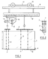
- FIG. 1 is a schematic view of a support device according to a first embodiment of the invention.
- the glass sheet 1 here rectangular, and having a height h of for example 1000 mm and a thickness of approximately 6 mm, is maintained in a vertical or substantially vertical position by the combined action of crosspieces 2 and 3 and guy wires 4
- the crosspieces 2 and 3 are suspended from the shrouds 4 which pass on each side of the glass sheet 1, forming a sort of cage.
- the upper end of the shrouds 4 is attached to swings 5.
- the shrouds 4 must be able to support the weight of the glass sheet and withstand the temperatures of the oven and the bending operations.
- wires 3 to 4 mm in diameter can be used, made of refractory steel, for example of the stainless steel, ferchrome-aluminum alloy or nickel-chromium alloy. Very good results have also been obtained with an alloy that is not very sensitive to hot creep, for example an alloy of the APM type supplied by the company Kanthal under Swedish law and produced by Powder Metallurgy.
- the shrouds 4 are kept under tension by the weight of the glass sheet.
- the shrouds 4 are for example fixed by screws 6 to a fastener 7 provided with forks 8 which define a gap d between the glass sheet 1 and the shrouds 4.
- This gap is advantageously chosen to be of the order of 2 mm.
- This difference is also ensured by a series of spacers 9 distributed over the entire length of the shrouds. These spacers are constituted by pads made of a fairly soft material, to better absorb the forces, not marking the glass and capable of withstanding high temperature and in particular at a temperature of the order of 650 ° C.
- sleeves made of a metallic fiber felt based on INCONEL, threaded on the shrouds 4 gives all satisfaction and moreover the sleeving system allows to modify in a simple way the position of the pads 9 as a function of the location of any faults.
- a pad 9 is enough every 15-20 cm, with a pad systematically near the edges of the glass sheet 1.
- the same felt or preferably a white felt made of silica fibers is optionally used as an interlayer between the crosspieces 2, 3 and the lower edge of the glass sheet. It should be noted that these pads 9 also play a role during thermal quenching by blowing cold air, because they allow good circulation of the cooling gas. You can also use fully sheathed wires using a ceramic fabric.
- each cross member can receive only one pair of shrouds and be very short.
- the loading operation of the glass sheet 1 is simplified if the balance is obtained fairly quickly, so that even in this case, it may be preferable to use sleepers at least 10 cm long. .
- one of the cross members is extended by a bar 10 provided with a heel 11 on which a lateral edge rests.
- the swings 5 are connected to a lifter 12 constituted by a beam provided with a series of holes constituting as many attachment points.
- the right swing is hung directly on this lifter 12.
- the left swing - which corresponds to the part of the glazing to be folded - is hung on a rack 13.
- This rack 13 is fixed to a support 14 hooked to the spreader 12.
- a hinge 15 makes it possible to rotate the rack 13 in a horizontal plane, a stop rod 16 preventing rotation from one side.
- the lifter 12 is itself carried by a carriage 17 whose wheels 18 are guided by a rail 19 which transports the glass sheet 1 held by its support device in the oven and the other bending and / or tempering installations.
- a bending-quenching installation typically comprising a lateral installation for loading glass sheets, a pit oven above from which the bending tools are arranged and at a third level, above the bending tools, the quench blow molding boxes.
- FIG. 1 relates only to one of the possible embodiments of the support device according to the invention and a series of other variations can be made, including in particular the method of attachment to the main lifting beam, being understood by those skilled in the art, that the glass is never retained by more than one fixed point on the lifter and that the other points are floating.
- the use of the swiveling lifting beam is of course only required if the glass sheet has to undergo a significant bending. The most significant change concerns the number of sleepers and guy lines.
- this number is fixed by the number of parts of the glazing, or in other words, a crosspiece for a flat or very slightly curved glazing, two crosspieces for a fold line (in the case of stove covers or display cases ) and three crosspieces for two fold lines (U-shaped glazing).
- Each crosspiece advantageously corresponds to at most two pairs of shrouds and if possible a single pair of shrouds - bearing in mind however that it is preferable to provide at least two pairs of shrouds per glazing.
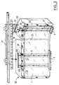
- FIG. 3 is an illustration of a more particularly advantageous use of the support frame shown diagrammatically in FIG. 1.
- the glass sheet 1 is shown being shaped using a bending press made up of two complementary forms of bending, the male form not having been represented for the sake of clarity.
- the female form 20 has two elements 21 and 22.
- the main element 21 has a shaping surface (that is to say a bearing surface on the glass sheet) coated with a fabric or felt of refractory fibers which also covers the surface of the element 22 and of the male counter-form, the elements 21 and 22 constituting the female form can be flat or curved according to a generally cylindrical curvature, depending on the type of glazing produced.
- the two elements 21 and 22 are articulated one on the other about a pivot axis 23 positioned so that the pivoting element 22 does not rub on the glass during folding.
- Means, not shown here, are provided for opening and closing the press and for pivoting the element 22.
- the glass sheet l is supported by the crosspieces 2 and 3 suspended from the shrouds 4.
- the surface of the elements 21 and 22 is hollowed out by flats 24 and 25.
- these are very oversized and for example have a width equal to more than ten times the diameter of the shrouds and a depth at least equal to twice this diameter and preferably three times this diameter.
- the bending operation takes place as follows: as soon as the glass sheet 1 previously warmed to the appropriate temperature is correctly positioned between the bending shapes, the male bending shape and the female bending shape are brought together, so let the main element come and apply the glass against the male element. Just before carrying out this pressing, we can observe that a glass sheet of more than 600 mm in height (and in a specific case of 1200 mm in height for 6 mm of thickness) is curled, but for as much perfectly maintained by the support device. During pressing the shrouds are stored in the flats 25.
- the element 22 is pivoted, which gradually folds down the wing of the glass sheet, starting with its part located near the pivot axis and ending with the edge of the glass sheet.
- a handlebar 26 integral with the element 22 pushes the rack 13 articulated, so that the glass is not cantilevered.
- the shrouds 4 ′ to which the cross member 3 is suspended also find a place in flats 25 provided for this purpose.
- the press After pressing is complete, the press is opened and the glass sheet is placed between quench blowing boxes. It appeared that the shrouds of the support device according to the invention in no way interfere with the cooling process and that, on the contrary, the breakage rates are rather lower than they are with support devices according to the art, the clamps tend to generate defects in the glazing, defects which are sensitive to hardening.
- This process notably made it possible to produce curved display cases without any mark of clips constituted by two flat parts, respectively 167 and 681 mm in length, separated by a fold forming an angle of 56 ° and having a radius of curvature of 114 mm, the hinge axis being parallel to the height of the glazing. Curve tolerances of less than + 2.5 mm have been observed for heights ranging from 620 mm to 1245 mm.
- the flats dug in the pressing shapes are preferably very wide to provide accommodation for the shrouds. Nevertheless, optical deformations can appear in some cases - in particular when the bending proceeds more by stamping than by bending. It is therefore preferable to limit the width of the flats to around 10-15 mm and guiding the shrouds by wire centralizers, for example V 27 mounted on the female part of the press. These centralizers are also used for the production of glazing comprising two folds which may then require the use of two articulated racks fixed to the lifter.
- the correct balance of the hitch can only be maintained by removing the central anchor point, which generates during folding a slight lateral translation of the top of the shrouds relative to the glass, which makes it difficult to correctly house the shrouds, difficulty raised by the use of centering.
- the method according to the invention allows not only the removal of any brand of pliers but also better conformity to the curve due to the absence of slippage at the pliers and the absence of elongation of the glass.
Landscapes
- Chemical & Material Sciences (AREA)
- Engineering & Computer Science (AREA)
- Materials Engineering (AREA)
- Organic Chemistry (AREA)
- Re-Forming, After-Treatment, Cutting And Transporting Of Glass Products (AREA)
- Laminated Bodies (AREA)
- Joining Of Glass To Other Materials (AREA)
- Glass Compositions (AREA)
- Filling Or Discharging Of Gas Storage Vessels (AREA)
Claims (16)
- Vorrichtung für das Halten von Glasscheiben (1) in senkrechter oder im wesentlichen senkrechter Position, welche zu deren Halten während der verschiedenen Behandlungen dient, die mit den Arbeitsgängen des Biegens und/oder Vorspannens verbunden sind, dadurch gekennzeichnet, daß sie aus einem oder mehreren Traversen (2, 3) gebildet ist, auf denen der untere Rand der Glasscheibe (1) ruht, wobei jede Traverse über ein oder mehrere Paare von Halteseilen (4), die über die beiden einander gegenüberliegenden Seiten der Glasscheiben laufen, an einer Tragschiene (12) hängt.
- Vorrichtung für das Halten von Glasscheiben nach Anspruch 1, dadurch gekennzeichnet, daß zwischen den Traversen (2, 3) und die Glasscheibe nachgiebige Auflagen (9) eingelegt sind.
- Vorrichtung für das Halten von Glasscheiben nach Anspruch 1 oder 2, dadurch gekennzeichnet, daß die Halteseile (4) durch Abstandshalter (9) von den Flächen der Glasscheibe entfernt gehalten werden.
- Vorrichtung für das Halten von Glasscheiben nach Anspruch 3, dadurch gekennzeichnet, daß die Abstandshalter (9) aus Hüllen bestehen, die aus einem hitzebeständigen Gewebe oder Filz hergestellt sind.
- Vorrichtung für das Halten von Glasscheiben nach Anspruch 4, dadurch gekennzeichnet, daß das hitzebeständige Gewebe Asbest oder feuerfeste Keramikfasern zur Grundlage hat.
- Vorrichtung für das Halten von Glasscheiben nach einem der vorhergehenden Ansprüche, dadurch gekennzeichnet, daß die Halteseile (4) durch das Gewicht der Glasscheibe (1) gespannt sind.
- Vorrichtung für das Halten von Glasscheiben nach einem der vorhergehenden Ansprüche, dadurch gekennzeichnet, daß die Halteseile (4) Drähte aus feuerfestem Stahl, insbesondere rostfreiem Stahl, oder aus einer Chrom-Nickel-Legierung sind.
- Vorrichtung für das Halten von Glasscheiben nach einem der vorhergehenden Ansprüche, dadurch gekennzeichnet, daß sie wenigstens einen gelenkigen Tragbalken (13) enthält.
- Vorrichtung für das Biegen von Glasscheiben, in der die Glasscheibe (1) von einer Haltevorrichtung nach einem der Ansprüche 1 bis 8 gehalten wird und welche aus einer senkrechten Biegepresse besteht, deren Formen Auflageflächen, die mit Vertiefungen (25, 26) versehen sind, welche die Halteseile (4) aufnehmen, auf der Glasscheibe besitzen.
- Vorrichtung für das Biegen von Glasscheiben nach Anspruch 9, dadurch gekennzeichnet, daß die Vertiefungen (25, 26) eine Breite aufweisen, die wenigstens das Fünffache und vorzugsweise wenigstens das Zehnfache des Durchmessers der Halteseile (4) beträgt.
- Vorrichtung für das Biegen von Glasscheiben nach Anspruch 10, dadurch gekennzeichnet, daß die Vertiefungen (25, 26) eine Tiefe aufweisen, die wenigstens das Doppelte und vorzugsweise wenigstens das Dreifache des Durchmessers der Halteseile (4) beträgt.
- Vorrichtung für das Biegen von Glasscheiben nach Anspruch 9, in welcher die Glasscheibe (1) von einer Haltevorrichtung nach Anspruch 8 gehalten wird, die zwei Traversen (2, 3) umfaßt, welche an höchstens vier Paaren von Halteseilen (4, 4') und vorzugsweise an zwei Halteseilpaaren (jeweils ein Paar pro Querbalken) aufgehängt sind, dadurch gekennzeichnet, daß die Matrizenbiegeform (20) zwei bezüglich einander schwenkbare Elemente enthält, wobei das erste Element (21) den Hauptteil der Glasscheibe anpreßt und anschließend das zweite Element (22) den Seitenteil auf dem Patrizenbereich umbiegt, und daß jeder Teil der Glasscheibe mit einer Traverse (2, 3) in Berührung steht, wobei der an einem schwenkbaren Tragbalken aufgehängte Querbalken (3) für den Seitenteil vorgesehen ist.
- Vorrichtung für das Biegen nach einem der Ansprüche 9 bis 12, dadurch gekennzeichnet, daß Zentriereinrichtungen (27) auf den Pressen befestigt und zur Führung der Halteseile (4) bestimmt sind.
- Verwendung der Vorrichtung nach einem der Ansprüche 9 bis 13 zum Biegen von Glasscheiben, die über 600 mm hoch sind.
- Verwendung der Vorrichtung nach einem der Ansprüche 9 bis 13 zur Herstellung von Erzeugnissen aus vorgespanntem Glas, das frei von Klemmenabdrücken ist und wenigstens eine zylindrische Fläche enthält, deren Radius kleiner als 150 mm ist.
- Verwendung nach Anspruch 15, dadurch gekennzeichnet, daß die zylindrische Fläche von zwei ebenen Flächen umgeben ist.
Applications Claiming Priority (2)
| Application Number | Priority Date | Filing Date | Title |
|---|---|---|---|
| FR9004806A FR2660920B1 (fr) | 1990-04-13 | 1990-04-13 | Dispositif et support et de bombage de feuilles de verre et application a la production vitrages bombes-trempes. |
| FR9004806 | 1990-04-13 |
Publications (2)
| Publication Number | Publication Date |
|---|---|
| EP0452206A1 EP0452206A1 (de) | 1991-10-16 |
| EP0452206B1 true EP0452206B1 (de) | 1994-10-12 |
Family
ID=9395771
Family Applications (1)
| Application Number | Title | Priority Date | Filing Date |
|---|---|---|---|
| EP91400947A Expired - Lifetime EP0452206B1 (de) | 1990-04-13 | 1991-04-09 | Vorrichtung zum Tragen und Biegen von Glasscheiben und Anwendung zur Herstellung von gebogenen gehärteten Glasscheiben |
Country Status (9)
| Country | Link |
|---|---|
| US (1) | US5292357A (de) |
| EP (1) | EP0452206B1 (de) |
| JP (1) | JP3193396B2 (de) |
| AT (1) | ATE112758T1 (de) |
| CA (1) | CA2039957C (de) |
| DE (1) | DE69104531T2 (de) |
| DK (1) | DK0452206T3 (de) |
| ES (1) | ES2064935T3 (de) |
| FR (1) | FR2660920B1 (de) |
Families Citing this family (5)
| Publication number | Priority date | Publication date | Assignee | Title |
|---|---|---|---|---|
| JP2014139121A (ja) * | 2012-11-07 | 2014-07-31 | Nippon Electric Glass Co Ltd | ディスプレイ用カバーガラスの製造方法及びディスプレイ用カバーガラスの製造装置 |
| JP2014139122A (ja) * | 2012-11-07 | 2014-07-31 | Nippon Electric Glass Co Ltd | ディスプレイ用カバーガラスの製造方法及びディスプレイ用カバーガラスの製造装置 |
| KR102432352B1 (ko) * | 2015-08-31 | 2022-08-16 | 삼성디스플레이 주식회사 | 윈도우용 글래스 성형 장치 및 윈도우를 갖는 전자장치의 제조 방법 |
| CN113788608B (zh) * | 2021-09-26 | 2023-05-16 | 中方县明兴玻璃有限公司 | 一种冷弯玻璃的成型方法及冷弯玻璃 |
| JP7780366B2 (ja) * | 2022-03-10 | 2025-12-04 | 旭ビルウォール株式会社 | コールドベント装置 |
Family Cites Families (14)
| Publication number | Priority date | Publication date | Assignee | Title |
|---|---|---|---|---|
| DE734153C (de) * | 1938-01-16 | 1943-04-09 | Dr Phil Habil Fritz Eckert | Vorrichtung zum Haerten von ebenen Glasplatten |
| US2297246A (en) * | 1938-08-02 | 1942-09-29 | Quentin Alberto | Apparatus for use in glass tempering |
| DE714497C (de) * | 1939-05-06 | 1941-12-01 | Libbey Owens Ges Fuer Maschine | Ausbildung der Vorrichtung |
| DE708637C (de) * | 1940-02-03 | 1941-07-30 | Libbey Owens Ges Fuer Maschine | Haltevorrichtung fuer zu haertende Glasscheiben |
| NL293648A (de) * | 1962-06-07 | |||
| FR1455984A (fr) * | 1965-08-03 | 1966-05-20 | Libbey Owens Ford Glass Co | Procédé et appareil pour cintrer et tremper les feuilles de verre |
| US3510286A (en) * | 1966-08-12 | 1970-05-05 | Ppg Industries Inc | Method and apparatus for bending and tempering glass sheets |
| US3536464A (en) * | 1967-08-09 | 1970-10-27 | Ppg Industries Inc | Method of and apparatus for glass sheet support during thermal treatment |
| US3565598A (en) * | 1968-10-03 | 1971-02-23 | Ppg Industries Inc | Glass sheet press bending apparatus |
| SU516652A2 (ru) * | 1974-02-15 | 1976-06-05 | Государственный Саратовский Филиал Научно-Исследовательского Института Стекла | Приспособление дл подвески стекла |
| US4108624A (en) * | 1977-06-22 | 1978-08-22 | Ppg Industries, Inc. | Supporting a glass sheet for press bending |
| DE2741965C3 (de) * | 1977-09-17 | 1980-07-24 | Vereinigte Glaswerke Gmbh, 5100 Aachen | Verfahren und Vorrichtung zum Biegen von Glasscheiben |
| US4353728A (en) * | 1981-05-11 | 1982-10-12 | Ppg Industries, Inc. | Tong support carriage for use in press bending glass sheets |
| FR2546158B1 (fr) * | 1983-05-16 | 1986-06-27 | Saint Gobain Vitrage | Maintien des feuilles de verre dans un cadre en vue notamment de leur rechauffage, de leur bombage, de leur trempe et de leur transport |
-
1990
- 1990-04-13 FR FR9004806A patent/FR2660920B1/fr not_active Expired - Fee Related
-
1991
- 1991-04-08 CA CA002039957A patent/CA2039957C/fr not_active Expired - Fee Related
- 1991-04-09 DK DK91400947.7T patent/DK0452206T3/da active
- 1991-04-09 ES ES91400947T patent/ES2064935T3/es not_active Expired - Lifetime
- 1991-04-09 AT AT91400947T patent/ATE112758T1/de not_active IP Right Cessation
- 1991-04-09 DE DE69104531T patent/DE69104531T2/de not_active Expired - Fee Related
- 1991-04-09 EP EP91400947A patent/EP0452206B1/de not_active Expired - Lifetime
- 1991-04-12 US US07/684,376 patent/US5292357A/en not_active Expired - Lifetime
- 1991-04-15 JP JP17156891A patent/JP3193396B2/ja not_active Expired - Fee Related
Also Published As
| Publication number | Publication date |
|---|---|
| ES2064935T3 (es) | 1995-02-01 |
| ATE112758T1 (de) | 1994-10-15 |
| CA2039957A1 (fr) | 1991-10-14 |
| FR2660920A1 (fr) | 1991-10-18 |
| JPH04228434A (ja) | 1992-08-18 |
| DK0452206T3 (da) | 1995-04-03 |
| FR2660920B1 (fr) | 1993-07-16 |
| DE69104531D1 (de) | 1994-11-17 |
| DE69104531T2 (de) | 1995-05-04 |
| US5292357A (en) | 1994-03-08 |
| JP3193396B2 (ja) | 2001-07-30 |
| EP0452206A1 (de) | 1991-10-16 |
| CA2039957C (fr) | 2002-04-02 |
Similar Documents
| Publication | Publication Date | Title |
|---|---|---|
| EP1626939B1 (de) | Biegen von glasscheiben mittels schwerkraft mit hilfe mehrerer biegeformen | |
| FR2596751A1 (fr) | Dispositif de formage du verre | |
| LU81929A1 (fr) | Procede et dispositif de bombage-trempe de feuilles de verre | |
| EP0415826B1 (de) | Vorrichtung zum Biegen von Glasscheiben in waagerechter Position | |
| EP0240418B1 (de) | Verfahren und Vorrichtung zum Formen von Glas | |
| FR2515166A1 (fr) | Moule a vide sous forme de caisse deformable pour la mise en forme de feuilles de verre | |
| CA2039957C (fr) | Dispositif de support et de bombage de feuilles de verre et application a la production de vitrages bombes-trempes | |
| BE897061A (fr) | Support pour feuilles de verre chaudes de contour irregulier avant courbure | |
| EP0521741A1 (de) | Bekleidung für ringförmige Biege-/Härtformen | |
| FR2609283A1 (fr) | Appareillage et procede pour profiler une feuille de verre ramollie par chauffage | |
| FR2536384A1 (fr) | Organe en forme de cadre fendu de longueur reglable pour la mise en forme de feuilles de verre | |
| EP0299869B1 (de) | Biegen von Glasscheiben | |
| EP0244305B1 (de) | Transfer von Scheiben von einem Transportband zu einem anderen und Anwendung beim Biegen von Glasscheiben | |
| EP0389323B1 (de) | Vorrichtung zum Biegen und Härten einer Glasscheibe | |
| CA2045819C (fr) | Procede et dispositif d'obtention de feuilles de verre bombees et trempees | |
| FR2552754A1 (fr) | Procede pour donner des formes compliquees a des feuilles de verre a l'aide d'un moule elevateur special | |
| EP0409695B1 (de) | Verfahren und Vorrichtung zum Herstellen von gebogenen oder/und emaillierten Glasscheiben | |
| WO2006005861A1 (fr) | Procede et dispositif de trempe de vitres | |
| EP1742884B1 (de) | Biegen von glasscheiben | |
| BE535322A (de) | ||
| FR2587309A1 (fr) | Dispositif de prehension et de transfert des feuilles de verre apres leur trempe thermique. | |
| FR2599357A1 (fr) | Procede pour bomber des feuilles de verre avec un faible rayon de courbure | |
| BE429910A (de) | ||
| BE656864A (de) | ||
| FR2539409A1 (fr) | Rechauffeur a gaz auxiliaire profile et pivotant pour mou les de formage de feuilles de verre |
Legal Events
| Date | Code | Title | Description |
|---|---|---|---|
| PUAI | Public reference made under article 153(3) epc to a published international application that has entered the european phase |
Free format text: ORIGINAL CODE: 0009012 |
|
| AK | Designated contracting states |
Kind code of ref document: A1 Designated state(s): AT BE CH DE DK ES FR GB IT LI LU NL SE |
|
| 17P | Request for examination filed |
Effective date: 19920309 |
|
| 17Q | First examination report despatched |
Effective date: 19930901 |
|
| GRAA | (expected) grant |
Free format text: ORIGINAL CODE: 0009210 |
|
| AK | Designated contracting states |
Kind code of ref document: B1 Designated state(s): AT BE CH DE DK ES FR GB IT LI LU NL SE |
|
| REF | Corresponds to: |
Ref document number: 112758 Country of ref document: AT Date of ref document: 19941015 Kind code of ref document: T |
|
| REF | Corresponds to: |
Ref document number: 69104531 Country of ref document: DE Date of ref document: 19941117 |
|
| ITF | It: translation for a ep patent filed | ||
| EAL | Se: european patent in force in sweden |
Ref document number: 91400947.7 |
|
| REG | Reference to a national code |
Ref country code: ES Ref legal event code: FG2A Ref document number: 2064935 Country of ref document: ES Kind code of ref document: T3 |
|
| GBT | Gb: translation of ep patent filed (gb section 77(6)(a)/1977) |
Effective date: 19950117 |
|
| REG | Reference to a national code |
Ref country code: DK Ref legal event code: T3 |
|
| PLBE | No opposition filed within time limit |
Free format text: ORIGINAL CODE: 0009261 |
|
| STAA | Information on the status of an ep patent application or granted ep patent |
Free format text: STATUS: NO OPPOSITION FILED WITHIN TIME LIMIT |
|
| 26N | No opposition filed | ||
| REG | Reference to a national code |
Ref country code: GB Ref legal event code: IF02 |
|
| PGFP | Annual fee paid to national office [announced via postgrant information from national office to epo] |
Ref country code: AT Payment date: 20050413 Year of fee payment: 15 |
|
| PGFP | Annual fee paid to national office [announced via postgrant information from national office to epo] |
Ref country code: DK Payment date: 20050415 Year of fee payment: 15 Ref country code: CH Payment date: 20050415 Year of fee payment: 15 |
|
| PGFP | Annual fee paid to national office [announced via postgrant information from national office to epo] |
Ref country code: ES Payment date: 20050527 Year of fee payment: 15 |
|
| PGFP | Annual fee paid to national office [announced via postgrant information from national office to epo] |
Ref country code: NL Payment date: 20060403 Year of fee payment: 16 |
|
| PGFP | Annual fee paid to national office [announced via postgrant information from national office to epo] |
Ref country code: GB Payment date: 20060405 Year of fee payment: 16 |
|
| PGFP | Annual fee paid to national office [announced via postgrant information from national office to epo] |
Ref country code: SE Payment date: 20060406 Year of fee payment: 16 Ref country code: FR Payment date: 20060406 Year of fee payment: 16 Ref country code: DE Payment date: 20060406 Year of fee payment: 16 |
|
| PG25 | Lapsed in a contracting state [announced via postgrant information from national office to epo] |
Ref country code: AT Free format text: LAPSE BECAUSE OF NON-PAYMENT OF DUE FEES Effective date: 20060409 |
|
| PG25 | Lapsed in a contracting state [announced via postgrant information from national office to epo] |
Ref country code: ES Free format text: LAPSE BECAUSE OF NON-PAYMENT OF DUE FEES Effective date: 20060410 |
|
| PGFP | Annual fee paid to national office [announced via postgrant information from national office to epo] |
Ref country code: LU Payment date: 20060411 Year of fee payment: 16 |
|
| PG25 | Lapsed in a contracting state [announced via postgrant information from national office to epo] |
Ref country code: CH Free format text: LAPSE BECAUSE OF NON-PAYMENT OF DUE FEES Effective date: 20060430 Ref country code: LI Free format text: LAPSE BECAUSE OF NON-PAYMENT OF DUE FEES Effective date: 20060430 |
|
| PGFP | Annual fee paid to national office [announced via postgrant information from national office to epo] |
Ref country code: IT Payment date: 20060430 Year of fee payment: 16 |
|
| PG25 | Lapsed in a contracting state [announced via postgrant information from national office to epo] |
Ref country code: DK Free format text: LAPSE BECAUSE OF NON-PAYMENT OF DUE FEES Effective date: 20060501 |
|
| PGFP | Annual fee paid to national office [announced via postgrant information from national office to epo] |
Ref country code: BE Payment date: 20060515 Year of fee payment: 16 |
|
| REG | Reference to a national code |
Ref country code: DK Ref legal event code: EBP |
|
| REG | Reference to a national code |
Ref country code: CH Ref legal event code: PL |
|
| REG | Reference to a national code |
Ref country code: ES Ref legal event code: FD2A Effective date: 20060410 |
|
| GBPC | Gb: european patent ceased through non-payment of renewal fee |
Effective date: 20070409 |
|
| BERE | Be: lapsed |
Owner name: *SAINT-GOBAIN VITRAGE INTERNATIONAL Effective date: 20070430 |
|
| NLV4 | Nl: lapsed or anulled due to non-payment of the annual fee |
Effective date: 20071101 |
|
| PG25 | Lapsed in a contracting state [announced via postgrant information from national office to epo] |
Ref country code: DE Free format text: LAPSE BECAUSE OF NON-PAYMENT OF DUE FEES Effective date: 20071101 Ref country code: NL Free format text: LAPSE BECAUSE OF NON-PAYMENT OF DUE FEES Effective date: 20071101 |
|
| PG25 | Lapsed in a contracting state [announced via postgrant information from national office to epo] |
Ref country code: BE Free format text: LAPSE BECAUSE OF NON-PAYMENT OF DUE FEES Effective date: 20070430 |
|
| PG25 | Lapsed in a contracting state [announced via postgrant information from national office to epo] |
Ref country code: GB Free format text: LAPSE BECAUSE OF NON-PAYMENT OF DUE FEES Effective date: 20070409 |
|
| PG25 | Lapsed in a contracting state [announced via postgrant information from national office to epo] |
Ref country code: SE Free format text: LAPSE BECAUSE OF NON-PAYMENT OF DUE FEES Effective date: 20070410 |
|
| PG25 | Lapsed in a contracting state [announced via postgrant information from national office to epo] |
Ref country code: FR Free format text: LAPSE BECAUSE OF NON-PAYMENT OF DUE FEES Effective date: 20070430 |
|
| PG25 | Lapsed in a contracting state [announced via postgrant information from national office to epo] |
Ref country code: LU Free format text: LAPSE BECAUSE OF NON-PAYMENT OF DUE FEES Effective date: 20070409 |
|
| PG25 | Lapsed in a contracting state [announced via postgrant information from national office to epo] |
Ref country code: IT Free format text: LAPSE BECAUSE OF NON-PAYMENT OF DUE FEES Effective date: 20070409 |