EP0452216B1 - Gerät zum Scherprüfung von Prüflingen - Google Patents
Gerät zum Scherprüfung von Prüflingen Download PDFInfo
- Publication number
- EP0452216B1 EP0452216B1 EP91400961A EP91400961A EP0452216B1 EP 0452216 B1 EP0452216 B1 EP 0452216B1 EP 91400961 A EP91400961 A EP 91400961A EP 91400961 A EP91400961 A EP 91400961A EP 0452216 B1 EP0452216 B1 EP 0452216B1
- Authority
- EP
- European Patent Office
- Prior art keywords
- jaws
- testpieces
- branch
- testpiece
- machine according
- Prior art date
- Legal status (The legal status is an assumption and is not a legal conclusion. Google has not performed a legal analysis and makes no representation as to the accuracy of the status listed.)
- Expired - Lifetime
Links
- 238000012360 testing method Methods 0.000 title claims description 61
- 230000007246 mechanism Effects 0.000 claims description 4
- 239000002131 composite material Substances 0.000 abstract description 2
- 238000006073 displacement reaction Methods 0.000 abstract description 2
- 239000000463 material Substances 0.000 abstract description 2
- 210000003811 finger Anatomy 0.000 description 5
- 238000000034 method Methods 0.000 description 3
- 230000003071 parasitic effect Effects 0.000 description 2
- 238000005452 bending Methods 0.000 description 1
- 239000000919 ceramic Substances 0.000 description 1
- 230000000977 initiatory effect Effects 0.000 description 1
- 230000000284 resting effect Effects 0.000 description 1
- 238000010008 shearing Methods 0.000 description 1
- 230000003068 static effect Effects 0.000 description 1
- 210000003813 thumb Anatomy 0.000 description 1
- 238000013519 translation Methods 0.000 description 1
- 230000014616 translation Effects 0.000 description 1
Images

Classifications
-
- G—PHYSICS
- G01—MEASURING; TESTING
- G01N—INVESTIGATING OR ANALYSING MATERIALS BY DETERMINING THEIR CHEMICAL OR PHYSICAL PROPERTIES
- G01N3/00—Investigating strength properties of solid materials by application of mechanical stress
- G01N3/02—Details
- G01N3/04—Chucks
-
- G—PHYSICS
- G01—MEASURING; TESTING
- G01N—INVESTIGATING OR ANALYSING MATERIALS BY DETERMINING THEIR CHEMICAL OR PHYSICAL PROPERTIES
- G01N3/00—Investigating strength properties of solid materials by application of mechanical stress
- G01N3/24—Investigating strength properties of solid materials by application of mechanical stress by applying steady shearing forces
Definitions
- the invention relates to a machine for testing shear specimens.
- Machines of this type essentially comprise two jaws interconnected, possibly by means of a frame, and which are constituted so as to each grip a longitudinal end of the test piece subjected to shearing at the location of two opposite surfaces along the direction of the width of the test pieces.
- the test consists in moving the jaws mutually in the direction of the width of the test pieces.
- the geometric conditions are such that the bending moment is zero between the jaws, and there therefore remains only a shear force which can be easily calculated.
- the central part of the specimen is advantageously weakened by means of two notches located one opposite the other, which makes it possible to obtain a minimum section where the increase in stresses must produce the rupture.
- the jaws each included a horseshoe-shaped part, one branch of which carried a fixed pressing finger and the other branch of which carried a movable pressing finger across the width of the test pieces. under the action of a wheel in order to carry out the clamping.
- the fingers pressed parts offset longitudinally from the end of the test pieces.
- the jaws were arranged anti-symmetrically with respect to the center of the test pieces. We then imagined replacing the pressing fingers with a sliding corner on the internal inclined face of one of the branches of the horseshoe so that its face directed towards the internal face of the other branch remained parallel to this internal face with variable spacing. This arrangement allows the ends of the test pieces to be clamped in better conditions in the jaws.
- An improved machine is proposed as an invention. It comprises two interconnected jaws, in which the longitudinal ends of the test pieces are grasped and which move mutually in the width direction of the test pieces, each of the jaws consisting of two parts movable mutually in the direction of the width of the test pieces s and resting on two opposite surfaces of the longitudinal ends of the test pieces to carry out the gripping, characterized by a pair of gripping jaws associated with each jaw, the pairs of jaws being connected to the associated jaw by a control mechanism allowing the jaws of each pair to be mutually movable in the thickness direction of the test pieces and to rest on two other opposite surfaces of the longitudinal ends of the test pieces.
- the control mechanisms can consist of a shaft rotating in one of the corresponding jaws and provided with threads in opposite directions on each of which one of the jaws of a respective pair is screwed.
- the jaws consist of a horseshoe-shaped piece and a corner, as in the previous embodiment described above, it is advantageous to provide that the branch of the horseshoe pieces on which the corners slide is provided a slot which extends in the longitudinal direction of the test pieces.
- the mounting of the test pieces between the branches of the jaws remains very easy despite the obstacle constituted by the clamping jaws, which prevents the introduction of the test pieces by introducing them by translations according to their thickness between the branches of the jaws located face to face.
- We adopt a different mounting method which consists in moving the corners back to clear the slots and mutually offset the jaws in the direction of the width of the test pieces.
- the test piece to be checked is then introduced between the jaws, which are then brought together and placed face to face by making the ends of the test piece penetrate through the slots. When the jaws are put back, face to face, the corners are advanced so as to hold the test piece.
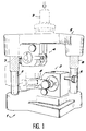
- the shear testing machine comprises a fixed plate 1, a mobile plate 2, a fixed jaw 3 fixed to the fixed plate 1 and a mobile jaw 4 fixed to the mobile plate 2. Furthermore, two columns 5 and 6 are fixed to the fixed plate 1 and extend across the width of a test piece E held between the jaws 3 and 4.
- the movable plate 2 is provided with bores which allow it to slide on columns 5 and 6 by means of intermediate ball bearings 7 and 8, and it carries an upper end piece 9 intended for the attachment of weight or for the introduction of forces making it possible to adjust the value of the force of shear introduced.
- the upper end piece 9 is just above the gap between the two jaws 3 and 4, and moreover the columns 5 and 6 surround the two jaws 3 and 4 symmetrically.
- the embodiment shown comprises vertical columns 5 and 6 and the movable plate 2 above the fixed plate 1, but other arrangements can be adopted.
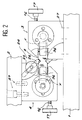
- jaws 3 and 4 As they are similar and arranged symmetrically with respect to the central point of the machine, only one will be described.
- Each of the jaws 3 or 4 essentially comprises a horseshoe piece 10 and a wedge 11.
- the horseshoe piece 10 comprises a first branch 12 fixed to a respective plate 1 or 2 and a second branch 13 directed towards the other plate.
- the inner side 14 of the first branch 12 is horizontal, but the internal face 15 of the second branch 13 is inclined and the corner 11 slides over it in the direction of the inclination corresponding to the longitudinal direction of the test piece E.
- a threaded rod 16 is therefore screwed into a thread of the horseshoe part 10.
- the threaded rod 16 is terminated by a knurled wheel 17 at one end and comprises at the other end a washer 18 trapped in a groove with a cross section T 19 vertical from corner 11.
- the angle of the corner 11 and the inclination of the inclined internal face 15 are such that the internal face 20 of the corner 11, directed towards the horizontal internal face 14, is also horizontal.
- the threaded rod 16 is therefore advanced, which displaces the wedge 11 in the longitudinal direction of the test piece E on the inclined internal face 15 and varies the distance between the horizontal internal faces 14 and 20 of the corner 11 and the first branch 12.
- the test piece E is of substantially rectangular shape and has a small thickness. Its longitudinal ends F are each gripped by one of the jaws 3 or 4 and its central part G which extends between the jaws 3 and 4 is weakened by two grooves H opposite one another, with sections at right angles and which extend from the lower and upper surfaces of the test piece E.
- the first branch 12 of the horseshoe pieces 10 comprises a centering device 24 constituted by a wheel 25 whose rotation makes it possible to adjust the advance of a pin 26 inclined at 45 ° to the horizontal.
- Each of the pawns 26 is housed in a notches H, rests on one of its faces at right angles by its end and on the other of its faces by its circumferential face. The advance of the pins 26 therefore makes it possible to achieve perfect longitudinal centering of the test piece E.
- the reference 27 generally designates positioning pins and screws for fixing the jaws 3 and 4 on the plates 1 and 2.
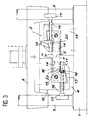
- the horseshoe pieces 10 are provided with two opposite bearings 28 and 29 on their external lateral faces 30 and 31, between the branches 12 and 13.
- the bearings 28 and 29 receive a shaft 32 which s 'extends between them and includes two threaded parts in opposite directions 33 and 34 as well as a wheel 35 for turning it.
- a pinch jaw 36 or 37 is engaged by screwing on one of the respective threaded parts 33 and 34. The rotation of the thumb wheel 35 therefore causes the pinch jaws 36 and 37 to move apart or move together according to a mutual axial movement with the shaft 32, in the thickness direction of the test piece E which it is therefore possible to grasp at its longitudinal ends between the corner 11 and the first branch 12, on opposite surfaces perpendicular to the thickness of the test tube E.
- a shoulder 38 is provided in the center of the shaft 32 to avoid damaging the gripping surfaces 39 and 40 of the gripping jaws 36 and 37 by bringing them into contact.
- FIGS. 3 and 5 show that the second branches 13 of the horseshoe pieces 10 are provided with a longitudinal slot 41 to allow the passage of the test piece E and its positioning in the jaws 3 and 4 according to the method which will now be described.
- the upper plate 2 is lifted so as to separate the jaws 3 and 4.
- the pinch jaws 36 and 37 are likewise removed from each of the jaws 3 and 4 and the corners 11 are moved back so as to clear the slots 41, as well as the centering pins 26.
- the state obtained is shown in solid lines in FIG. 1.
- test piece E is passed through the slots 41 while bringing the jaws 3 and 4 together until they are placed face to face, at the same height.
- the corners 11 are then advanced so as to cover the slots 41, preventing the specimen E from being removed, while wedging the latter between the horizontal surfaces 14 and 20.
- the centering pins 26 are then adjusted so as to achieve longitudinal centering of the test piece E.
- the clamping jaws 36 and 37 are brought together to grip the test piece according to its thickness.
- the shear test takes place by an introduction of forces on the end piece 9 after having removed the centering pins 26.
- test is static with a gradual increase in the force until the rupture of the test piece E if desired.
- dynamic shear tests are conceivable.
- test pieces E which are therefore subject to buckling.
- the tests can be carried out on all plausible materials, in particular on composite materials and ceramics.
Landscapes
- Physics & Mathematics (AREA)
- Health & Medical Sciences (AREA)
- Life Sciences & Earth Sciences (AREA)
- Chemical & Material Sciences (AREA)
- Analytical Chemistry (AREA)
- Biochemistry (AREA)
- General Health & Medical Sciences (AREA)
- General Physics & Mathematics (AREA)
- Immunology (AREA)
- Pathology (AREA)
- Investigating Strength Of Materials By Application Of Mechanical Stress (AREA)
- Transition And Organic Metals Composition Catalysts For Addition Polymerization (AREA)
- Glass Compositions (AREA)
Claims (6)
- Gerät zur Scherprüfung von Prüflingen (E) umfassend zwei untereinander verbundene Backen (3,4), in welchen die Prüflinge (E) mit den Enden der Längsseiten (F) erfaßt werden und welche gegeneinander in Richtung der Breite der Prüflinge verschiebbar sind, wobei die Backen aus zwei gegenseitig in Richtung der Breite der Prüflinge beweglichen Teilen (10,11) gebildet sind, die an zwei einander gegenüberliegenden Flächen der Längsenden (F) der Prüfling (E) zum Zwecke des Erfassens anliegen, dadurch gekennzeichnet, daß ein Paar Klemmbacken (36,37) jeder Backe zugeordnet sind, wobei die Klemmbackenpaare (36,37) mit den zugeordneten Backen mittels eines Stellmechanismus (32) verbunden sind, der eine gegenseitige Beweglichkeit der Klemmbacken jedes Paares in Richtung der Dicke der Prüflinge (E) und ein Abstützen auf zwei weiteren einander gegenüberliegenden Flächen der Längsenden der Prüflinge gewährleistet.
- Gerät zur Prüfung von Prüflingen nach Anspruch 1, da durch gekennzeichnet, daß die Stellmechanismen aus einer in einer der korrespondierenden Backen (3,4) drehbaren Spindel (32) gebildet sind, und die mit Gewindeabschnitten entgegengesetzten Sinnes (33,34) versehen ist, über die jede der Klemmbacken des betreffenden Paares verschraubbar ist.
- Gerät zur Überprüfung von Prüflingen nach einem der Ansprüche 1 oder 2, dadurch gekennzeichnet, daß eines der Teile der Backen ein Keil (11) ist, und das andere Teil der Backen aus zwei Schenkeln (12,13) in Form eines Hufeisens (10) gebildet ist, wobei der Keil auf einer Innenfläche (15) eines der Schenkel (12,13) gleitverschieblich ist, die zur Innenfläche (14) des anderen Schenkels gerichtet ist, wobei der Keil eine Fläche (20) aufweist, die gegen den anderen Schenkel (12) und parallel zur Innenfläche (14) des anderen Schenkels gerichtet ist.
- Gerät zur Prüfung von Prüflingen nach einem der Ansprüche 1 bis 3, dadurch gekennzeichnet, daß es zwei Platten (1,2) umfaßt, wobei auf jeder ein Backen (3,4) angeordnet ist, und daß zwei Säulen (5,6), die an einer der Platten (1) befestigt sind und in welchen die andere Platte (2) verschieblich ist, sich in Richtung der Breite der Prüflinge erstrecken, wobei die Backen (3,4) zwischen den Säulen angeordnet sind.
- Gerät zur Prüfung von Prüflingen nach den Ansprüchen 3 und 4, dadurch gekennzeichnet, daß der Schenkel (13) des hufeisenförmigen Teils (10) auf dem ein Keil gleitet in Langsrichtung der Prüflinge geschlitzt (41) ist, und daß der andere Schenkel (12) des hufeisenförmigen Teils an einer der Platten (1,2) befestigt ist.
- Gerät zur Prüfung von Prüflingen nach einem der Ansprüche 1 bis 5, dadurch gekennzeichnet, daß sie einen Anschlag zur Längspositionierung (26) der Prüflinge auf einem der Backen (3,4) umfaßt.
Priority Applications (1)
| Application Number | Priority Date | Filing Date | Title |
|---|---|---|---|
| AT91400961T ATE98772T1 (de) | 1990-04-12 | 1991-04-10 | Geraet zum scherpruefung von prueflingen. |
Applications Claiming Priority (2)
| Application Number | Priority Date | Filing Date | Title |
|---|---|---|---|
| FR9004727A FR2661000B1 (fr) | 1990-04-12 | 1990-04-12 | Machine d'essais d'eprouvettes en cisaillement. |
| FR9004727 | 1990-04-12 |
Publications (2)
| Publication Number | Publication Date |
|---|---|
| EP0452216A1 EP0452216A1 (de) | 1991-10-16 |
| EP0452216B1 true EP0452216B1 (de) | 1993-12-15 |
Family
ID=9395717
Family Applications (1)
| Application Number | Title | Priority Date | Filing Date |
|---|---|---|---|
| EP91400961A Expired - Lifetime EP0452216B1 (de) | 1990-04-12 | 1991-04-10 | Gerät zum Scherprüfung von Prüflingen |
Country Status (4)
| Country | Link |
|---|---|
| EP (1) | EP0452216B1 (de) |
| AT (1) | ATE98772T1 (de) |
| DE (1) | DE69100772T2 (de) |
| FR (1) | FR2661000B1 (de) |
Cited By (1)
| Publication number | Priority date | Publication date | Assignee | Title |
|---|---|---|---|---|
| US11365259B2 (en) | 2014-04-25 | 2022-06-21 | Pierre Fabre Medicament | IGF-1R antibody and its use as addressing vehicle for the treatment of cancer |
Families Citing this family (10)
| Publication number | Priority date | Publication date | Assignee | Title |
|---|---|---|---|---|
| FR2673723B1 (fr) * | 1991-03-08 | 1994-01-21 | Aerospatiale Ste Nationale Indle | Dispositif d'essais en compression d'eprouvettes pour essais en cisaillement interlaminaire et procedes d'essai en cisaillement d'eprouvettes, notamment d'eprouvettes courbes. |
| EP0687899B1 (de) * | 1994-06-14 | 2000-10-11 | Instituto Michanikis Ylikon Kai Geodomon A.E. | Probeform, um eine gleichmässige Verteilung der Scherkräfte während eines Tests zu erzeugen |
| FR2733048B1 (fr) * | 1995-04-12 | 1997-05-16 | Snecma | Dispositif de mesure de deformations d'une eprouvette soumise a un essai de cisaillement |
| DK200500062A (da) * | 2005-01-12 | 2006-07-13 | Forskningsct Risoe | Fikstur |
| GB2494177A (en) * | 2011-09-02 | 2013-03-06 | Univ Loughborough | Determining interlaminar shear mechanical properties of composite laminates |
| CN104677750B (zh) * | 2015-02-02 | 2017-11-24 | 南京航空航天大学 | 一种剪切测试装置及其操作方法 |
| CN106263278B (zh) * | 2016-08-11 | 2019-01-01 | 绍兴柯桥中茂化纤有限公司 | 一种鞋底稳固检验装置 |
| CN112067433B (zh) * | 2020-08-24 | 2023-09-22 | 中国飞机强度研究所 | 一种复合材料轨道剪切试验用辅助对中安装装置 |
| CN114166660B (zh) * | 2021-12-08 | 2024-10-29 | 南京工业大学 | 一种混凝土用锚栓剪切试验装置 |
| CN115201027B (zh) * | 2022-08-17 | 2024-07-09 | 哈尔滨工业大学 | 基于多轴疲劳试验机的板条试件弯剪耦合试验装置及方法 |
Family Cites Families (2)
| Publication number | Priority date | Publication date | Assignee | Title |
|---|---|---|---|---|
| FR1579091A (de) * | 1968-06-27 | 1969-08-22 | ||
| SU620869A1 (ru) * | 1975-12-09 | 1978-08-25 | Предприятие П/Я А-3605 | Приспособление дл испытани на срез пр моугольных образцов к испытательной машине |
-
1990
- 1990-04-12 FR FR9004727A patent/FR2661000B1/fr not_active Expired - Fee Related
-
1991
- 1991-04-10 EP EP91400961A patent/EP0452216B1/de not_active Expired - Lifetime
- 1991-04-10 DE DE91400961T patent/DE69100772T2/de not_active Expired - Fee Related
- 1991-04-10 AT AT91400961T patent/ATE98772T1/de not_active IP Right Cessation
Cited By (1)
| Publication number | Priority date | Publication date | Assignee | Title |
|---|---|---|---|---|
| US11365259B2 (en) | 2014-04-25 | 2022-06-21 | Pierre Fabre Medicament | IGF-1R antibody and its use as addressing vehicle for the treatment of cancer |
Also Published As
| Publication number | Publication date |
|---|---|
| EP0452216A1 (de) | 1991-10-16 |
| FR2661000B1 (fr) | 1992-08-07 |
| DE69100772D1 (de) | 1994-01-27 |
| FR2661000A1 (fr) | 1991-10-18 |
| ATE98772T1 (de) | 1994-01-15 |
| DE69100772T2 (de) | 1994-05-05 |
Similar Documents
| Publication | Publication Date | Title |
|---|---|---|
| EP0452216B1 (de) | Gerät zum Scherprüfung von Prüflingen | |
| CA1028478A (en) | Tightening grip | |
| FR2665033A1 (fr) | Dispositif de reglage pour micro-mouvements. | |
| EP1713610B1 (de) | Klemmwerkzeug, insbesondere lötzange, mit einem ausgleichssystem | |
| FR2507943A1 (fr) | Etaux d'etabli perfectionnes | |
| EP0504012B1 (de) | Druck-Testvorrichtung zur Zwischenschicht-Scherprüfung von Prüflingen, und Scherprüfungsverfahren, insbesondere für biegsame Prüflinge | |
| EP2326913B1 (de) | Einrichtung zum messen und korregieren eines parallelismusfehlers eines kernbrennstabs | |
| FR2559579A1 (fr) | Dispositif pour monter solidement un boitier de cellule dynamometrique sur une poutre | |
| FR2722881A1 (fr) | Dispositif de prehension pour la realisation d'essais de traction a haute temperature sur des eprouvettes plates en materiau fragile | |
| FR3048681A1 (fr) | Receptacle servant au transport d'objets dans une chaine de production | |
| FR2976668A1 (fr) | Dispositif de maintien transversal d'une eprouvette longitudinale et appareillage pour la caracterisation mecanique en flexion d'une telle eprouvette. | |
| FR2667152A1 (fr) | Dispositif d'essai en traction et compression sur une eprouvette apres simulation de rentree en atmosphere. | |
| FR3101421A1 (fr) | Dispositif pour appliquer sur un échantillon une charge bi-axiale différentielle | |
| EP2827008A1 (de) | Vorrichtung zum Spannen von Muttern | |
| EP1476761B1 (de) | Kontaktbetätigungsglied mit kontaktkraftregelung | |
| FR2480166A1 (fr) | Dispositif pour maintenir des cles dans une machine a reproduire les cles | |
| EP0918264B9 (de) | Positionseinstellvorrichtung für eine auf einem Uhrwerkhemmungsanker montierte Palette | |
| FR2894670A1 (fr) | Dispositif de serrage pour une eprouvette plate en materiau anisotrope. | |
| FR2735235A1 (fr) | Appareil pour effectuer des essais mecaniques de flexion sur une piece | |
| FR2504463A1 (fr) | Isolateur de section pour ligne aerienne de traction electrique de chemin de fer, et procede et appareil pour sa mise en place | |
| EP1743154A1 (de) | Vorrichtung zur steuerung der sicherheitsspannung von länglichen gegenständen, insbesondere sicherheitsgurten und steuerverfahren | |
| EP0227546B1 (de) | Vorrichtungen zum Spannen von Zugelementen vor der Verankerung | |
| EP3387495B1 (de) | Rattrapante-mechanismus | |
| CH451984A (fr) | Procédé de fixation de rails de chemins de fer et de pièces de métal semblables allongées dans les plateaux d'une machine à souder par résistance, et dispositif pour la mise en oeuvre du procédé | |
| FR2686977A1 (fr) | Dispositif de fluage d'une eprouvette. |
Legal Events
| Date | Code | Title | Description |
|---|---|---|---|
| PUAI | Public reference made under article 153(3) epc to a published international application that has entered the european phase |
Free format text: ORIGINAL CODE: 0009012 |
|
| AK | Designated contracting states |
Kind code of ref document: A1 Designated state(s): AT DE ES GB NL |
|
| 17P | Request for examination filed |
Effective date: 19920324 |
|
| 17Q | First examination report despatched |
Effective date: 19920930 |
|
| GRAA | (expected) grant |
Free format text: ORIGINAL CODE: 0009210 |
|
| AK | Designated contracting states |
Kind code of ref document: B1 Designated state(s): AT DE ES GB NL |
|
| PG25 | Lapsed in a contracting state [announced via postgrant information from national office to epo] |
Ref country code: NL Effective date: 19931215 Ref country code: GB Effective date: 19931215 Ref country code: ES Free format text: THE PATENT HAS BEEN ANNULLED BY A DECISION OF A NATIONAL AUTHORITY Effective date: 19931215 |
|
| REF | Corresponds to: |
Ref document number: 98772 Country of ref document: AT Date of ref document: 19940115 Kind code of ref document: T |
|
| REF | Corresponds to: |
Ref document number: 69100772 Country of ref document: DE Date of ref document: 19940127 |
|
| PG25 | Lapsed in a contracting state [announced via postgrant information from national office to epo] |
Ref country code: AT Effective date: 19940410 |
|
| NLV1 | Nl: lapsed or annulled due to failure to fulfill the requirements of art. 29p and 29m of the patents act | ||
| GBV | Gb: ep patent (uk) treated as always having been void in accordance with gb section 77(7)/1977 [no translation filed] |
Effective date: 19931215 |
|
| PLBE | No opposition filed within time limit |
Free format text: ORIGINAL CODE: 0009261 |
|
| STAA | Information on the status of an ep patent application or granted ep patent |
Free format text: STATUS: NO OPPOSITION FILED WITHIN TIME LIMIT |
|
| 26N | No opposition filed | ||
| PG25 | Lapsed in a contracting state [announced via postgrant information from national office to epo] |
Ref country code: DE Effective date: 19950103 |