EP0452219B1 - Endoprothese-Katheter - Google Patents
Endoprothese-Katheter Download PDFInfo
- Publication number
- EP0452219B1 EP0452219B1 EP91400966A EP91400966A EP0452219B1 EP 0452219 B1 EP0452219 B1 EP 0452219B1 EP 91400966 A EP91400966 A EP 91400966A EP 91400966 A EP91400966 A EP 91400966A EP 0452219 B1 EP0452219 B1 EP 0452219B1
- Authority
- EP
- European Patent Office
- Prior art keywords
- catheter
- sleeve
- distal end
- morphological
- catheter according
- Prior art date
- Legal status (The legal status is an assumption and is not a legal conclusion. Google has not performed a legal analysis and makes no representation as to the accuracy of the status listed.)
- Expired - Lifetime
Links
- 230000000877 morphologic effect Effects 0.000 claims abstract description 37
- 239000012530 fluid Substances 0.000 claims description 19
- 239000012528 membrane Substances 0.000 claims description 12
- 206010003210 Arteriosclerosis Diseases 0.000 description 9
- 208000037260 Atherosclerotic Plaque Diseases 0.000 description 9
- 230000005855 radiation Effects 0.000 description 4
- 239000000523 sample Substances 0.000 description 4
- 239000000463 material Substances 0.000 description 3
- 230000015572 biosynthetic process Effects 0.000 description 2
- 210000004369 blood Anatomy 0.000 description 2
- 239000008280 blood Substances 0.000 description 2
- 230000017531 blood circulation Effects 0.000 description 2
- 230000004087 circulation Effects 0.000 description 2
- 230000010339 dilation Effects 0.000 description 2
- 239000007789 gas Substances 0.000 description 2
- 238000011065 in-situ storage Methods 0.000 description 2
- 229920000126 latex Polymers 0.000 description 2
- 239000004816 latex Substances 0.000 description 2
- 239000007788 liquid Substances 0.000 description 2
- 238000000034 method Methods 0.000 description 2
- 210000005259 peripheral blood Anatomy 0.000 description 2
- 239000011886 peripheral blood Substances 0.000 description 2
- 238000006116 polymerization reaction Methods 0.000 description 2
- 239000004593 Epoxy Substances 0.000 description 1
- 239000004698 Polyethylene Substances 0.000 description 1
- NIXOWILDQLNWCW-UHFFFAOYSA-N acrylic acid group Chemical group C(C=C)(=O)O NIXOWILDQLNWCW-UHFFFAOYSA-N 0.000 description 1
- 210000001367 artery Anatomy 0.000 description 1
- 239000000560 biocompatible material Substances 0.000 description 1
- 230000005540 biological transmission Effects 0.000 description 1
- 238000006243 chemical reaction Methods 0.000 description 1
- 239000011248 coating agent Substances 0.000 description 1
- 238000000576 coating method Methods 0.000 description 1
- 230000008030 elimination Effects 0.000 description 1
- 238000003379 elimination reaction Methods 0.000 description 1
- 239000000835 fiber Substances 0.000 description 1
- 239000012535 impurity Substances 0.000 description 1
- 230000002401 inhibitory effect Effects 0.000 description 1
- 239000013307 optical fiber Substances 0.000 description 1
- -1 polyethylene Polymers 0.000 description 1
- 229920000573 polyethylene Polymers 0.000 description 1
- 229920001296 polysiloxane Polymers 0.000 description 1
- 230000002787 reinforcement Effects 0.000 description 1
- 239000011347 resin Substances 0.000 description 1
- 229920005989 resin Polymers 0.000 description 1
- 238000007711 solidification Methods 0.000 description 1
- 230000008023 solidification Effects 0.000 description 1
- 238000002604 ultrasonography Methods 0.000 description 1
Images

Classifications
-
- A—HUMAN NECESSITIES
- A61—MEDICAL OR VETERINARY SCIENCE; HYGIENE
- A61F—FILTERS IMPLANTABLE INTO BLOOD VESSELS; PROSTHESES; DEVICES PROVIDING PATENCY TO, OR PREVENTING COLLAPSING OF, TUBULAR STRUCTURES OF THE BODY, e.g. STENTS; ORTHOPAEDIC, NURSING OR CONTRACEPTIVE DEVICES; FOMENTATION; TREATMENT OR PROTECTION OF EYES OR EARS; BANDAGES, DRESSINGS OR ABSORBENT PADS; FIRST-AID KITS
- A61F2/00—Filters implantable into blood vessels; Prostheses, i.e. artificial substitutes or replacements for parts of the body; Appliances for connecting them with the body; Devices providing patency to, or preventing collapsing of, tubular structures of the body, e.g. stents
- A61F2/82—Devices providing patency to, or preventing collapsing of, tubular structures of the body, e.g. stents
-
- A—HUMAN NECESSITIES
- A61—MEDICAL OR VETERINARY SCIENCE; HYGIENE
- A61F—FILTERS IMPLANTABLE INTO BLOOD VESSELS; PROSTHESES; DEVICES PROVIDING PATENCY TO, OR PREVENTING COLLAPSING OF, TUBULAR STRUCTURES OF THE BODY, e.g. STENTS; ORTHOPAEDIC, NURSING OR CONTRACEPTIVE DEVICES; FOMENTATION; TREATMENT OR PROTECTION OF EYES OR EARS; BANDAGES, DRESSINGS OR ABSORBENT PADS; FIRST-AID KITS
- A61F2/00—Filters implantable into blood vessels; Prostheses, i.e. artificial substitutes or replacements for parts of the body; Appliances for connecting them with the body; Devices providing patency to, or preventing collapsing of, tubular structures of the body, e.g. stents
- A61F2/95—Instruments specially adapted for placement or removal of stents or stent-grafts
- A61F2/958—Inflatable balloons for placing stents or stent-grafts
-
- A—HUMAN NECESSITIES
- A61—MEDICAL OR VETERINARY SCIENCE; HYGIENE
- A61M—DEVICES FOR INTRODUCING MEDIA INTO, OR ONTO, THE BODY; DEVICES FOR TRANSDUCING BODY MEDIA OR FOR TAKING MEDIA FROM THE BODY; DEVICES FOR PRODUCING OR ENDING SLEEP OR STUPOR
- A61M25/00—Catheters; Hollow probes
- A61M25/10—Balloon catheters
- A61M25/1002—Balloon catheters characterised by balloon shape
Definitions
- the present invention relates to a catheter for morphological conduit capable of placing a stent, temporary or permanent, inside said morphological conduit.
- the catheter in accordance with the present invention is intended to conclude an intervention carried out with a dilation probe or laser radiation in a morphological duct at least partially blocked by an atheroma.
- the invention will be more particularly described below in connection with this application, which however should not be considered as a limitation of the invention.
- the wall of the morphological duct has, at the site of the atheroma eliminated, numerous asperities or membranes suitable for formation of a new atheroma.
- the object of the present invention is in particular to remedy this drawback.
- the catheter for morphological conduit comprising an inflatable balloon, disposed at the distal end of said catheter and connected to the proximal end of said catheter by at least one inflation duct capable of being connected to an inflation device, said inflatable balloon being able to assume either a deflated state for which it is pressed against said distal end of said catheter, that is to say an inflated state for which it is pressed by its external wall against the internal wall of said morphological duct, is characterized in that said inflatable balloon has the shape of a sleeve surrounding said distal end of said catheter and connected to the latter by a flexible connector, itself connected to said inflation conduit and in that, in the inflated state, said sleeve provides an annular space between its internal wall and said distal end of said catheter.
- said sleeve can, in the deflated state, be inserted without difficulty inside said morphological duct, at the level of an eliminated atheroma, via said catheter, then, once put in place, be inflated to constitute in situ a prosthesis with an annular section capable of covering, and therefore inhibiting, the roughness and other elements liable to initiate the formation of a new atheroma.
- the inflatable sleeve can also be used as a means of radial expansion of said morphological duct, in place of the inflatable balloons which are generally provided with known dilatation probes, and that in all circumstances - that it whether or not there is an atheroma-- the catheter sleeve according to the invention constitutes a local reinforcement of said morphological duct.
- Such a known inflatable balloon probe which corresponds to the precharacterizing part of claim 1, is for example described by the document US-A-4 681 564.
- several forms of balloons are given by way of examples.
- none of them relates to a sleeve capable of constituting a prosthesis in situ, in particular because all the forms of balloons described close the morphological duct into which they are introduced.
- document WO-88/05671 describes a medical device which can be inserted into a morphological conduit to isolate the wall thereof from the liquid which circulates therein.
- This device comprises a sleeve, which does not have the structure of an inflatable balloon, but which is associated with at least one auxiliary inflation balloon, which can optionally be removed from said morphological duct after having pressed said sleeve against the wall thereof .
- an elastic membrane surrounding said sleeve is preferably provided.
- said sleeve is compressed radially in the direction of the catheter, which facilitates the introduction of the latter into the morphological duct. The radial expansion of the sleeve then takes place against the elastic action of said membrane.
- Such a membrane is made of a biocompatible implantable material, such as silicone or latex.
- this membrane is perforated and may even have the form of a net, so as not to oppose the peripheral blood circulation, when the sleeve is itself perforated and is arranged to the intersection of morphological conduits.
- the sleeve is intended to form a temporary prosthesis which retains its radially expanded form only under the action of the pressure exerted by a fluid introduced into the inflation duct by said inflation device, it can be seen that, when the 'the inflating fluid is removed, said elastic membrane returns the deflated sleeve in a tight position around the distal end of the catheter, which allows the catheter and its sleeve to be extracted from said morphological duct.
- said inflation conduit is incorporated into said catheter and is connected to said sleeve by a flexible connector.
- said sleeve is made integral with said catheter by said connector.
- an inflation fluid capable of stiffening said sleeve is inflated to said sleeve and steps are taken to ensure that said flexible connector is capable of to be broken.
- the catheter can be taken out of the morphological conduit while leaving said inflated sleeve there.
- an inflation fluid drain conduit connecting said sleeve to the proximal end of the catheter.
- this emptying duct like the inflation duct, is incorporated into said catheter and is connected to said sleeve by a flexible connector. In the case of a permanent prosthesis, the latter flexible connection is also liable to be broken.
- the sleeve is formed by a tube wound in a helical coil or by a double-walled tube.
- said turns are not contiguous or openings are provided in the double-walled tube.
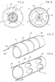
- Figure 1 is a schematic longitudinal section illustrating the establishment of the deflated sleeve inside a morphological conduit.
- Figure 2 is a cross section along line II-II of Figure 1.
- Figure 3 is a schematic longitudinal section illustrating the establishment of the inflated sleeve inside the morphological duct.
- FIG. 4 is a cross section along the line IV-IV of FIG. 3.
- Figure 5 shows in enlarged perspective an embodiment of the sleeve, in the form of a coil.
- Figure 6 shows, also in enlarged perspective, an alternative embodiment of the sleeve according to the invention.
- the distal end 2 of the catheter 1 is surrounded by an inflatable sleeve 6, itself compressed towards said distal end 2 by an elastic membrane 7.
- conduits 8 and 9 respectively connected to said inflatable sleeve 6 by flexible connectors 10 and 11.
- the proximal end (not shown) of the conduit 8 is connected to an inflation device (also not shown) capable of addressing an inflation fluid inside the sleeve 6, for example gas or a liquid at a pressure of 2 or 3 bars, via said conduit 8 and the flexible connector 10.
- an inflation device also not shown
- the fluid entering the sleeve can exit through the flexible connector 11 and the conduit 9, so that said fluid scans the sleeve.
- the pressure inside said sleeve can be adjusted.
- the catheter 1 is introduced into the morphological conduit 3, by means of the guide support 5 and put in place precisely by means of radiopaque markers (not shown).
- inflation fluid is sent to the sleeve 6, as indicated above.
- the sleeve 6 then expands until its outer wall covered with the membrane 7 is pressed against the inner wall 3a of the morphological conduit 3, an annular space 12 is then formed between said sleeve 6 and the distal end 2 of the catheter 1 (see Figures 3 and 4).
- the pressure of the inflation fluid in order to obtain good adhesion of the sleeve 6 on the internal wall 3a of the morphological conduit 3, it was sufficient for the pressure of the inflation fluid to be 2 to 3 bars, pressure which is tolerable by the patient.
- the diameter D of the morphological conduit 3 is less, for example by about 10%, than the external diameter that would take the sleeve 6 at its operating pressure inside said conduit 3 swollen, if it was not enclosed in the morphological canal 3.
- the simple circulation of the fluid through the sleeve 6 can maintain the rigidity of the latter in the inflated state.
- the inflation fluid can be a resin (acrylic, epoxy) or a polymerizable latex, preferably at room temperature. After polymerization of said fluid, the sleeve keeps its rigid shape inflated.
- weakened zones 10a and 11a on the flexible connectors 10 and 11, respectively, making it possible to break said connections, for example by twisting and / or by pulling the catheter 1.
- the catheter 1 can be removed from the morphological conduit 3, only the inflated rigid sleeve 6 remaining in place.
- the polymerization of the sleeve 6 in the inflated state can also be obtained by introducing into the sleeve 6 a material which, by reaction with the inflation fluid, is capable of stiffening the inflated sleeve.
- the catheter 1 will be of the disposable type, because the inflation fluid will also be solidified in conduits 8 and 9.
- the guide support 5 may be replaced, during the intervention, by an optical fiber capable of transmitting the energy of radiation or by a tube coated with an inner coating allowing ensure the transmission of ultrasound from an external source to the part to be treated.
- the inflatable sleeve 6 can be produced in different ways. Preferably, it is made of a preformable material, such as an irradiated polyethylene. Thus, its shape in the inflated state can be adapted to that of the location of the conduit 3, where it is intended to form a prosthesis.
- the sleeve 6 is constituted by a preformed flat tube 13 wound in a helical coil. It will be noted that this embodiment is advantageous because, between the non-contiguous turns of the coil, the sleeve 6 has spaces 14 through which the blood can circulate. Thus, if the sleeve is placed in a conduit 3, at the intersection with one or more other morphological conduits, the blood can continue to circulate between these conduits, through the spaces 14.
- the membrane 7 is itself perforated or, better, has the shape of a net.
- the sleeve may consist of several helical coils with nested turns, with independent inflations and inflations. These coils may have different diameters and internal and external communications can be envisaged between said coils.
- the sleeve 6 is formed by two welded walls 15 and 16, lumens 17 being formed in the side wall of said sleeve, to ensure peripheral blood circulation through the double wall of said sleeve.
- the sleeve 6 is made of a biocompatible material.
Landscapes
- Health & Medical Sciences (AREA)
- Engineering & Computer Science (AREA)
- Biomedical Technology (AREA)
- Heart & Thoracic Surgery (AREA)
- Life Sciences & Earth Sciences (AREA)
- Animal Behavior & Ethology (AREA)
- Veterinary Medicine (AREA)
- Public Health (AREA)
- General Health & Medical Sciences (AREA)
- Transplantation (AREA)
- Vascular Medicine (AREA)
- Oral & Maxillofacial Surgery (AREA)
- Cardiology (AREA)
- Child & Adolescent Psychology (AREA)
- Biophysics (AREA)
- Pulmonology (AREA)
- Anesthesiology (AREA)
- Hematology (AREA)
- Media Introduction/Drainage Providing Device (AREA)
- Materials For Medical Uses (AREA)
- Prostheses (AREA)
- Infusion, Injection, And Reservoir Apparatuses (AREA)
Claims (12)
- Katheder (1) für eine Leitung (3) eines Organismus, die einen aufblähbaren Ballon (6) umfaßt, der am distalen Ende (2) des Katheders angeordnet ist und mit dem proximalen Ende des Katheders durch wenigstens eine Leitung zum Aufblähen (8) verbunden ist, die dafür geeignet ist, mit einer Aufblähvorrichtung verbunden zu werden, wobei der aufblähbare Ballon (6) entweder einen leeren Zustand, in dem er am distalen Ende des Katheders anliegt, oder einen aufgeblähten Zustand, in dem er mit seiner äußeren Seitenwand an der inneren Seitenwand (3a) der Organismusleitung (3) anliegt, einnehmen kann,
dadurch gekennzeichnet, daß der aufblähbare Ballon (6) die Form einer Hülse aufweist, die das distale Ende (2) des Katheders umschließt und mit diesem über eine dehnbare Verbindung (10) verbunden ist, die ihrerseits mit der Aufblähleitung (8) verbunden ist und dadurch gekennzeichnet, daß in aufgeblähtem Zustand die Hülse einen ringförmigen Zwischenraum (12) zwischen ihrer inneren Seitenwand und dem distalen Ende des Katheders ausbildet. - Katheder nach Anspruch 1, dadurch gekennzeichnet, daß er eine elastische Membran (7) umfaßt, die die Hülse (6) umschließt und diese gegen das distale Ende (2) des Katheders zusammendrückt.
- Katheder nach Anspruch 2, dadurch gekennzeichnet, daß die elastische Membran (7) gelocht ist.
- Katheder nach einem der Ansprüche 1 bis 3, dadurch gekennzeichnet, daß die Aufblähvorrichtung ein Aufblähfluid zuführt, das in der Lage ist, die Hülse in ihrem aufgeblähten Zustand zu versteifen und dadurch, daß die dehnbare Verbindung dafür ausgebildet ist, abgebrochen zu werden (siehe 10a).
- Katheder nach einem der Ansprüche 1 bis 4, dadurch gekennzeichnet, daß er außerdem eine Entleerungsleitung (9) umfaßt, die die Hülse über eine die Hülse mit dem distalen Ende des Katheders verbindende dehnbare Verbindung (11) mit dem proximalen Ende des Katheders verbindet.
- Katheder nach Anspruch 5, in dem das Aufblähfluid dazu geeignet ist, die Hülse in aufgeblähtem Zustand zu versteifen, dadurch gekennzeichnet, daß die dehnbare Verbindung (11) dafür ausgebildet ist, abgebrochen zu werden (siehe 11a).
- Katheder nach einem der Ansprüche 1 bis 6, dadurch gekennzeichnet, daß die Hülse (6) durch eine Röhre (13) gebildet wird, die spiralförmig aufgerollt ist.
- Katheder nach Anspruch 7, dadurch gekennzeichnet, daß die Windungen der Spirale nicht fugendicht miteinander verbunden sind.
- Katheder nach einem der Ansprüche 1 bis 6, dadurch gekennzeichnet, daß die Hülse (6) eine Röhre mit doppelter Wand (15, 16) ist.
- Katheder nach Anspruch 9, dadurch gekennzeichnet, daß die doppelwandige Röhre von seitlichen Öffnungen (17) durchsetzt ist.
- Katheder nach einem der Ansprüche 1 bis 10, dadurch gekennzeichnet, daß die Hülse vorgeformt ist.
- Katheder nach Anspruch 11, dadurch gekennzeichnet, daß der äußere Durchmesser der Hülse, wenn sie außerhalb der Organismusleitung (3) unter dem Druck, der während der Benutzung in deren Inneren herrscht, aufgeblasen ist, um ungefähr 10% größer ist als der Durchmesser der Organismusleitung.
Applications Claiming Priority (2)
| Application Number | Priority Date | Filing Date | Title |
|---|---|---|---|
| FR9004840 | 1990-04-13 | ||
| FR9004840A FR2660867B1 (fr) | 1990-04-13 | 1990-04-13 | Catheter a endoprothese. |
Publications (2)
| Publication Number | Publication Date |
|---|---|
| EP0452219A1 EP0452219A1 (de) | 1991-10-16 |
| EP0452219B1 true EP0452219B1 (de) | 1994-06-15 |
Family
ID=9395789
Family Applications (1)
| Application Number | Title | Priority Date | Filing Date |
|---|---|---|---|
| EP91400966A Expired - Lifetime EP0452219B1 (de) | 1990-04-13 | 1991-04-10 | Endoprothese-Katheter |
Country Status (8)
| Country | Link |
|---|---|
| US (1) | US5312339A (de) |
| EP (1) | EP0452219B1 (de) |
| JP (1) | JPH04224767A (de) |
| AT (1) | ATE107181T1 (de) |
| DE (1) | DE69102478T2 (de) |
| DK (1) | DK0452219T3 (de) |
| ES (1) | ES2055971T3 (de) |
| FR (1) | FR2660867B1 (de) |
Families Citing this family (15)
| Publication number | Priority date | Publication date | Assignee | Title |
|---|---|---|---|---|
| NL9101159A (nl) * | 1991-07-03 | 1993-02-01 | Industrial Res Bv | Vormvast te maken uitzetbare ring, cylinder of huls. |
| NL9300500A (nl) * | 1993-03-22 | 1994-10-17 | Industrial Res Bv | Uitzetbare, holle huls voor het plaatselijk ondersteunen en/of versterken van een lichaamsvat, alsmede werkwijze voor het vervaardigen daarvan. |
| DE4401227C2 (de) * | 1994-01-18 | 1999-03-18 | Ernst Peter Prof Dr M Strecker | In den Körper eines Patienten perkutan implantierbare Endoprothese |
| JP2660318B2 (ja) * | 1994-04-15 | 1997-10-08 | 株式会社エヌアンドエム | 胆道狭窄部の内瘻用アッセンブリ |
| US5649977A (en) * | 1994-09-22 | 1997-07-22 | Advanced Cardiovascular Systems, Inc. | Metal reinforced polymer stent |
| US5545135A (en) * | 1994-10-31 | 1996-08-13 | Boston Scientific Corporation | Perfusion balloon stent |
| US5833672A (en) * | 1994-12-12 | 1998-11-10 | Nippon Zeon Co., Ltd. | Double tube, balloon catheter produced by using double tube, and process for producing balloon catheter |
| US5833707A (en) * | 1995-07-05 | 1998-11-10 | Advanced Cardiovascular Systems, Inc. | Removable stent and method of deployment |
| US5782907A (en) * | 1995-07-13 | 1998-07-21 | Devices For Vascular Intervention, Inc. | Involuted spring stent and graft assembly and method of use |
| NL1003178C2 (nl) * | 1996-05-21 | 1997-11-25 | Cordis Europ | Buisvormige prothese van uithardbaar materiaal. |
| US6702849B1 (en) | 1999-12-13 | 2004-03-09 | Advanced Cardiovascular Systems, Inc. | Method of processing open-celled microcellular polymeric foams with controlled porosity for use as vascular grafts and stent covers |
| US20070225799A1 (en) * | 2006-03-24 | 2007-09-27 | Medtronic Vascular, Inc. | Stent, intraluminal stent delivery system, and method of treating a vascular condition |
| US8909316B2 (en) | 2011-05-18 | 2014-12-09 | St. Jude Medical, Cardiology Division, Inc. | Apparatus and method of assessing transvascular denervation |
| EP2709517B1 (de) * | 2011-05-18 | 2017-01-11 | St. Jude Medical, Inc. | Vorrichtung zur beurteilung einer transvaskulären denervierung |
| JP6153121B2 (ja) * | 2012-05-25 | 2017-06-28 | 国立大学法人 香川大学 | 領域確保用器具 |
Family Cites Families (16)
| Publication number | Priority date | Publication date | Assignee | Title |
|---|---|---|---|---|
| US3996938A (en) * | 1975-07-10 | 1976-12-14 | Clark Iii William T | Expanding mesh catheter |
| USRE32348E (en) * | 1976-04-29 | 1987-02-10 | Miniature balloon catheter method and apparatus | |
| US4503569A (en) * | 1983-03-03 | 1985-03-12 | Dotter Charles T | Transluminally placed expandable graft prosthesis |
| US4763653A (en) * | 1985-02-19 | 1988-08-16 | Rockey Arthur G | Medical sleeve |
| US4681564A (en) * | 1985-10-21 | 1987-07-21 | Landreneau Michael D | Catheter assembly having balloon extended flow path |
| US4650466A (en) * | 1985-11-01 | 1987-03-17 | Angiobrade Partners | Angioplasty device |
| DE3640745A1 (de) * | 1985-11-30 | 1987-06-04 | Ernst Peter Prof Dr M Strecker | Katheter zum herstellen oder erweitern von verbindungen zu oder zwischen koerperhohlraeumen |
| US4762130A (en) * | 1987-01-15 | 1988-08-09 | Thomas J. Fogarty | Catheter with corkscrew-like balloon |
| JPH088933B2 (ja) * | 1987-07-10 | 1996-01-31 | 日本ゼオン株式会社 | カテ−テル |
| JPS6446477A (en) * | 1987-08-13 | 1989-02-20 | Terumo Corp | Catheter |
| FR2626476B1 (fr) * | 1988-02-01 | 1997-10-17 | Boussignac Georges | Sonde destinee a etre introduite a l'interieur d'un corps vivant |
| US4877031A (en) * | 1988-07-22 | 1989-10-31 | Advanced Cardiovascular Systems, Inc. | Steerable perfusion dilatation catheter |
| US5160321A (en) * | 1988-11-23 | 1992-11-03 | Harvinder Sahota | Balloon catheters |
| US5037392A (en) * | 1989-06-06 | 1991-08-06 | Cordis Corporation | Stent-implanting balloon assembly |
| US5108370A (en) * | 1989-10-03 | 1992-04-28 | Paul Walinsky | Perfusion balloon catheter |
| US5071407A (en) * | 1990-04-12 | 1991-12-10 | Schneider (U.S.A.) Inc. | Radially expandable fixation member |
-
1990
- 1990-04-13 FR FR9004840A patent/FR2660867B1/fr not_active Expired - Fee Related
-
1991
- 1991-04-08 US US07/682,591 patent/US5312339A/en not_active Expired - Fee Related
- 1991-04-10 AT AT91400966T patent/ATE107181T1/de active
- 1991-04-10 DK DK91400966.7T patent/DK0452219T3/da active
- 1991-04-10 ES ES91400966T patent/ES2055971T3/es not_active Expired - Lifetime
- 1991-04-10 EP EP91400966A patent/EP0452219B1/de not_active Expired - Lifetime
- 1991-04-10 DE DE69102478T patent/DE69102478T2/de not_active Expired - Fee Related
- 1991-04-12 JP JP3079640A patent/JPH04224767A/ja active Pending
Also Published As
| Publication number | Publication date |
|---|---|
| DE69102478T2 (de) | 1994-11-03 |
| FR2660867B1 (fr) | 1998-07-10 |
| ATE107181T1 (de) | 1994-07-15 |
| EP0452219A1 (de) | 1991-10-16 |
| ES2055971T3 (es) | 1994-09-01 |
| DK0452219T3 (da) | 1994-07-11 |
| FR2660867A1 (fr) | 1991-10-18 |
| JPH04224767A (ja) | 1992-08-14 |
| US5312339A (en) | 1994-05-17 |
| DE69102478D1 (de) | 1994-07-21 |
Similar Documents
| Publication | Publication Date | Title |
|---|---|---|
| EP0452219B1 (de) | Endoprothese-Katheter | |
| EP0684802B1 (de) | Prothese zur behandlung eines lumens oder eines natürlichen kanals, insbesondere urethrale endoprothese | |
| EP1315458B1 (de) | Vaskuläre okklusionsvorrichtung, sowie gerät zu ihrer verwendung | |
| EP0621793B1 (de) | Dilatationskatheter | |
| US6139572A (en) | Delivery system for intraluminal vascular grafts | |
| CH671875A5 (de) | ||
| WO1997016217A1 (fr) | Dispositif d'angioplastie pour bifurcation arterielle | |
| US20020116048A1 (en) | Endovascular graft | |
| EP0897309B1 (de) | Katheter zur lokalen verabreichung einer therapeutisch aktiven substanz | |
| FR2853521A1 (fr) | Dispositif de dilatation d'un vaisseau et introducteur d'implant vasculaire | |
| FR2704434A1 (fr) | Ensemble intravasculaire à cathéter. | |
| FR2624747A1 (fr) | Dispositifs endo-arteriels amovibles destines a reparer des decollements de parois des arteres | |
| EP1233731A1 (de) | Perkutane vorrichtung zum ersetzen einer herzklappe | |
| JPH10507667A (ja) | バルーン膨張可能なステント/グラフト供給装置 | |
| EP1865886A2 (de) | In einem blutstromkanal zu implantierende ausrüstung und verwandte röhrenförmige endoprothese | |
| US20060167538A1 (en) | Inflatable biliary stent | |
| EP0821598A1 (de) | Temporäre abdichtungsvorrichtung für ein gefäss des menschlichen körpers, insbesondere geeignet für gegendruckherzunterstützng | |
| FR2797390A1 (fr) | Dispositif pour traiter un conduit corporel qui presente au moins une obstruction partielle | |
| FR2872696A1 (fr) | Introducteur pour intervention endoluminale | |
| FR2843297A1 (fr) | Ensemble medical et procede pour la sortie controlee d'une prothese expansible dans un conduit corporel | |
| EP0935976B1 (de) | Flexibler, biokompatibler Schaft zur Implantation in einen Körpergang und eine mit diesem Schaft ausgerüstete Vorrichtung | |
| CA2040873A1 (fr) | Catheter a endoprothese | |
| EP0974375B1 (de) | Vorrichung mit einem Ballon mit nominal einstellbarem Durchmesser | |
| FR2768921A1 (fr) | Ensemble comprenant une prothese intraluminale et un moyen d'etancheite de cette prothese | |
| FR2850285A1 (fr) | Dispositif a fil de guidage pour la protection distale temporaire contre l'embolie. |
Legal Events
| Date | Code | Title | Description |
|---|---|---|---|
| PUAI | Public reference made under article 153(3) epc to a published international application that has entered the european phase |
Free format text: ORIGINAL CODE: 0009012 |
|
| AK | Designated contracting states |
Kind code of ref document: A1 Designated state(s): AT BE CH DE DK ES GB GR IT LI LU NL SE |
|
| 17P | Request for examination filed |
Effective date: 19911029 |
|
| 17Q | First examination report despatched |
Effective date: 19930312 |
|
| GRAA | (expected) grant |
Free format text: ORIGINAL CODE: 0009210 |
|
| AK | Designated contracting states |
Kind code of ref document: B1 Designated state(s): AT BE CH DE DK ES GB GR IT LI LU NL SE |
|
| REF | Corresponds to: |
Ref document number: 107181 Country of ref document: AT Date of ref document: 19940715 Kind code of ref document: T |
|
| REG | Reference to a national code |
Ref country code: DK Ref legal event code: T3 |
|
| GBT | Gb: translation of ep patent filed (gb section 77(6)(a)/1977) |
Effective date: 19940621 |
|
| REF | Corresponds to: |
Ref document number: 69102478 Country of ref document: DE Date of ref document: 19940721 |
|
| REG | Reference to a national code |
Ref country code: GR Ref legal event code: FG4A Free format text: 3012137 |
|
| REG | Reference to a national code |
Ref country code: ES Ref legal event code: FG2A Ref document number: 2055971 Country of ref document: ES Kind code of ref document: T3 |
|
| ITF | It: translation for a ep patent filed | ||
| EAL | Se: european patent in force in sweden |
Ref document number: 91400966.7 |
|
| PLBE | No opposition filed within time limit |
Free format text: ORIGINAL CODE: 0009261 |
|
| STAA | Information on the status of an ep patent application or granted ep patent |
Free format text: STATUS: NO OPPOSITION FILED WITHIN TIME LIMIT |
|
| 26N | No opposition filed | ||
| PGFP | Annual fee paid to national office [announced via postgrant information from national office to epo] |
Ref country code: DK Payment date: 19980319 Year of fee payment: 8 |
|
| PGFP | Annual fee paid to national office [announced via postgrant information from national office to epo] |
Ref country code: NL Payment date: 19980320 Year of fee payment: 8 |
|
| PGFP | Annual fee paid to national office [announced via postgrant information from national office to epo] |
Ref country code: AT Payment date: 19980324 Year of fee payment: 8 |
|
| PGFP | Annual fee paid to national office [announced via postgrant information from national office to epo] |
Ref country code: GB Payment date: 19980403 Year of fee payment: 8 |
|
| PGFP | Annual fee paid to national office [announced via postgrant information from national office to epo] |
Ref country code: SE Payment date: 19980415 Year of fee payment: 8 |
|
| PGFP | Annual fee paid to national office [announced via postgrant information from national office to epo] |
Ref country code: ES Payment date: 19980420 Year of fee payment: 8 |
|
| PGFP | Annual fee paid to national office [announced via postgrant information from national office to epo] |
Ref country code: DE Payment date: 19980421 Year of fee payment: 8 |
|
| PGFP | Annual fee paid to national office [announced via postgrant information from national office to epo] |
Ref country code: CH Payment date: 19980424 Year of fee payment: 8 |
|
| PGFP | Annual fee paid to national office [announced via postgrant information from national office to epo] |
Ref country code: LU Payment date: 19980427 Year of fee payment: 8 |
|
| PGFP | Annual fee paid to national office [announced via postgrant information from national office to epo] |
Ref country code: GR Payment date: 19980430 Year of fee payment: 8 |
|
| PGFP | Annual fee paid to national office [announced via postgrant information from national office to epo] |
Ref country code: BE Payment date: 19980512 Year of fee payment: 8 |
|
| PG25 | Lapsed in a contracting state [announced via postgrant information from national office to epo] |
Ref country code: LU Free format text: LAPSE BECAUSE OF NON-PAYMENT OF DUE FEES Effective date: 19990410 Ref country code: GB Free format text: LAPSE BECAUSE OF NON-PAYMENT OF DUE FEES Effective date: 19990410 Ref country code: AT Free format text: LAPSE BECAUSE OF NON-PAYMENT OF DUE FEES Effective date: 19990410 |
|
| PG25 | Lapsed in a contracting state [announced via postgrant information from national office to epo] |
Ref country code: SE Free format text: LAPSE BECAUSE OF NON-PAYMENT OF DUE FEES Effective date: 19990411 |
|
| PG25 | Lapsed in a contracting state [announced via postgrant information from national office to epo] |
Ref country code: ES Free format text: LAPSE BECAUSE OF NON-PAYMENT OF DUE FEES Effective date: 19990412 |
|
| PG25 | Lapsed in a contracting state [announced via postgrant information from national office to epo] |
Ref country code: LI Free format text: LAPSE BECAUSE OF NON-PAYMENT OF DUE FEES Effective date: 19990430 Ref country code: GR Free format text: LAPSE BECAUSE OF NON-PAYMENT OF DUE FEES Effective date: 19990430 Ref country code: DK Free format text: LAPSE BECAUSE OF NON-PAYMENT OF DUE FEES Effective date: 19990430 Ref country code: CH Free format text: LAPSE BECAUSE OF NON-PAYMENT OF DUE FEES Effective date: 19990430 Ref country code: BE Free format text: LAPSE BECAUSE OF NON-PAYMENT OF DUE FEES Effective date: 19990430 |
|
| BERE | Be: lapsed |
Owner name: LABRUNE JEAN-CLAUDE Effective date: 19990430 Owner name: BOUSSIGNAC GEORGES Effective date: 19990430 |
|
| PG25 | Lapsed in a contracting state [announced via postgrant information from national office to epo] |
Ref country code: NL Free format text: LAPSE BECAUSE OF NON-PAYMENT OF DUE FEES Effective date: 19991101 |
|
| GBPC | Gb: european patent ceased through non-payment of renewal fee |
Effective date: 19990410 |
|
| REG | Reference to a national code |
Ref country code: CH Ref legal event code: PL |
|
| NLV4 | Nl: lapsed or anulled due to non-payment of the annual fee |
Effective date: 19991101 |
|
| EUG | Se: european patent has lapsed |
Ref document number: 91400966.7 |
|
| PG25 | Lapsed in a contracting state [announced via postgrant information from national office to epo] |
Ref country code: DE Free format text: LAPSE BECAUSE OF NON-PAYMENT OF DUE FEES Effective date: 20000201 |
|
| REG | Reference to a national code |
Ref country code: DK Ref legal event code: EBP |
|
| REG | Reference to a national code |
Ref country code: ES Ref legal event code: FD2A Effective date: 20010503 |
|
| PG25 | Lapsed in a contracting state [announced via postgrant information from national office to epo] |
Ref country code: IT Free format text: LAPSE BECAUSE OF NON-PAYMENT OF DUE FEES Effective date: 20050410 |