EP0452221A1 - Bordseitiger Geschwindigkeitsmesser - Google Patents
Bordseitiger Geschwindigkeitsmesser Download PDFInfo
- Publication number
- EP0452221A1 EP0452221A1 EP91400975A EP91400975A EP0452221A1 EP 0452221 A1 EP0452221 A1 EP 0452221A1 EP 91400975 A EP91400975 A EP 91400975A EP 91400975 A EP91400975 A EP 91400975A EP 0452221 A1 EP0452221 A1 EP 0452221A1
- Authority
- EP
- European Patent Office
- Prior art keywords
- speed
- cinemometer
- vehicle
- cinemometric
- relative speed
- Prior art date
- Legal status (The legal status is an assumption and is not a legal conclusion. Google has not performed a legal analysis and makes no representation as to the accuracy of the status listed.)
- Granted
Links
- 230000000694 effects Effects 0.000 claims abstract description 18
- 238000005259 measurement Methods 0.000 claims description 25
- 238000004364 calculation method Methods 0.000 claims description 24
- 230000015654 memory Effects 0.000 claims description 4
- 235000014066 European mistletoe Nutrition 0.000 description 3
- 235000012300 Rhipsalis cassutha Nutrition 0.000 description 3
- 241000221012 Viscum Species 0.000 description 3
- 238000010586 diagram Methods 0.000 description 3
- 230000001133 acceleration Effects 0.000 description 1
- 238000010009 beating Methods 0.000 description 1
- 230000000903 blocking effect Effects 0.000 description 1
- 238000005034 decoration Methods 0.000 description 1
- 230000001419 dependent effect Effects 0.000 description 1
- 238000001514 detection method Methods 0.000 description 1
- 238000012886 linear function Methods 0.000 description 1
- 239000004973 liquid crystal related substance Substances 0.000 description 1
- 238000000034 method Methods 0.000 description 1
- 230000004044 response Effects 0.000 description 1
- 238000010200 validation analysis Methods 0.000 description 1
Images

Classifications
-
- G—PHYSICS
- G01—MEASURING; TESTING
- G01S—RADIO DIRECTION-FINDING; RADIO NAVIGATION; DETERMINING DISTANCE OR VELOCITY BY USE OF RADIO WAVES; LOCATING OR PRESENCE-DETECTING BY USE OF THE REFLECTION OR RERADIATION OF RADIO WAVES; ANALOGOUS ARRANGEMENTS USING OTHER WAVES
- G01S13/00—Systems using the reflection or reradiation of radio waves, e.g. radar systems; Analogous systems using reflection or reradiation of waves whose nature or wavelength is irrelevant or unspecified
- G01S13/87—Combinations of radar systems, e.g. primary radar and secondary radar
-
- G—PHYSICS
- G01—MEASURING; TESTING
- G01S—RADIO DIRECTION-FINDING; RADIO NAVIGATION; DETERMINING DISTANCE OR VELOCITY BY USE OF RADIO WAVES; LOCATING OR PRESENCE-DETECTING BY USE OF THE REFLECTION OR RERADIATION OF RADIO WAVES; ANALOGOUS ARRANGEMENTS USING OTHER WAVES
- G01S13/00—Systems using the reflection or reradiation of radio waves, e.g. radar systems; Analogous systems using reflection or reradiation of waves whose nature or wavelength is irrelevant or unspecified
- G01S13/88—Radar or analogous systems specially adapted for specific applications
- G01S13/91—Radar or analogous systems specially adapted for specific applications for traffic control
- G01S13/92—Radar or analogous systems specially adapted for specific applications for traffic control for velocity measurement
-
- G—PHYSICS
- G01—MEASURING; TESTING
- G01S—RADIO DIRECTION-FINDING; RADIO NAVIGATION; DETERMINING DISTANCE OR VELOCITY BY USE OF RADIO WAVES; LOCATING OR PRESENCE-DETECTING BY USE OF THE REFLECTION OR RERADIATION OF RADIO WAVES; ANALOGOUS ARRANGEMENTS USING OTHER WAVES
- G01S13/00—Systems using the reflection or reradiation of radio waves, e.g. radar systems; Analogous systems using reflection or reradiation of waves whose nature or wavelength is irrelevant or unspecified
- G01S13/02—Systems using reflection of radio waves, e.g. primary radar systems; Analogous systems
- G01S13/50—Systems of measurement based on relative movement of target
- G01S13/58—Velocity or trajectory determination systems; Sense-of-movement determination systems
- G01S13/60—Velocity or trajectory determination systems; Sense-of-movement determination systems wherein the transmitter and receiver are mounted on the moving object, e.g. for determining ground speed, drift angle, ground track
Definitions
- the cinemometric device object of the invention, finds a particularly advantageous application in the field of control, by the police forces, of the speed of vehicles moving on the public road in order, if necessary, to enforce the limitations of corresponding speeds according to road traffic requirements.
- the cinemometers currently used to measure the speed of vehicles traveling on a road, highway, or even on a competition circuit are generally constituted by devices operating according to the principle of the Doppler effect in the millimeter wave range. These cinemometric devices, available in the immediate vicinity of the traffic lane under consideration, emit an electromagnetic wave which is then reflected by the moving vehicle whose speed is to be measured. When this vehicle has a non-zero radial speed with respect to the measuring device, the frequency of the electromagnetic wave, received by the kinemometer after reflection, undergoes an offset, called the Doppler frequency, directly proportional to the speed sought. The determination of this frequency offset, for example by beating between the emitted and reflected waves, therefore constitutes a measure of the speed of the vehicle to be checked.
- a kinemometric device of the type described in the preamble has been proposed, which has the advantage of being able to be completely loaded on board a control vehicle. This unmarked vehicle circulating itself in the middle of traffic on the road axis under surveillance, can absolutely not be spotted by other users.
- the on-board speed measurement devices currently used include a first speedometer of the tachometric type giving an estimate of the reference speed of the control vehicle, and a second speedometer, with Doppler effect, similar to fixed speed meters, which measures the relative speed dV of the vehicle to be checked relative to the control vehicle.
- the technical problem to be solved by the object of the present invention is to provide a cinemometric device conforming to the preamble which would guarantee a high precision at a measured speed, compatible with the application to road traffic control.
- the solution to the technical problem posed consists, according to the present invention, in that the first cinemometer is a Doppler effect cinemometer permanently measuring the reference speed V R of said control vehicle as long as the second Doppler effect cinemometer detects a relative speed dV of negative sign, and in that the first cinemometer ceases to measure the reference speed V R and the second cinemometer performs the measurement of the relative speed dV when the second cinemometer detects a relative speed dV of positive sign, the last value of the reference speed V R measured by the first cinemometer being stored in a random access memory included in said calculation means, and in that the first cinemometer again measures the reference speed V R as soon as the second cinemometer detects a new relative speed dV of negative sign.
- the second speedometer records only negative relative speeds corresponding to the movement of the decoration and to the movement of vehicles traveling in the opposite direction.
- the first cinemometer provides a measurement of the reference speed V R , by reverse Doppler effect with respect to the travel of the ground for example, while the second cinemometer, associated with a unit processing, provides a Doppler signal corresponding to the relative movement of the two vehicles considered.
- a positive speed signal is detected, this mistletoe has the effect of suspending the calculation of the reference speed V R whose last value measured before interruption is stored in a RAM of the device.
- the calculation means then supply, throughout the duration of the crossing of the measurement field by the passing vehicle to be checked, values of the relative speed dV which, added to the stored reference speed V R , make it possible to reach the speed absolute V sought with an accuracy greater than 1% over the whole range of measured speeds.
- the second kinemometer again supplies a negative relative speed sign which inhibits the calculation of the relative speed dV by the calculation means, which again perform the measurement of the reference speed V R.
- FIG. 1a is a block diagram of a cinemometric device according to the invention.
- Figure 1b is a side view of the control vehicle of Figure 1a.
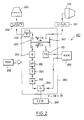
- FIG. 2 is a diagram of the means of calculation of the cinemometric device of FIG. 1a.
- FIG. 1a represents, on a block diagram, a cinemometric device intended to measure the absolute speed V of a vehicle 100 to be checked.
- This device comprises, on board a control vehicle 200, a first kinemometer 210 with Doppler effect for measuring the reference speed V R of said control vehicle 200.
- This cinemometer 210 is, for example, and as shown in FIG. 1b, placed in the control vehicle so as to be able to measure r the speed V R by reverse Doppler effect with respect to the movement of the ground.
- the first speedometer must be installed in a location on the control vehicle that is sufficiently discreet to avoid being spotted.
- a second Doppler effect cinemometer 220 is provided for measuring the relative speed dV of the vehicle 100 to be checked with respect to the control vehicle 200.
- the second cinemometer 220 is mobile and not fixed, the latter operates in a manner completely analogous to the cinemometer described in French patent application No. 87 12787 on behalf of the Applicant, which is included by reference to this application.
- the second cinemometer 220 is installed on the rear shelf of the control vehicle 200 and, like the first cinemometer 210, emits a millimeter wave beam, 12.5 mm in length d wave for example.
- the measurement beam 240 from the second kinemometer is centered around a direction ⁇ making an angle ⁇ with the axis of the control vehicle 200.
- the width of the beam 240 is of the order of 10 °.
- These calculation means 230 essentially comprise two channels.
- a first channel relates to the signal coming from the first cinemometer 210.
- the millimeter wave emitted by said first cinemometer is reflected by the ground and returned to the first cinemometer with a frequency offset, called Doppler frequency, directly proportional to the reference speed V R.
- the analog signal corresponding to the reflected wave is first digitized by a first digital processing unit 231 before being sent to a microprocessor 280.
- said microprocessor 280 On a second channel, said microprocessor 280 also receives a Doppler signal, digitized by a second digital processing unit 232, and corresponding to the millimeter wave reflected by the vehicle 100 to be checked.
- the message supplied by said second digital processing unit 232 comprises 16 bits, one of which is said to be "direction", giving the sign of the relative speed dV recorded by the second speedometer 220.
- the direction bit is detected by means 233 which controls a logical means represented in a completely symbolic way by the coupled switches 241-242.
- the means referred to in the memory are essentially constituted by memories and by software executed by the microprocessor 280, even if they can be replaced by wired logic circuits. These various softwares will not be described in detail since they call upon quite conventional programming techniques within the reach of those skilled in the art. Schematically, the software used is stored in the read-only memory 260.
- the signal direction bit becomes positive and the detection means 233 switches the logic circuit 241-242 to the position where the switch 241 is open, thus suspending the calculation. of the reference speed V R , and where the switch 242 is closed.
- the calculation of the relative speed dV is then carried out by the calculation means 252.
- the 16-bit signal supplied by the second digital processing unit 232 comprises a so-called "quality" bit which makes it possible to validate or not speed measurement.
- a means 253 for controlling the value of said quality bit transmits the signal to means 252 for calculating the relative speed dV if the quality bit is equal to 1.
- the cinemometric device has the particularity of operating at a clock frequency equal to the Doppler frequency.
- the distance ⁇ l between two measurements can be 11 mm, this mistletoe for a beam crossing of 3 m gives approximately 270 measurement points.
- the calculation means 230 comprise means 254 of discrimination which eliminate from the measurement of the successive values of the relative speed dV whose difference is greater at a given threshold S. This characteristic constitutes a significant advantage compared to known tachometric devices which have a response time which is much too long for such an arrangement to be envisaged.
- a training facility 255 averages dV of all the values of the relative speed dV after validation and discrimination. This average is then added to the last value of the reference speed V R stored in the RAM 270 by an adder means 256 which provides the absolute speed V sought, the value of which is displayed on a display device, for example with liquid crystal .
- the means 233 After leaving the vehicle to be checked from the measurement zone, the means 233 again detects a relative speed of negative sign.
- the logic means 241 -242 then switches to the position blocking the measurement of the relative speed dV and allowing the calculation of the reference speed V R to be resumed.
- the second cinemometer comprises at least one passive, infrared and / or acoustic sensor, not shown in FIG. means for switching on / off of said second speedometer.
- This passive sensor and its mode of operation is described in great detail in French patent application No. 87 12787.
- the speed measuring device object of the invention, can also operate when stopped, that is to say at reference speed V R zero.
- the speed V of the vehicle to be checked sought is then equal to the relative speed dV measured by the second speedometer.
Landscapes
- Engineering & Computer Science (AREA)
- Radar, Positioning & Navigation (AREA)
- Remote Sensing (AREA)
- Physics & Mathematics (AREA)
- Computer Networks & Wireless Communication (AREA)
- General Physics & Mathematics (AREA)
- Electromagnetism (AREA)
- Radar Systems Or Details Thereof (AREA)
- Traffic Control Systems (AREA)
- Optical Radar Systems And Details Thereof (AREA)
Applications Claiming Priority (2)
| Application Number | Priority Date | Filing Date | Title |
|---|---|---|---|
| FR9004843A FR2661004B1 (fr) | 1990-04-13 | 1990-04-13 | Dispositif cinemometrique embarque. |
| FR9004843 | 1990-04-13 |
Publications (2)
| Publication Number | Publication Date |
|---|---|
| EP0452221A1 true EP0452221A1 (de) | 1991-10-16 |
| EP0452221B1 EP0452221B1 (de) | 1995-05-31 |
Family
ID=9395791
Family Applications (1)
| Application Number | Title | Priority Date | Filing Date |
|---|---|---|---|
| EP19910400975 Expired - Lifetime EP0452221B1 (de) | 1990-04-13 | 1991-04-11 | Bordseitiger Geschwindigkeitsmesser |
Country Status (3)
| Country | Link |
|---|---|
| EP (1) | EP0452221B1 (de) |
| DE (1) | DE69110079T2 (de) |
| FR (1) | FR2661004B1 (de) |
Families Citing this family (1)
| Publication number | Priority date | Publication date | Assignee | Title |
|---|---|---|---|---|
| DE102018206963B3 (de) | 2018-05-04 | 2019-04-25 | Audi Ag | Verfahren zur Ermittlung einer absoluten Geschwindigkeit eines weiteren Verkehrsteilnehmers und Kraftfahrzeug |
Citations (3)
| Publication number | Priority date | Publication date | Assignee | Title |
|---|---|---|---|---|
| US3118139A (en) * | 1959-11-25 | 1964-01-14 | Specialties Dev Corp | Speed measuring apparatus |
| GB2004158A (en) * | 1977-09-12 | 1979-03-21 | Nissan Motor | Radar system for detecting approaching vehicles from behind |
| US4335382A (en) * | 1980-03-10 | 1982-06-15 | Decatur Electronics, Inc. | Traffic radar system |
-
1990
- 1990-04-13 FR FR9004843A patent/FR2661004B1/fr not_active Expired - Lifetime
-
1991
- 1991-04-11 EP EP19910400975 patent/EP0452221B1/de not_active Expired - Lifetime
- 1991-04-11 DE DE1991610079 patent/DE69110079T2/de not_active Expired - Fee Related
Patent Citations (3)
| Publication number | Priority date | Publication date | Assignee | Title |
|---|---|---|---|---|
| US3118139A (en) * | 1959-11-25 | 1964-01-14 | Specialties Dev Corp | Speed measuring apparatus |
| GB2004158A (en) * | 1977-09-12 | 1979-03-21 | Nissan Motor | Radar system for detecting approaching vehicles from behind |
| US4335382A (en) * | 1980-03-10 | 1982-06-15 | Decatur Electronics, Inc. | Traffic radar system |
Also Published As
| Publication number | Publication date |
|---|---|
| EP0452221B1 (de) | 1995-05-31 |
| FR2661004B1 (fr) | 1992-08-07 |
| DE69110079T2 (de) | 1996-02-15 |
| FR2661004A1 (fr) | 1991-10-18 |
| DE69110079D1 (de) | 1995-07-06 |
Similar Documents
| Publication | Publication Date | Title |
|---|---|---|
| FR2753289A1 (fr) | Procede et dispositif pour detecter automatiquement le sens de la circulation dans un trafic automobile | |
| FR2731515A1 (fr) | Dispositif pour determiner la distance d'un vehicule par rapport a un marquage lateral de la chaussee | |
| FR2978946B1 (fr) | Procede et dispositif d'avertissement de vitesse, notamment de pre-avertissement de courbe pour des vehicules automobiles | |
| FR2961774A1 (fr) | Procede d'avertissement d'un conducteur de risques de collision | |
| FR2473726A1 (fr) | Procede et dispositif pour determiner l'allure de variation de la vitesse de deplacement d'un objet en mouvement | |
| FR2969098A1 (fr) | Procede et dispositif d'assistance du conducteur d'un vehicule | |
| FR2713808A1 (fr) | Dispositif d'anticollision, notamment pour véhicules automobiles. | |
| FR3056804A1 (fr) | Dispositif d'aide a la conduite d'un vehicule par determination et affichage de la distance de freinage dudit vehicule | |
| FR3065191A1 (fr) | Dispositif de signalisation lumineuse d'un changement de voie pour vehicule automobile | |
| FR2902909A1 (fr) | Procede de determination de limites de roulage d'un vehicule | |
| FR3051757A1 (fr) | Dispositif de suivi des habitudes de conduite d'un conducteur d'un vehicule de transport et procede correspondant | |
| EP3947077A1 (de) | Verfahren zur steuerung der positionierung eines kraftfahrzeuges auf einer verkehrsspur | |
| EP4028299B1 (de) | Feststellung von fehlerhaftem radverhalten in einem fahrenden fahrzeug | |
| EP0452221B1 (de) | Bordseitiger Geschwindigkeitsmesser | |
| CA2434550C (fr) | Procede et dispositif d'aide a la conduite d'un vehicule roulant sur le sol | |
| CA3078330A1 (fr) | Dispositif electronique de communication, appareil de surveillance, installation de supervision, procede de communication et programme d'ordinateur associes | |
| EP0234965B1 (de) | Vorrichtung zur Ermittlung der Oberflächenbeschaffenheit von Materialien | |
| FR2987325A1 (fr) | Procede de detection d'obstacles mobiles dans l'angle mort d'un vehicule automobile | |
| EP0477092A1 (de) | Entfernungsmessverfahren zur Messung von kurzen Abständen | |
| EP1007976A1 (de) | Verfahren zum messen der geschwindigkeit eines fahrzeuges | |
| EP3472015B1 (de) | Verfahren zur bestimmung einer referenzfahrklasse | |
| FR3101044A1 (fr) | Procédé d’aide à la conduite avec détermination d’une distance de sécurité multi-cibles. | |
| EP1331621B1 (de) | Verfahren zum Überwachen des Umfeldes eines Fahrzeugs | |
| EP4136475B1 (de) | Verfahren zur erkennung einer verkehrsstausituation in einem kraftfahrzeug | |
| EP1387184A1 (de) | Spurabdriftdetektionsgerät |
Legal Events
| Date | Code | Title | Description |
|---|---|---|---|
| PUAI | Public reference made under article 153(3) epc to a published international application that has entered the european phase |
Free format text: ORIGINAL CODE: 0009012 |
|
| AK | Designated contracting states |
Kind code of ref document: A1 Designated state(s): BE CH DE IT LI |
|
| 17P | Request for examination filed |
Effective date: 19920406 |
|
| 17Q | First examination report despatched |
Effective date: 19940214 |
|
| GRAA | (expected) grant |
Free format text: ORIGINAL CODE: 0009210 |
|
| AK | Designated contracting states |
Kind code of ref document: B1 Designated state(s): BE CH DE IT LI |
|
| REF | Corresponds to: |
Ref document number: 69110079 Country of ref document: DE Date of ref document: 19950706 |
|
| ITF | It: translation for a ep patent filed | ||
| PLBE | No opposition filed within time limit |
Free format text: ORIGINAL CODE: 0009261 |
|
| STAA | Information on the status of an ep patent application or granted ep patent |
Free format text: STATUS: NO OPPOSITION FILED WITHIN TIME LIMIT |
|
| 26N | No opposition filed | ||
| PGFP | Annual fee paid to national office [announced via postgrant information from national office to epo] |
Ref country code: DE Payment date: 20010514 Year of fee payment: 11 |
|
| PGFP | Annual fee paid to national office [announced via postgrant information from national office to epo] |
Ref country code: CH Payment date: 20010516 Year of fee payment: 11 |
|
| PGFP | Annual fee paid to national office [announced via postgrant information from national office to epo] |
Ref country code: BE Payment date: 20010611 Year of fee payment: 11 |
|
| PG25 | Lapsed in a contracting state [announced via postgrant information from national office to epo] |
Ref country code: LI Free format text: LAPSE BECAUSE OF NON-PAYMENT OF DUE FEES Effective date: 20020430 Ref country code: CH Free format text: LAPSE BECAUSE OF NON-PAYMENT OF DUE FEES Effective date: 20020430 Ref country code: BE Free format text: LAPSE BECAUSE OF NON-PAYMENT OF DUE FEES Effective date: 20020430 |
|
| PG25 | Lapsed in a contracting state [announced via postgrant information from national office to epo] |
Ref country code: DE Free format text: LAPSE BECAUSE OF NON-PAYMENT OF DUE FEES Effective date: 20021101 |
|
| REG | Reference to a national code |
Ref country code: CH Ref legal event code: PL |
|
| PG25 | Lapsed in a contracting state [announced via postgrant information from national office to epo] |
Ref country code: IT Free format text: LAPSE BECAUSE OF NON-PAYMENT OF DUE FEES Effective date: 20050411 |