EP0452228A1 - Schutzrelais für ein Mittelspannungsnetz - Google Patents
Schutzrelais für ein Mittelspannungsnetz Download PDFInfo
- Publication number
- EP0452228A1 EP0452228A1 EP91420100A EP91420100A EP0452228A1 EP 0452228 A1 EP0452228 A1 EP 0452228A1 EP 91420100 A EP91420100 A EP 91420100A EP 91420100 A EP91420100 A EP 91420100A EP 0452228 A1 EP0452228 A1 EP 0452228A1
- Authority
- EP
- European Patent Office
- Prior art keywords
- relay according
- transformer
- input
- relay
- primary winding
- Prior art date
- Legal status (The legal status is an assumption and is not a legal conclusion. Google has not performed a legal analysis and makes no representation as to the accuracy of the status listed.)
- Ceased
Links
- 230000001012 protector Effects 0.000 title abstract 2
- 238000004804 winding Methods 0.000 claims abstract description 24
- 239000004020 conductor Substances 0.000 claims description 13
- 239000000696 magnetic material Substances 0.000 claims description 6
- 239000002184 metal Substances 0.000 claims description 5
- 229910052751 metal Inorganic materials 0.000 claims description 5
- 238000007493 shaping process Methods 0.000 description 2
- RYGMFSIKBFXOCR-UHFFFAOYSA-N Copper Chemical compound [Cu] RYGMFSIKBFXOCR-UHFFFAOYSA-N 0.000 description 1
- 229910052802 copper Inorganic materials 0.000 description 1
- 239000010949 copper Substances 0.000 description 1
- 230000008878 coupling Effects 0.000 description 1
- 238000010168 coupling process Methods 0.000 description 1
- 238000005859 coupling reaction Methods 0.000 description 1
- 230000005684 electric field Effects 0.000 description 1
- 230000005672 electromagnetic field Effects 0.000 description 1
- 239000003973 paint Substances 0.000 description 1
- 238000010079 rubber tapping Methods 0.000 description 1
Images

Classifications
-
- H—ELECTRICITY
- H02—GENERATION; CONVERSION OR DISTRIBUTION OF ELECTRIC POWER
- H02H—EMERGENCY PROTECTIVE CIRCUIT ARRANGEMENTS
- H02H1/00—Details of emergency protective circuit arrangements
Definitions
- the invention relates to a protection relay for a medium-voltage electrical network, placed in a housing comprising at least one conductive part, and comprising inputs to which analog input signals representative of electrical parameters of said network are applied, a set electronics for processing input signals and a reducing transformer, associated with each input, comprising a primary winding connected to said input and a secondary winding connected to the electronic processing assembly.
- Electronic circuits and more particularly digital electronic circuits, are very sensitive to variations in electromagnetic fields produced by the medium voltage environment.
- the invention aims to limit these disturbances with simple, inexpensive and space-saving means.
- this object is achieved by the fact that the primary winding of a reducing transformer, consisting of a conductor connecting two terminals of the associated input, is shielded by a non-magnetic material, said shield being connected to its two ends to a conductive part of the housing, grounded.
- This shielding preferably consisting of a braid of non-magnetic material, constitutes a Faraday cage of reduced bulk and very inexpensive, making it possible to limit the electromagnetic disturbances, by capacitive coupling, as well as disturbances due to the low frequency magnetic field or to the low frequency electric field likely to affect the electronic processing unit.
- said conductive part for example metallic, consists of an external wall of the housing on which said inlets are arranged.
- the primary windings of all the reducing transformers of the relay can be shielded. However, it is possible, while obtaining satisfactory results, to limit itself to the shielding of the primary windings of the current transformers.
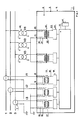
- FIG. 1 schematically represents a relay according to the invention.
- Figures 2 and 3 respectively illustrate an input of a current signal and an input of a voltage signal.
- a relay intended to protect a three-phase medium-voltage electrical network comprising three phase conductors 1, 2 and 3, comprises an electronic trip device 4.
- the trigger 4 is arranged in a housing 5, an external wall 6 of which is conductive, is earthed.
- the wall 6 is a metal wall but may consist of a plastic wall loaded with conductive material or covered with a metallic paint.
- Analog input signals are applied to inputs of the release.
- a current input signal, I1, I2 or I3, is conventionally obtained by means of a current transformer 7 whose primary winding is constituted by the conductor considered and whose secondary winding is connected to ground by a end and a first terminal 8 of the input associated by the other end. The second terminals 9 of the current inputs are all connected to ground.
- a voltage input signal, V1, V2 or V3, is obtained by means of a voltage transformer 26 whose winding is connected at one end to the conductor considered and at the other end to ground. The secondary of the transformer 26 is connected at one end to the terminals 10 for V1 and V3 and to the terminals 11 for V2, the other end of the secondary of the transformer 26 being connected to ground.
- the input terminals 8, 9, 10, 11 are preferably arranged on the external metal wall 6 of the housing.
- the input currents and voltages are too high to be processed directly by the electronic processing unit 12 of the trip device.
- the current signals generally have an intensity of the order of a few amps, typically 1 to 5A, while the voltage signals can be of the order of a hundred volts.
- a reducing transformer is therefore interposed between each input and the electronic processing unit.
- the two ends of the shield are connected to the metal wall 6, grounded by any suitable means, for example by means of a self-tapping screw or a screw-nut system.
- Figure 2 illustrates in more detail the shielded conductor 15,16, passing through the O-ring core 17 of the current transformer.
- the secondary winding 18 of the transformer 13 is connected to a shaping circuit 19, the output of which is connected to an input of the electronic processing assembly 12.
- the primary 15 of the current transformer 13 forms a single turn passing through the torus 17.
- the primary 15 can comprise several turns.
- the primary winding 20 of a voltage reducing transformer 14, connected to terminals 10 and 11, is shielded by a shield 21 made of non-magnetic material.
- a shield 21 made of non-magnetic material.
- the shield 21 is connected, by any suitable means, on the one hand to the metal wall 6 and on the other hand to an insulating electrical screen 22, grounded, separating the primary windings 20 and secondary 23.
- the relative dimensions of the shielded part of the conductor 20 and the unshielded part must be such that the shielding nevertheless constitutes a Faraday cage.
- this type of shielding is sufficient in practice for a voltage transformer 14 in which the transverse dimension covered with turns is of the order of a centimeter, while the length of the conductor going from the input terminals 10 or 11, the part constituting the turns is of the order of ten centimeters.
- the secondary winding 23 of the transformer 14 is connected to the electronic processing unit 12 via a shaping circuit 24.
- the shielding according to the invention is more particularly suitable in the case of a trip device 4 whose electronic processing assembly includes a microprocessor, the analog input signals being multiplexed then transformed into digital signals before being processed by the microprocessor .
- the electronic processing unit 12 performs in particular protection functions and can transmit triggering and closing commands to a triggering relay shown diagrammatically at 25 in FIG. 1.
Landscapes
- Emergency Protection Circuit Devices (AREA)
Applications Claiming Priority (2)
| Application Number | Priority Date | Filing Date | Title |
|---|---|---|---|
| FR9004915 | 1990-04-11 | ||
| FR9004915A FR2661052B1 (fr) | 1990-04-11 | 1990-04-11 | Relais de protection d'un reseau electrique moyenne tension. |
Publications (1)
| Publication Number | Publication Date |
|---|---|
| EP0452228A1 true EP0452228A1 (de) | 1991-10-16 |
Family
ID=9395829
Family Applications (1)
| Application Number | Title | Priority Date | Filing Date |
|---|---|---|---|
| EP91420100A Ceased EP0452228A1 (de) | 1990-04-11 | 1991-03-26 | Schutzrelais für ein Mittelspannungsnetz |
Country Status (3)
| Country | Link |
|---|---|
| EP (1) | EP0452228A1 (de) |
| CA (1) | CA2039550A1 (de) |
| FR (1) | FR2661052B1 (de) |
Cited By (2)
| Publication number | Priority date | Publication date | Assignee | Title |
|---|---|---|---|---|
| EP0722092A1 (de) * | 1995-01-16 | 1996-07-17 | Schneider Electric Sa | Testanordnung für ein mit amagnetischen Fühlern verbundenes Sicherheitsrelais |
| EP2365618A1 (de) * | 2010-03-08 | 2011-09-14 | ABB Research Ltd. | Spannungsreduzierende Wechselstromversorgungseinheit für Netzschutzgeräte am Mittelspannungsnetz |
Citations (4)
| Publication number | Priority date | Publication date | Assignee | Title |
|---|---|---|---|---|
| DE850488C (de) * | 1951-06-19 | 1952-09-25 | Utina Elektrowerk Gmbh | Elektroweidezaungeraet mit Hochfrequenz-Entstoerung |
| DE1291413B (de) * | 1962-11-01 | 1969-03-27 | Hitachi Ltd | Transformator |
| DE2514583A1 (de) * | 1974-04-12 | 1975-10-30 | Siemens Ag | Abschirmgehaeuse |
| EP0313739A2 (de) * | 1987-10-30 | 1989-05-03 | VDO Adolf Schindling AG | Kombinationsinstrument für Kraftfahrzeuge |
-
1990
- 1990-04-11 FR FR9004915A patent/FR2661052B1/fr not_active Expired - Fee Related
-
1991
- 1991-03-26 EP EP91420100A patent/EP0452228A1/de not_active Ceased
- 1991-04-02 CA CA 2039550 patent/CA2039550A1/en not_active Abandoned
Patent Citations (4)
| Publication number | Priority date | Publication date | Assignee | Title |
|---|---|---|---|---|
| DE850488C (de) * | 1951-06-19 | 1952-09-25 | Utina Elektrowerk Gmbh | Elektroweidezaungeraet mit Hochfrequenz-Entstoerung |
| DE1291413B (de) * | 1962-11-01 | 1969-03-27 | Hitachi Ltd | Transformator |
| DE2514583A1 (de) * | 1974-04-12 | 1975-10-30 | Siemens Ag | Abschirmgehaeuse |
| EP0313739A2 (de) * | 1987-10-30 | 1989-05-03 | VDO Adolf Schindling AG | Kombinationsinstrument für Kraftfahrzeuge |
Non-Patent Citations (2)
| Title |
|---|
| DOCUMENTATION DES PRODUITS SIEMENS, 1972, pages 1-13, DE; "Ueberstromzeitschutzsystem" * |
| ELEKTRONIK, vol. 23, no. 4, 1974, page 130, M}nchen, DE; R. BOLL: "Flexible magnetische Abschirmschl{uche" * |
Cited By (3)
| Publication number | Priority date | Publication date | Assignee | Title |
|---|---|---|---|---|
| EP0722092A1 (de) * | 1995-01-16 | 1996-07-17 | Schneider Electric Sa | Testanordnung für ein mit amagnetischen Fühlern verbundenes Sicherheitsrelais |
| FR2729473A1 (fr) * | 1995-01-16 | 1996-07-19 | Schneider Electric Sa | Dispositif d'essai d'un relais de protection connecte a des capteurs amagnetiques |
| EP2365618A1 (de) * | 2010-03-08 | 2011-09-14 | ABB Research Ltd. | Spannungsreduzierende Wechselstromversorgungseinheit für Netzschutzgeräte am Mittelspannungsnetz |
Also Published As
| Publication number | Publication date |
|---|---|
| FR2661052B1 (fr) | 1995-04-14 |
| CA2039550A1 (en) | 1991-10-12 |
| FR2661052A1 (fr) | 1991-10-18 |
Similar Documents
| Publication | Publication Date | Title |
|---|---|---|
| US4290663A (en) | In high frequency screening of electrical systems | |
| CN100392937C (zh) | 具有冲击保护的同轴终端 | |
| EP1736784A1 (de) | Gerät zur Fehlerstrommessung, Auslösemodul und Schaltvorrichtung | |
| US6950294B2 (en) | Surge protection filter and lightning conductor system | |
| CN1460182A (zh) | 用于高电压的绝缘连接并具有电压和电流检测器的模块化系统 | |
| FR2737922A1 (fr) | Capteur de courant et appareil electrique le comportant | |
| EP0452228A1 (de) | Schutzrelais für ein Mittelspannungsnetz | |
| US656680A (en) | System of electrical distribution. | |
| FR2723486A1 (fr) | Detecteur de tension unipolaire, notamment pour ligne electrique aerienne | |
| US20050077994A1 (en) | Encapsulated fuse with corona shield | |
| FR2709593A1 (fr) | Traversée de courant multifonctionnelle. | |
| EP1684394B1 (de) | Mittelspannung/Niederspannung - Transformatorenstation | |
| FR2703506A1 (fr) | Disjoncteur comportant un dispositif de raccordement de déclencheurs. | |
| EP0559580B1 (de) | Verbindungsblock für Mittelspannungsrelais mit Stromsensoren | |
| EP1659413B1 (de) | Trenntransformator | |
| CA2214024A1 (fr) | Conducteur electrique protege contre les perturbations electromagnetiques depassant un seuil | |
| EP0722092A1 (de) | Testanordnung für ein mit amagnetischen Fühlern verbundenes Sicherheitsrelais | |
| CH689765A5 (fr) | Procédé et dispositif pour la mesure de composantes dynamiques d'un courant électrique en présence d'une composante continue. | |
| FR2554284A1 (fr) | Procede de protection contre la foudre d'installations electriques ou electroniques | |
| JP2860002B2 (ja) | 高周波部分放電センサ | |
| BE1005762A3 (nl) | Stekker voor uk landen met een tegen stoorsignalen niet beschermd tweeaderig snoer. | |
| US2460553A (en) | Electric current theft prevention means | |
| FR2586137A1 (fr) | Telecommande d'ouverture d'un dispositif de protection differentielle, notamment d'un disjoncteur differentiel de branchement | |
| FR3069718B1 (fr) | Appareil de protection electrique differentielle | |
| JPH11299022A (ja) | ガス絶縁開閉装置内の変流器の試験装置 |
Legal Events
| Date | Code | Title | Description |
|---|---|---|---|
| PUAI | Public reference made under article 153(3) epc to a published international application that has entered the european phase |
Free format text: ORIGINAL CODE: 0009012 |
|
| AK | Designated contracting states |
Kind code of ref document: A1 Designated state(s): BE CH DE ES GB IT LI SE |
|
| 17P | Request for examination filed |
Effective date: 19920316 |
|
| 17Q | First examination report despatched |
Effective date: 19940407 |
|
| STAA | Information on the status of an ep patent application or granted ep patent |
Free format text: STATUS: THE APPLICATION HAS BEEN REFUSED |
|
| 18R | Application refused |
Effective date: 19950306 |