EP0452230A1 - Antriebsmechanismus für Schutzschalter - Google Patents
Antriebsmechanismus für Schutzschalter Download PDFInfo
- Publication number
- EP0452230A1 EP0452230A1 EP91420108A EP91420108A EP0452230A1 EP 0452230 A1 EP0452230 A1 EP 0452230A1 EP 91420108 A EP91420108 A EP 91420108A EP 91420108 A EP91420108 A EP 91420108A EP 0452230 A1 EP0452230 A1 EP 0452230A1
- Authority
- EP
- European Patent Office
- Prior art keywords
- indicator
- lever
- arm
- control mechanism
- nose
- Prior art date
- Legal status (The legal status is an assumption and is not a legal conclusion. Google has not performed a legal analysis and makes no representation as to the accuracy of the status listed.)
- Granted
Links
- 238000003466 welding Methods 0.000 claims abstract description 8
- 230000011664 signaling Effects 0.000 claims abstract description 6
- 238000005476 soldering Methods 0.000 claims description 8
- 230000005540 biological transmission Effects 0.000 claims description 4
- 210000003127 knee Anatomy 0.000 claims 1
- 230000000903 blocking effect Effects 0.000 description 2
- 230000007935 neutral effect Effects 0.000 description 2
- 238000000926 separation method Methods 0.000 description 2
- 230000001154 acute effect Effects 0.000 description 1
- 230000001419 dependent effect Effects 0.000 description 1
- 238000006073 displacement reaction Methods 0.000 description 1
Images


Classifications
-
- H—ELECTRICITY
- H01—ELECTRIC ELEMENTS
- H01H—ELECTRIC SWITCHES; RELAYS; SELECTORS; EMERGENCY PROTECTIVE DEVICES
- H01H71/00—Details of the protective switches or relays covered by groups H01H73/00 - H01H83/00
- H01H71/10—Operating or release mechanisms
- H01H71/50—Manual reset mechanisms which may be also used for manual release
- H01H71/501—Means for breaking welded contacts; Indicating contact welding or other malfunction of the circuit breaker
-
- H—ELECTRICITY
- H01—ELECTRIC ELEMENTS
- H01H—ELECTRIC SWITCHES; RELAYS; SELECTORS; EMERGENCY PROTECTIVE DEVICES
- H01H71/00—Details of the protective switches or relays covered by groups H01H73/00 - H01H83/00
- H01H71/04—Means for indicating condition of the switching device
-
- H—ELECTRICITY
- H01—ELECTRIC ELEMENTS
- H01H—ELECTRIC SWITCHES; RELAYS; SELECTORS; EMERGENCY PROTECTIVE DEVICES
- H01H71/00—Details of the protective switches or relays covered by groups H01H73/00 - H01H83/00
- H01H71/10—Operating or release mechanisms
- H01H71/50—Manual reset mechanisms which may be also used for manual release
- H01H71/52—Manual reset mechanisms which may be also used for manual release actuated by lever
- H01H71/526—Manual reset mechanisms which may be also used for manual release actuated by lever the lever forming a toggle linkage with a second lever, the free end of which is directly and releasably engageable with a contact structure
Definitions
- the invention relates to a control mechanism for an electrical circuit breaker with an insulating housing enclosing a pair of fixed and movable contacts, said movable contact being carried by a contact arm actuated by the mechanism, which comprises a lever pivotally mounted on an axis. and movable in an orifice of the case between two extreme positions F for closing and O for opening, a transmission link coupled to the lever to form a toggle joint, a breakable mechanical connection between the link and a support lever for the contact arm, a trip lever for locking and unlocking the mechanical connection, and a mechanical indicator of the state of the circuit breaker having an indicator light capable of occupying an active position visible from the outside in the position O of opening of the lever.
- the object of the invention is to improve the reliability of a mechanical indicator of the state of a circuit breaker by making it insensitive to the test force exerted on the handle.
- the mechanism according to the invention is characterized in that the indicator comprises a bistable lever mounted for free rotation on the axis of the lever, and cooperating with a nose of the lever support intended to lock the indicator and make it invisible in a stable inactive position, when the lever is actuated from the closed F position to the open O position in the event of soldering of the contacts.
- the bistable arrangement of the indicator allows the open or closed state of the contacts to be recognized in complete safety.
- the indicator is only visible in the active position, corresponding to the opening position of the lever after separation of the contacts.
- the indicator is invisible in the inactive position when the contacts are closed normally or by accidental welding.
- the indicator is insensitive to the test force exerted on the lever, given its cooperation with the support arm of the contact arm.
- the indicator lever includes a first signaling arm on which the indicator is arranged, and a second control arm cooperating with the nose, the two arms being angularly offset from each other by a predetermined angle, centered on the axis of the joystick.
- the indicator is returned to the inactive position by means of the action of the lever on the first arm.
- the mechanism is equipped with a mechanical device for locking the handle in an intermediate position S in the event of contact welding. This results in a fully visible cut-off function with contact position indicator.
- the mechanism 10 is housed in the insulating case 12 of the circuit breaker, and is intended to actuate a movable contact arm 13 having a contact piece 14 cooperating with a fixed contact 16.
- the mechanism 10 comprises a lever 18 pivotally coupled to a transmission link 20 to form a toggle switch 22, and a plate 24 mounted with limited rotation on a pivot 26 between a closed position and an open position of the contacts 14, 16.
- On the pivot 26 is threaded a support lever 28 insulating the arm from this contact 13.
- a mechanical connection 30 with a breakable connecting rod is formed by a second toggle joint having a hooking hook 32 pivotally mounted on an axis 34 of the plate 24 while being articulated to the connecting rod 20 of transmission.
- a trigger lever 36 is mounted on an axis 38 of the plate 24 and cooperates with the retaining spout of the latching hook 32 to ensure the locking and unlocking of the mechanical connection 30.
- the lever 18 projects from an orifice 40 in the housing 12 and is pivotally mounted on an axis 42 between two extreme positions F and 0 corresponding respectively to the closing and the opening of the contacts 14,16.
- the mechanism 10 is provided with a mechanical indicator 50 formed by a bistable lever (fig. 1 to 4) mounted for free rotation on the axis 42 of the lever 18.
- a return spring (not shown) requests the indicator 50 anticlockwise corresponding to the direction of opening of the lever 18.
- the indicator 50 comprises a first signaling arm 52 whose side face carries a colored light 54 and a second arm 54 of control equipped with a step 55 capable of cooperating with a nose 56 of the support lever 28.
- the first and second arms 52, 54 are angularly offset from each other by an acute angle centered on the axis 42 of the lever 18.
- the two opposite flanks of the second arm 54 come into engagement with a pair of end-of-travel stops 58.60, secured to the housing 12 to delimit the angular travel of the indicator 50.
- the indicator 50 is in a first stable inactive position, in which the indicator 54 of the first arm 52 remains invisible from the outside.
- the contact arm 13 and its support lever 28 remain fixed, and the nose 56 blocks the step 55 of the first arm 54 to maintain the indicator 50 in the first stable position, when the operator attempts to actuate the lever 18 towards the open position.
- the indicator 54 remains invisible when the lever 18 is between the intermediate position S and the open position O.
- the lever 18 In the event of non-welding of the contacts 14, 16 following a manual opening or an automatic triggering of the mechanism 10, the lever 18 is moved to the left position 0, and the nose 56 of the support lever 28 no longer interferes with the step 55 of the first arm 54.
- the absence of blocking of the nose 56 on the second arm 54 and of the boss 62 of the lever 18 on the first arm 52 authorizes the pivoting of the indicator anticlockwise 50 to the second stable active position (fig. 4) under the action of the return spring.
- the second arm 54 bears against the second stop 60, and the appearance of the indicator 54 outside the orifice 40 signals the effective opening of the contacts 14, 16.
- the reclosing of the circuit breaker is effected by displacement of the handle 18 from position 0 to position F.
- the boss 62 of the handle 18 pushes the first arm 52 in the direction of the needles d 'a watch, and automatically returns the indicator 50 to the first stable position against the return force of the spring.
- the indicator 54 can occupy two stable positions, one of which corresponding to the visible state indicates the separation of the contacts 14,16, and the other of which corresponding to the invisible state, signals the normal or welded closure of the contacts 14.16.
- the display function is performed by a separate part of the handle 18. By its cooperation with the nose 56 of the support lever 28, the bistable indicator 50 is insensitive to the test force exerted on the handle 18. The indicator 50 will remain in the first inactive position if the lever 18 is forced towards the open position O in the event of soldering of the contacts.
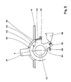
- the variant of the indicator 150 illustrated in FIGS. 5 to 7 uses an additional drive spring 66 arranged between the nose 56 of the support lever 28 and the second arm 154.
- the spring 66 is shaped as a twist pin positioned on a stud 68 of the housing 12.
- the ends of the spring 66 can move in oblong openings 70, 72 made respectively in the second arm 154, and the nose 56.
- the step 55 is eliminated, and the rest of the mechanism is identical to that of FIGS. 1 to 4.
- the operation of the indicator 150 in FIGS. 5 to 7 is similar to that described above, with the difference that the spring 66 plays the role of stroke amplifier, particularly recommended in a single-pole and neutral circuit breaker, in which the two arms of phase and neutral contact are slightly angularly offset.
- the indicator 250 comprises a first signaling arm 252, the indicator 54 of which is shaped in a circular sector having a diameter close to that of the base 80 of the lever 18.
- the diameter of the second control arm 254 with step 255 is greater than that of the first arm 252.
- the indicator 54 remains invisible by being blocked in the first inactive position by the action of the nose 56 on the step 255, even when the lever 18 is forced towards the open position O .
- the second arm 254 is in abutment against a stop 86 of the base 80.
- the mechanism 10 is equipped with a device for blocking the lever 18 in the event of welding of the contacts 14, 16.
- the hooking hook 32 is equipped with a protrusion 144 coming into engagement against a stop integral with the housing 12 in the closed-welded state of the contacts 14, 16, to stop the lever 18 in a predetermined intermediate position S, located between the extreme positions F and O.
- the passing of the dead center of the toggle switch 22 makes it stable said intermediate position S of the lever 18.
- the indicator 54 remains invisible in this position.
- the locking of the lever 18 in the position S is effected by the engagement of the protrusion 144 against the stop of the housing 12, which collects the force exerted on the lever 18 in the event of forced actuation.
Landscapes
- Breakers (AREA)
- Keying Circuit Devices (AREA)
- Driving Mechanisms And Operating Circuits Of Arc-Extinguishing High-Tension Switches (AREA)
- Lock And Its Accessories (AREA)
Applications Claiming Priority (2)
| Application Number | Priority Date | Filing Date | Title |
|---|---|---|---|
| FR9004642A FR2660794B1 (fr) | 1990-04-09 | 1990-04-09 | Mecanisme de commande d'un disjoncteur electrique. |
| FR9004642 | 1990-04-09 |
Publications (2)
| Publication Number | Publication Date |
|---|---|
| EP0452230A1 true EP0452230A1 (de) | 1991-10-16 |
| EP0452230B1 EP0452230B1 (de) | 1994-12-07 |
Family
ID=9395658
Family Applications (1)
| Application Number | Title | Priority Date | Filing Date |
|---|---|---|---|
| EP91420108A Expired - Lifetime EP0452230B1 (de) | 1990-04-09 | 1991-03-29 | Antriebsmechanismus für Schutzschalter |
Country Status (5)
| Country | Link |
|---|---|
| EP (1) | EP0452230B1 (de) |
| AT (1) | ATE115329T1 (de) |
| DE (1) | DE69105591T2 (de) |
| ES (1) | ES2067899T3 (de) |
| FR (1) | FR2660794B1 (de) |
Cited By (13)
| Publication number | Priority date | Publication date | Assignee | Title |
|---|---|---|---|---|
| EP0897186A3 (de) * | 1997-08-14 | 1999-08-04 | Siemens Aktiengesellschaft | Schaltmechanismus für einen Schulzschalter |
| DE19919418A1 (de) * | 1999-04-28 | 2000-11-02 | Siemens Ag | Schutzschalter mit Schaltstellungsanzeige |
| US6239395B1 (en) * | 1999-10-14 | 2001-05-29 | General Electric Company | Auxiliary position switch assembly for a circuit breaker |
| EP1111644A1 (de) * | 1999-12-21 | 2001-06-27 | Hager Electro S.A. | Sichereitsvorrichtung für elektrisches Gerät |
| EP1143477A1 (de) * | 2000-04-07 | 2001-10-10 | Hager Electro S.A. | Sicherheitseinrichtung für elektrisches Gerät vom Schutzschalter Typ |
| EP1039499A3 (de) * | 1999-03-23 | 2002-09-11 | General Electric Company | Betätigungshebeleinheit für elektrische Lastschalter |
| FR2859816A1 (fr) * | 2003-09-11 | 2005-03-18 | Legrand Sa | Dispositif de coupure de courant electrique a discrimination complete d'etats |
| US6919785B2 (en) | 2000-05-16 | 2005-07-19 | General Electric Company | Pressure sensitive trip mechanism for a rotary breaker |
| US6995640B2 (en) | 2000-05-16 | 2006-02-07 | General Electric Company | Pressure sensitive trip mechanism for circuit breakers |
| EP2061058A1 (de) | 2007-11-16 | 2009-05-20 | Schneider Electric Industries SAS | Steuervorrichtung für ein elektrisches Unterbrechungsgerät und elektrisches Unterbrechungsgerät, das damit ausgestattet ist |
| FR2931998A1 (fr) * | 2008-06-03 | 2009-12-04 | Schneider Electric Ind Sas | Dispositif de commande d'un appareil de coupure electrique comportant un dispositif de signalisation de la soudure des contacts, et appareil de coupure electrique comportant un tel dispositif |
| CN102426999A (zh) * | 2011-09-13 | 2012-04-25 | 浙江正泰电器股份有限公司 | 模数化断路器的操作机构 |
| US20140070953A1 (en) * | 2012-09-13 | 2014-03-13 | Schneider Electric Industries Sas | Relay and a method for indicating a relay failure |
Families Citing this family (71)
| Publication number | Priority date | Publication date | Assignee | Title |
|---|---|---|---|---|
| AT404647B (de) * | 1996-02-26 | 1999-01-25 | Felten & Guilleaume Ag Oester | Elektrischer schutzschalter |
| IT1292453B1 (it) | 1997-07-02 | 1999-02-08 | Aeg Niederspannungstech Gmbh | Gruppo rotante di contatti per interrutttori di alta portata |
| DE19735408B4 (de) * | 1997-08-14 | 2008-04-10 | Siemens Ag | Schaltmechanismus für einen Schutzschalter |
| DE19819242B4 (de) | 1998-04-29 | 2005-11-10 | Ge Power Controls Polska Sp.Z.O.O. | Thermomagnetischer Leistungsschalter |
| US6114641A (en) | 1998-05-29 | 2000-09-05 | General Electric Company | Rotary contact assembly for high ampere-rated circuit breakers |
| US6087913A (en) | 1998-11-20 | 2000-07-11 | General Electric Company | Circuit breaker mechanism for a rotary contact system |
| US6037555A (en) | 1999-01-05 | 2000-03-14 | General Electric Company | Rotary contact circuit breaker venting arrangement including current transformer |
| US6262872B1 (en) | 1999-06-03 | 2001-07-17 | General Electric Company | Electronic trip unit with user-adjustable sensitivity to current spikes |
| US6268991B1 (en) | 1999-06-25 | 2001-07-31 | General Electric Company | Method and arrangement for customizing electronic circuit interrupters |
| US6218917B1 (en) | 1999-07-02 | 2001-04-17 | General Electric Company | Method and arrangement for calibration of circuit breaker thermal trip unit |
| US6188036B1 (en) | 1999-08-03 | 2001-02-13 | General Electric Company | Bottom vented circuit breaker capable of top down assembly onto equipment |
| US6710988B1 (en) | 1999-08-17 | 2004-03-23 | General Electric Company | Small-sized industrial rated electric motor starter switch unit |
| US6252365B1 (en) | 1999-08-17 | 2001-06-26 | General Electric Company | Breaker/starter with auto-configurable trip unit |
| US6396369B1 (en) | 1999-08-27 | 2002-05-28 | General Electric Company | Rotary contact assembly for high ampere-rated circuit breakers |
| US6175288B1 (en) | 1999-08-27 | 2001-01-16 | General Electric Company | Supplemental trip unit for rotary circuit interrupters |
| US6232570B1 (en) | 1999-09-16 | 2001-05-15 | General Electric Company | Arcing contact arrangement |
| US6326869B1 (en) | 1999-09-23 | 2001-12-04 | General Electric Company | Clapper armature system for a circuit breaker |
| US6229413B1 (en) | 1999-10-19 | 2001-05-08 | General Electric Company | Support of stationary conductors for a circuit breaker |
| US6317018B1 (en) | 1999-10-26 | 2001-11-13 | General Electric Company | Circuit breaker mechanism |
| US6232856B1 (en) | 1999-11-02 | 2001-05-15 | General Electric Company | Magnetic shunt assembly |
| EP1098343B1 (de) | 1999-11-03 | 2005-09-21 | AEG Niederspannungstechnik GmbH & Co. KG | Drehkontaktanordnung für Schutzschalter |
| US6377144B1 (en) | 1999-11-03 | 2002-04-23 | General Electric Company | Molded case circuit breaker base and mid-cover assembly |
| US6300586B1 (en) | 1999-12-09 | 2001-10-09 | General Electric Company | Arc runner retaining feature |
| US6310307B1 (en) | 1999-12-17 | 2001-10-30 | General Electric Company | Circuit breaker rotary contact arm arrangement |
| US6172584B1 (en) | 1999-12-20 | 2001-01-09 | General Electric Company | Circuit breaker accessory reset system |
| US6184761B1 (en) | 1999-12-20 | 2001-02-06 | General Electric Company | Circuit breaker rotary contact arrangement |
| US6215379B1 (en) | 1999-12-23 | 2001-04-10 | General Electric Company | Shunt for indirectly heated bimetallic strip |
| US6281461B1 (en) | 1999-12-27 | 2001-08-28 | General Electric Company | Circuit breaker rotor assembly having arc prevention structure |
| US6346869B1 (en) | 1999-12-28 | 2002-02-12 | General Electric Company | Rating plug for circuit breakers |
| US6211758B1 (en) | 2000-01-11 | 2001-04-03 | General Electric Company | Circuit breaker accessory gap control mechanism |
| US6239677B1 (en) | 2000-02-10 | 2001-05-29 | General Electric Company | Circuit breaker thermal magnetic trip unit |
| US6429759B1 (en) | 2000-02-14 | 2002-08-06 | General Electric Company | Split and angled contacts |
| US6313425B1 (en) | 2000-02-24 | 2001-11-06 | General Electric Company | Cassette assembly with rejection features |
| US6281458B1 (en) | 2000-02-24 | 2001-08-28 | General Electric Company | Circuit breaker auxiliary magnetic trip unit with pressure sensitive release |
| US6204743B1 (en) | 2000-02-29 | 2001-03-20 | General Electric Company | Dual connector strap for a rotary contact circuit breaker |
| US6404314B1 (en) | 2000-02-29 | 2002-06-11 | General Electric Company | Adjustable trip solenoid |
| US6379196B1 (en) | 2000-03-01 | 2002-04-30 | General Electric Company | Terminal connector for a circuit breaker |
| US6346868B1 (en) | 2000-03-01 | 2002-02-12 | General Electric Company | Circuit interrupter operating mechanism |
| US6340925B1 (en) | 2000-03-01 | 2002-01-22 | General Electric Company | Circuit breaker mechanism tripping cam |
| US6448521B1 (en) | 2000-03-01 | 2002-09-10 | General Electric Company | Blocking apparatus for circuit breaker contact structure |
| US6211757B1 (en) | 2000-03-06 | 2001-04-03 | General Electric Company | Fast acting high force trip actuator |
| US6459349B1 (en) | 2000-03-06 | 2002-10-01 | General Electric Company | Circuit breaker comprising a current transformer with a partial air gap |
| US6496347B1 (en) | 2000-03-08 | 2002-12-17 | General Electric Company | System and method for optimization of a circuit breaker mechanism |
| US6429659B1 (en) | 2000-03-09 | 2002-08-06 | General Electric Company | Connection tester for an electronic trip unit |
| US6218919B1 (en) | 2000-03-15 | 2001-04-17 | General Electric Company | Circuit breaker latch mechanism with decreased trip time |
| US6366188B1 (en) | 2000-03-15 | 2002-04-02 | General Electric Company | Accessory and recess identification system for circuit breakers |
| US6232859B1 (en) | 2000-03-15 | 2001-05-15 | General Electric Company | Auxiliary switch mounting configuration for use in a molded case circuit breaker |
| US6459059B1 (en) | 2000-03-16 | 2002-10-01 | General Electric Company | Return spring for a circuit interrupter operating mechanism |
| US6559743B2 (en) | 2000-03-17 | 2003-05-06 | General Electric Company | Stored energy system for breaker operating mechanism |
| US6476698B1 (en) | 2000-03-17 | 2002-11-05 | General Electric Company | Convertible locking arrangement on breakers |
| US6586693B2 (en) | 2000-03-17 | 2003-07-01 | General Electric Company | Self compensating latch arrangement |
| US6639168B1 (en) | 2000-03-17 | 2003-10-28 | General Electric Company | Energy absorbing contact arm stop |
| US6388213B1 (en) | 2000-03-17 | 2002-05-14 | General Electric Company | Locking device for molded case circuit breakers |
| US6479774B1 (en) | 2000-03-17 | 2002-11-12 | General Electric Company | High energy closing mechanism for circuit breakers |
| US6472620B2 (en) | 2000-03-17 | 2002-10-29 | Ge Power Controls France Sas | Locking arrangement for circuit breaker draw-out mechanism |
| US6373010B1 (en) | 2000-03-17 | 2002-04-16 | General Electric Company | Adjustable energy storage mechanism for a circuit breaker motor operator |
| FR2806548B1 (fr) | 2000-03-17 | 2002-08-23 | Ge Power Controls France | Mecanisme extractible pour disjoncteurs |
| US6747535B2 (en) | 2000-03-27 | 2004-06-08 | General Electric Company | Precision location system between actuator accessory and mechanism |
| US6400245B1 (en) | 2000-10-13 | 2002-06-04 | General Electric Company | Draw out interlock for circuit breakers |
| US6531941B1 (en) | 2000-10-19 | 2003-03-11 | General Electric Company | Clip for a conductor in a rotary breaker |
| US6429760B1 (en) | 2000-10-19 | 2002-08-06 | General Electric Company | Cross bar for a conductor in a rotary breaker |
| US6806800B1 (en) | 2000-10-19 | 2004-10-19 | General Electric Company | Assembly for mounting a motor operator on a circuit breaker |
| US6362711B1 (en) | 2000-11-10 | 2002-03-26 | General Electric Company | Circuit breaker cover with screw locating feature |
| US6380829B1 (en) | 2000-11-21 | 2002-04-30 | General Electric Company | Motor operator interlock and method for circuit breakers |
| US6448522B1 (en) | 2001-01-30 | 2002-09-10 | General Electric Company | Compact high speed motor operator for a circuit breaker |
| US6476337B2 (en) | 2001-02-26 | 2002-11-05 | General Electric Company | Auxiliary switch actuation arrangement |
| US6882258B2 (en) | 2001-02-27 | 2005-04-19 | General Electric Company | Mechanical bell alarm assembly for a circuit breaker |
| US6678135B2 (en) | 2001-09-12 | 2004-01-13 | General Electric Company | Module plug for an electronic trip unit |
| US6469882B1 (en) | 2001-10-31 | 2002-10-22 | General Electric Company | Current transformer initial condition correction |
| US6804101B2 (en) | 2001-11-06 | 2004-10-12 | General Electric Company | Digital rating plug for electronic trip unit in circuit breakers |
| DE102014223998B4 (de) | 2014-11-25 | 2022-06-09 | Siemens Aktiengesellschaft | Kompaktleistungsschalter |
Citations (5)
| Publication number | Priority date | Publication date | Assignee | Title |
|---|---|---|---|---|
| DE1055102B (de) * | 1956-06-21 | 1959-04-16 | Wickmann Werke Ag | UEberstromschalter |
| EP0144691A1 (de) * | 1983-10-29 | 1985-06-19 | Sursum Elektrizitätsgesellschaft Leyhausen GmbH & Co. | Selbstschalter mit Anzeige der Kontaktstellung |
| DE3515895C1 (de) * | 1985-05-03 | 1986-07-10 | Licentia Patent-Verwaltungs-Gmbh, 6000 Frankfurt | Elektrischer Schalter,z.B. Motorschutzschalter |
| EP0231732A2 (de) * | 1985-12-02 | 1987-08-12 | Felten & Guilleaume Fabrik elektrischer Apparate Aktiengesellschaft | Fehlerstrom- und Leitungsschutzschalter |
| EP0342133A1 (de) * | 1988-05-13 | 1989-11-15 | Merlin Gerin | Betätigungsmechanismus für Kleinschalter mit Anzeige einer Kontaktschweissung |
-
1990
- 1990-04-09 FR FR9004642A patent/FR2660794B1/fr not_active Expired - Fee Related
-
1991
- 1991-03-29 ES ES91420108T patent/ES2067899T3/es not_active Expired - Lifetime
- 1991-03-29 AT AT91420108T patent/ATE115329T1/de not_active IP Right Cessation
- 1991-03-29 DE DE69105591T patent/DE69105591T2/de not_active Expired - Fee Related
- 1991-03-29 EP EP91420108A patent/EP0452230B1/de not_active Expired - Lifetime
Patent Citations (5)
| Publication number | Priority date | Publication date | Assignee | Title |
|---|---|---|---|---|
| DE1055102B (de) * | 1956-06-21 | 1959-04-16 | Wickmann Werke Ag | UEberstromschalter |
| EP0144691A1 (de) * | 1983-10-29 | 1985-06-19 | Sursum Elektrizitätsgesellschaft Leyhausen GmbH & Co. | Selbstschalter mit Anzeige der Kontaktstellung |
| DE3515895C1 (de) * | 1985-05-03 | 1986-07-10 | Licentia Patent-Verwaltungs-Gmbh, 6000 Frankfurt | Elektrischer Schalter,z.B. Motorschutzschalter |
| EP0231732A2 (de) * | 1985-12-02 | 1987-08-12 | Felten & Guilleaume Fabrik elektrischer Apparate Aktiengesellschaft | Fehlerstrom- und Leitungsschutzschalter |
| EP0342133A1 (de) * | 1988-05-13 | 1989-11-15 | Merlin Gerin | Betätigungsmechanismus für Kleinschalter mit Anzeige einer Kontaktschweissung |
Cited By (24)
| Publication number | Priority date | Publication date | Assignee | Title |
|---|---|---|---|---|
| EP0897186A3 (de) * | 1997-08-14 | 1999-08-04 | Siemens Aktiengesellschaft | Schaltmechanismus für einen Schulzschalter |
| EP1039499A3 (de) * | 1999-03-23 | 2002-09-11 | General Electric Company | Betätigungshebeleinheit für elektrische Lastschalter |
| DE19919418A1 (de) * | 1999-04-28 | 2000-11-02 | Siemens Ag | Schutzschalter mit Schaltstellungsanzeige |
| US6239395B1 (en) * | 1999-10-14 | 2001-05-29 | General Electric Company | Auxiliary position switch assembly for a circuit breaker |
| EP1111644A1 (de) * | 1999-12-21 | 2001-06-27 | Hager Electro S.A. | Sichereitsvorrichtung für elektrisches Gerät |
| EP1143477A1 (de) * | 2000-04-07 | 2001-10-10 | Hager Electro S.A. | Sicherheitseinrichtung für elektrisches Gerät vom Schutzschalter Typ |
| US6919785B2 (en) | 2000-05-16 | 2005-07-19 | General Electric Company | Pressure sensitive trip mechanism for a rotary breaker |
| US6995640B2 (en) | 2000-05-16 | 2006-02-07 | General Electric Company | Pressure sensitive trip mechanism for circuit breakers |
| FR2859816A1 (fr) * | 2003-09-11 | 2005-03-18 | Legrand Sa | Dispositif de coupure de courant electrique a discrimination complete d'etats |
| WO2005027169A1 (fr) * | 2003-09-11 | 2005-03-24 | Legrand France | Dispositif de coupure de courant electrique a discrimination complete d'etats. |
| RU2310943C2 (ru) * | 2003-09-11 | 2007-11-20 | Легран Франс | Электрическое устройство отключения с полным различением состояния |
| CN101436470A (zh) * | 2007-11-16 | 2009-05-20 | 施耐德电器工业公司 | 电开关设备及其操作装置 |
| EP2061058A1 (de) | 2007-11-16 | 2009-05-20 | Schneider Electric Industries SAS | Steuervorrichtung für ein elektrisches Unterbrechungsgerät und elektrisches Unterbrechungsgerät, das damit ausgestattet ist |
| CN101436470B (zh) * | 2007-11-16 | 2013-12-18 | 施耐德电器工业公司 | 电开关设备及其操作装置 |
| FR2931998A1 (fr) * | 2008-06-03 | 2009-12-04 | Schneider Electric Ind Sas | Dispositif de commande d'un appareil de coupure electrique comportant un dispositif de signalisation de la soudure des contacts, et appareil de coupure electrique comportant un tel dispositif |
| EP2131378A1 (de) * | 2008-06-03 | 2009-12-09 | Schneider Electric Industries SAS | Steuervorrichtung für ein elektrisches Unterbrechungsgerät, das mit einer Signalisierungsvorrichtung für die Verschweißung der Kontakte ausgestattet ist, und mit dieser Vorrichtung ausgestattetes elektrisches Unterbrechungsgerät |
| CN101599394A (zh) * | 2008-06-03 | 2009-12-09 | 施耐德电器工业公司 | 电气开关单元的控制设备和包括该设备的电气开关单元 |
| AU2009202174B2 (en) * | 2008-06-03 | 2014-12-04 | Schneider Electric Industries Sas | Control device of an electrical switchgear unit comprising a device for indicating welding of the contacts, and an electrical switchgear unit comprising one such device |
| AU2009202174B9 (en) * | 2008-06-03 | 2015-04-23 | Schneider Electric Industries Sas | Control device of an electrical switchgear unit comprising a device for indicating welding of the contacts, and an electrical switchgear unit comprising one such device |
| CN101599394B (zh) * | 2008-06-03 | 2015-05-20 | 施耐德电器工业公司 | 电气开关单元的控制设备和包括该设备的电气开关单元 |
| CN102426999A (zh) * | 2011-09-13 | 2012-04-25 | 浙江正泰电器股份有限公司 | 模数化断路器的操作机构 |
| CN102426999B (zh) * | 2011-09-13 | 2014-11-19 | 浙江正泰电器股份有限公司 | 模数化断路器的操作机构 |
| US20140070953A1 (en) * | 2012-09-13 | 2014-03-13 | Schneider Electric Industries Sas | Relay and a method for indicating a relay failure |
| US9543098B2 (en) * | 2012-09-13 | 2017-01-10 | Schneider Electric Industries Sas | Relay and a method for indicating a relay failure |
Also Published As
| Publication number | Publication date |
|---|---|
| FR2660794B1 (fr) | 1996-07-26 |
| FR2660794A1 (fr) | 1991-10-11 |
| ATE115329T1 (de) | 1994-12-15 |
| DE69105591D1 (de) | 1995-01-19 |
| ES2067899T3 (es) | 1995-04-01 |
| EP0452230B1 (de) | 1994-12-07 |
| DE69105591T2 (de) | 1995-06-08 |
Similar Documents
| Publication | Publication Date | Title |
|---|---|---|
| EP0452230B1 (de) | Antriebsmechanismus für Schutzschalter | |
| EP0224396B1 (de) | Steuermechanismus für Niederspannungslastschalter | |
| EP0342133B1 (de) | Betätigungsmechanismus für Kleinschalter mit Anzeige einer Kontaktschweissung | |
| EP0295158B1 (de) | Steuermechanismus eines elektrischen Kleinschalters | |
| EP0394144B1 (de) | Hilfsschalter mit manueller Überprüfung für einen modularen Schutzschalter | |
| EP0066486B1 (de) | Antriebsmechanismus für einen mehrpoligen Niederspannungs-Schutzschalter | |
| EP2460172B1 (de) | Drehbares steuersystem für einen stromschutzschalter | |
| EP0205361B1 (de) | Handbetätigte Schnapp-Schliesseinrichtung eines Miniaturschutzschalters | |
| EP0326446B1 (de) | Steuer- und Signalhilfsschalter für mehrpoligen Modulschalter | |
| FR2900498A1 (fr) | Disjoncteur de circuit | |
| FR2605454A1 (fr) | Mecanisme de commande d'un disjoncteur electrique miniature a rearmement automatique | |
| EP0258124B1 (de) | Riegelvorrichtung des thermischen Stroms einer thermischen Auslösevorrichtung mit Bimetall und Schutzschalter mit einer solchen Vorrichtung | |
| EP0325501B1 (de) | Automatische Schalter, insbesondere Differential- und Schutzschaltern | |
| EP0408466B1 (de) | Betätigungsmechanismus für elektrischen Schalter | |
| EP2717284B1 (de) | Bedienungsvorrichtung eines elektrischen Schutzschaltgeräts, und diese umfassendes elektrisches Schutzschaltgerät | |
| EP0193440B1 (de) | Schutzschalter | |
| EP0951044B1 (de) | Hilfseinheit mit einer Anzeigevorrichtung anpassbar für einen Leistungschutzschalter | |
| EP3249673B1 (de) | Vorrichtung zur signalisierung einer elektrischen störung in einem elektrischen schutzgerät, und elektrisches schutzgerät, das eine solche vorrichtung umfasst | |
| EP0461027B1 (de) | Differential Auslösevorrichtung | |
| EP1515352B1 (de) | Vorrichtung zur elektrischen Stromabschaltung mit einem translatorisch bewegbaren Kontakt | |
| EP0650178A1 (de) | Schnittstelle zur Anpassung für mehrpoliger Differentialschalter | |
| FR2723469A1 (fr) | Dispositif de declenchement magnetique pour disjoncteur et disjoncteur muni d'un tel dispositif | |
| FR2647951A1 (fr) | Commutateur auxiliaire a dispositif de signalisation locale de declenchement pour disjoncteur modulaire | |
| EP0472477A1 (de) | Betätigungsmechanismus mit Trennvorrichtung für elektrischen Schalter | |
| FR2493035A1 (fr) | Mecanisme de commande de disjoncteur a rearmement automatique du bloc declencheur par la barre de declenchement |
Legal Events
| Date | Code | Title | Description |
|---|---|---|---|
| PUAI | Public reference made under article 153(3) epc to a published international application that has entered the european phase |
Free format text: ORIGINAL CODE: 0009012 |
|
| AK | Designated contracting states |
Kind code of ref document: A1 Designated state(s): AT BE CH DE ES GB IT LI SE |
|
| 17P | Request for examination filed |
Effective date: 19920316 |
|
| 17Q | First examination report despatched |
Effective date: 19940304 |
|
| GRAA | (expected) grant |
Free format text: ORIGINAL CODE: 0009210 |
|
| AK | Designated contracting states |
Kind code of ref document: B1 Designated state(s): AT BE CH DE ES GB IT LI SE |
|
| REF | Corresponds to: |
Ref document number: 115329 Country of ref document: AT Date of ref document: 19941215 Kind code of ref document: T |
|
| REF | Corresponds to: |
Ref document number: 69105591 Country of ref document: DE Date of ref document: 19950119 |
|
| ITF | It: translation for a ep patent filed | ||
| GBT | Gb: translation of ep patent filed (gb section 77(6)(a)/1977) |
Effective date: 19950208 |
|
| REG | Reference to a national code |
Ref country code: ES Ref legal event code: FG2A Ref document number: 2067899 Country of ref document: ES Kind code of ref document: T3 |
|
| PLBE | No opposition filed within time limit |
Free format text: ORIGINAL CODE: 0009261 |
|
| STAA | Information on the status of an ep patent application or granted ep patent |
Free format text: STATUS: NO OPPOSITION FILED WITHIN TIME LIMIT |
|
| 26N | No opposition filed | ||
| REG | Reference to a national code |
Ref country code: GB Ref legal event code: IF02 |
|
| PGFP | Annual fee paid to national office [announced via postgrant information from national office to epo] |
Ref country code: CH Payment date: 20080313 Year of fee payment: 18 |
|
| PGFP | Annual fee paid to national office [announced via postgrant information from national office to epo] |
Ref country code: SE Payment date: 20080306 Year of fee payment: 18 Ref country code: IT Payment date: 20080327 Year of fee payment: 18 |
|
| PGFP | Annual fee paid to national office [announced via postgrant information from national office to epo] |
Ref country code: AT Payment date: 20080313 Year of fee payment: 18 |
|
| PGFP | Annual fee paid to national office [announced via postgrant information from national office to epo] |
Ref country code: DE Payment date: 20080314 Year of fee payment: 18 Ref country code: ES Payment date: 20080418 Year of fee payment: 18 |
|
| PGFP | Annual fee paid to national office [announced via postgrant information from national office to epo] |
Ref country code: GB Payment date: 20080402 Year of fee payment: 18 |
|
| PGFP | Annual fee paid to national office [announced via postgrant information from national office to epo] |
Ref country code: BE Payment date: 20081013 Year of fee payment: 18 |
|
| BERE | Be: lapsed |
Owner name: *MERLIN GERIN Effective date: 20090331 |
|
| PG25 | Lapsed in a contracting state [announced via postgrant information from national office to epo] |
Ref country code: AT Free format text: LAPSE BECAUSE OF NON-PAYMENT OF DUE FEES Effective date: 20090329 |
|
| REG | Reference to a national code |
Ref country code: CH Ref legal event code: PL |
|
| EUG | Se: european patent has lapsed | ||
| GBPC | Gb: european patent ceased through non-payment of renewal fee |
Effective date: 20090329 |
|
| PG25 | Lapsed in a contracting state [announced via postgrant information from national office to epo] |
Ref country code: CH Free format text: LAPSE BECAUSE OF NON-PAYMENT OF DUE FEES Effective date: 20090331 Ref country code: DE Free format text: LAPSE BECAUSE OF NON-PAYMENT OF DUE FEES Effective date: 20091001 Ref country code: LI Free format text: LAPSE BECAUSE OF NON-PAYMENT OF DUE FEES Effective date: 20090331 |
|
| PG25 | Lapsed in a contracting state [announced via postgrant information from national office to epo] |
Ref country code: BE Free format text: LAPSE BECAUSE OF NON-PAYMENT OF DUE FEES Effective date: 20090331 |
|
| PG25 | Lapsed in a contracting state [announced via postgrant information from national office to epo] |
Ref country code: GB Free format text: LAPSE BECAUSE OF NON-PAYMENT OF DUE FEES Effective date: 20090329 |
|
| REG | Reference to a national code |
Ref country code: ES Ref legal event code: FD2A Effective date: 20090330 |
|
| PG25 | Lapsed in a contracting state [announced via postgrant information from national office to epo] |
Ref country code: ES Free format text: LAPSE BECAUSE OF NON-PAYMENT OF DUE FEES Effective date: 20090330 |
|
| PG25 | Lapsed in a contracting state [announced via postgrant information from national office to epo] |
Ref country code: IT Free format text: LAPSE BECAUSE OF NON-PAYMENT OF DUE FEES Effective date: 20090329 |
|
| PG25 | Lapsed in a contracting state [announced via postgrant information from national office to epo] |
Ref country code: SE Free format text: LAPSE BECAUSE OF NON-PAYMENT OF DUE FEES Effective date: 20090330 |