EP0452253A1 - Femurkopfprothese - Google Patents
Femurkopfprothese Download PDFInfo
- Publication number
- EP0452253A1 EP0452253A1 EP91810155A EP91810155A EP0452253A1 EP 0452253 A1 EP0452253 A1 EP 0452253A1 EP 91810155 A EP91810155 A EP 91810155A EP 91810155 A EP91810155 A EP 91810155A EP 0452253 A1 EP0452253 A1 EP 0452253A1
- Authority
- EP
- European Patent Office
- Prior art keywords
- shaft
- slot
- prosthesis according
- prosthesis
- distal
- Prior art date
- Legal status (The legal status is an assumption and is not a legal conclusion. Google has not performed a legal analysis and makes no representation as to the accuracy of the status listed.)
- Granted
Links
Images

Classifications
-
- A—HUMAN NECESSITIES
- A61—MEDICAL OR VETERINARY SCIENCE; HYGIENE
- A61F—FILTERS IMPLANTABLE INTO BLOOD VESSELS; PROSTHESES; DEVICES PROVIDING PATENCY TO, OR PREVENTING COLLAPSING OF, TUBULAR STRUCTURES OF THE BODY, e.g. STENTS; ORTHOPAEDIC, NURSING OR CONTRACEPTIVE DEVICES; FOMENTATION; TREATMENT OR PROTECTION OF EYES OR EARS; BANDAGES, DRESSINGS OR ABSORBENT PADS; FIRST-AID KITS
- A61F2/00—Filters implantable into blood vessels; Prostheses, i.e. artificial substitutes or replacements for parts of the body; Appliances for connecting them with the body; Devices providing patency to, or preventing collapsing of, tubular structures of the body, e.g. stents
- A61F2/02—Prostheses implantable into the body
- A61F2/30—Joints
- A61F2/32—Joints for the hip
- A61F2/36—Femoral heads ; Femoral endoprostheses
- A61F2/3662—Femoral shafts
- A61F2/3676—Distal or diaphyseal parts of shafts
-
- A—HUMAN NECESSITIES
- A61—MEDICAL OR VETERINARY SCIENCE; HYGIENE
- A61F—FILTERS IMPLANTABLE INTO BLOOD VESSELS; PROSTHESES; DEVICES PROVIDING PATENCY TO, OR PREVENTING COLLAPSING OF, TUBULAR STRUCTURES OF THE BODY, e.g. STENTS; ORTHOPAEDIC, NURSING OR CONTRACEPTIVE DEVICES; FOMENTATION; TREATMENT OR PROTECTION OF EYES OR EARS; BANDAGES, DRESSINGS OR ABSORBENT PADS; FIRST-AID KITS
- A61F2/00—Filters implantable into blood vessels; Prostheses, i.e. artificial substitutes or replacements for parts of the body; Appliances for connecting them with the body; Devices providing patency to, or preventing collapsing of, tubular structures of the body, e.g. stents
- A61F2/02—Prostheses implantable into the body
- A61F2/30—Joints
- A61F2002/30001—Additional features of subject-matter classified in A61F2/28, A61F2/30 and subgroups thereof
- A61F2002/30003—Material related properties of the prosthesis or of a coating on the prosthesis
- A61F2002/30004—Material related properties of the prosthesis or of a coating on the prosthesis the prosthesis being made from materials having different values of a given property at different locations within the same prosthesis
- A61F2002/30014—Material related properties of the prosthesis or of a coating on the prosthesis the prosthesis being made from materials having different values of a given property at different locations within the same prosthesis differing in elasticity, stiffness or compressibility
-
- A—HUMAN NECESSITIES
- A61—MEDICAL OR VETERINARY SCIENCE; HYGIENE
- A61F—FILTERS IMPLANTABLE INTO BLOOD VESSELS; PROSTHESES; DEVICES PROVIDING PATENCY TO, OR PREVENTING COLLAPSING OF, TUBULAR STRUCTURES OF THE BODY, e.g. STENTS; ORTHOPAEDIC, NURSING OR CONTRACEPTIVE DEVICES; FOMENTATION; TREATMENT OR PROTECTION OF EYES OR EARS; BANDAGES, DRESSINGS OR ABSORBENT PADS; FIRST-AID KITS
- A61F2/00—Filters implantable into blood vessels; Prostheses, i.e. artificial substitutes or replacements for parts of the body; Appliances for connecting them with the body; Devices providing patency to, or preventing collapsing of, tubular structures of the body, e.g. stents
- A61F2/02—Prostheses implantable into the body
- A61F2/30—Joints
- A61F2002/30001—Additional features of subject-matter classified in A61F2/28, A61F2/30 and subgroups thereof
- A61F2002/30108—Shapes
- A61F2002/3011—Cross-sections or two-dimensional shapes
- A61F2002/30112—Rounded shapes, e.g. with rounded corners
-
- A—HUMAN NECESSITIES
- A61—MEDICAL OR VETERINARY SCIENCE; HYGIENE
- A61F—FILTERS IMPLANTABLE INTO BLOOD VESSELS; PROSTHESES; DEVICES PROVIDING PATENCY TO, OR PREVENTING COLLAPSING OF, TUBULAR STRUCTURES OF THE BODY, e.g. STENTS; ORTHOPAEDIC, NURSING OR CONTRACEPTIVE DEVICES; FOMENTATION; TREATMENT OR PROTECTION OF EYES OR EARS; BANDAGES, DRESSINGS OR ABSORBENT PADS; FIRST-AID KITS
- A61F2/00—Filters implantable into blood vessels; Prostheses, i.e. artificial substitutes or replacements for parts of the body; Appliances for connecting them with the body; Devices providing patency to, or preventing collapsing of, tubular structures of the body, e.g. stents
- A61F2/02—Prostheses implantable into the body
- A61F2/30—Joints
- A61F2002/30001—Additional features of subject-matter classified in A61F2/28, A61F2/30 and subgroups thereof
- A61F2002/30108—Shapes
- A61F2002/3011—Cross-sections or two-dimensional shapes
- A61F2002/30112—Rounded shapes, e.g. with rounded corners
- A61F2002/30131—Rounded shapes, e.g. with rounded corners horseshoe- or crescent- or C-shaped or U-shaped
-
- A—HUMAN NECESSITIES
- A61—MEDICAL OR VETERINARY SCIENCE; HYGIENE
- A61F—FILTERS IMPLANTABLE INTO BLOOD VESSELS; PROSTHESES; DEVICES PROVIDING PATENCY TO, OR PREVENTING COLLAPSING OF, TUBULAR STRUCTURES OF THE BODY, e.g. STENTS; ORTHOPAEDIC, NURSING OR CONTRACEPTIVE DEVICES; FOMENTATION; TREATMENT OR PROTECTION OF EYES OR EARS; BANDAGES, DRESSINGS OR ABSORBENT PADS; FIRST-AID KITS
- A61F2/00—Filters implantable into blood vessels; Prostheses, i.e. artificial substitutes or replacements for parts of the body; Appliances for connecting them with the body; Devices providing patency to, or preventing collapsing of, tubular structures of the body, e.g. stents
- A61F2/02—Prostheses implantable into the body
- A61F2/30—Joints
- A61F2002/30001—Additional features of subject-matter classified in A61F2/28, A61F2/30 and subgroups thereof
- A61F2002/30108—Shapes
- A61F2002/3011—Cross-sections or two-dimensional shapes
- A61F2002/30138—Convex polygonal shapes
- A61F2002/30153—Convex polygonal shapes rectangular
-
- A—HUMAN NECESSITIES
- A61—MEDICAL OR VETERINARY SCIENCE; HYGIENE
- A61F—FILTERS IMPLANTABLE INTO BLOOD VESSELS; PROSTHESES; DEVICES PROVIDING PATENCY TO, OR PREVENTING COLLAPSING OF, TUBULAR STRUCTURES OF THE BODY, e.g. STENTS; ORTHOPAEDIC, NURSING OR CONTRACEPTIVE DEVICES; FOMENTATION; TREATMENT OR PROTECTION OF EYES OR EARS; BANDAGES, DRESSINGS OR ABSORBENT PADS; FIRST-AID KITS
- A61F2/00—Filters implantable into blood vessels; Prostheses, i.e. artificial substitutes or replacements for parts of the body; Appliances for connecting them with the body; Devices providing patency to, or preventing collapsing of, tubular structures of the body, e.g. stents
- A61F2/02—Prostheses implantable into the body
- A61F2/30—Joints
- A61F2002/30001—Additional features of subject-matter classified in A61F2/28, A61F2/30 and subgroups thereof
- A61F2002/30316—The prosthesis having different structural features at different locations within the same prosthesis; Connections between prosthetic parts; Special structural features of bone or joint prostheses not otherwise provided for
- A61F2002/30317—The prosthesis having different structural features at different locations within the same prosthesis
- A61F2002/30326—The prosthesis having different structural features at different locations within the same prosthesis differing in height or in length
-
- A—HUMAN NECESSITIES
- A61—MEDICAL OR VETERINARY SCIENCE; HYGIENE
- A61F—FILTERS IMPLANTABLE INTO BLOOD VESSELS; PROSTHESES; DEVICES PROVIDING PATENCY TO, OR PREVENTING COLLAPSING OF, TUBULAR STRUCTURES OF THE BODY, e.g. STENTS; ORTHOPAEDIC, NURSING OR CONTRACEPTIVE DEVICES; FOMENTATION; TREATMENT OR PROTECTION OF EYES OR EARS; BANDAGES, DRESSINGS OR ABSORBENT PADS; FIRST-AID KITS
- A61F2/00—Filters implantable into blood vessels; Prostheses, i.e. artificial substitutes or replacements for parts of the body; Appliances for connecting them with the body; Devices providing patency to, or preventing collapsing of, tubular structures of the body, e.g. stents
- A61F2/02—Prostheses implantable into the body
- A61F2/30—Joints
- A61F2002/30001—Additional features of subject-matter classified in A61F2/28, A61F2/30 and subgroups thereof
- A61F2002/30316—The prosthesis having different structural features at different locations within the same prosthesis; Connections between prosthetic parts; Special structural features of bone or joint prostheses not otherwise provided for
- A61F2002/30535—Special structural features of bone or joint prostheses not otherwise provided for
- A61F2002/30565—Special structural features of bone or joint prostheses not otherwise provided for having spring elements
- A61F2002/30571—Leaf springs
-
- A—HUMAN NECESSITIES
- A61—MEDICAL OR VETERINARY SCIENCE; HYGIENE
- A61F—FILTERS IMPLANTABLE INTO BLOOD VESSELS; PROSTHESES; DEVICES PROVIDING PATENCY TO, OR PREVENTING COLLAPSING OF, TUBULAR STRUCTURES OF THE BODY, e.g. STENTS; ORTHOPAEDIC, NURSING OR CONTRACEPTIVE DEVICES; FOMENTATION; TREATMENT OR PROTECTION OF EYES OR EARS; BANDAGES, DRESSINGS OR ABSORBENT PADS; FIRST-AID KITS
- A61F2/00—Filters implantable into blood vessels; Prostheses, i.e. artificial substitutes or replacements for parts of the body; Appliances for connecting them with the body; Devices providing patency to, or preventing collapsing of, tubular structures of the body, e.g. stents
- A61F2/02—Prostheses implantable into the body
- A61F2/30—Joints
- A61F2002/30001—Additional features of subject-matter classified in A61F2/28, A61F2/30 and subgroups thereof
- A61F2002/30316—The prosthesis having different structural features at different locations within the same prosthesis; Connections between prosthetic parts; Special structural features of bone or joint prostheses not otherwise provided for
- A61F2002/30535—Special structural features of bone or joint prostheses not otherwise provided for
- A61F2002/30594—Special structural features of bone or joint prostheses not otherwise provided for slotted, e.g. radial or meridian slot ending in a polar aperture, non-polar slots, horizontal or arcuate slots
-
- A—HUMAN NECESSITIES
- A61—MEDICAL OR VETERINARY SCIENCE; HYGIENE
- A61F—FILTERS IMPLANTABLE INTO BLOOD VESSELS; PROSTHESES; DEVICES PROVIDING PATENCY TO, OR PREVENTING COLLAPSING OF, TUBULAR STRUCTURES OF THE BODY, e.g. STENTS; ORTHOPAEDIC, NURSING OR CONTRACEPTIVE DEVICES; FOMENTATION; TREATMENT OR PROTECTION OF EYES OR EARS; BANDAGES, DRESSINGS OR ABSORBENT PADS; FIRST-AID KITS
- A61F2/00—Filters implantable into blood vessels; Prostheses, i.e. artificial substitutes or replacements for parts of the body; Appliances for connecting them with the body; Devices providing patency to, or preventing collapsing of, tubular structures of the body, e.g. stents
- A61F2/02—Prostheses implantable into the body
- A61F2/30—Joints
- A61F2/3094—Designing or manufacturing processes
- A61F2002/30976—Designing or manufacturing processes using hydrojet
-
- A—HUMAN NECESSITIES
- A61—MEDICAL OR VETERINARY SCIENCE; HYGIENE
- A61F—FILTERS IMPLANTABLE INTO BLOOD VESSELS; PROSTHESES; DEVICES PROVIDING PATENCY TO, OR PREVENTING COLLAPSING OF, TUBULAR STRUCTURES OF THE BODY, e.g. STENTS; ORTHOPAEDIC, NURSING OR CONTRACEPTIVE DEVICES; FOMENTATION; TREATMENT OR PROTECTION OF EYES OR EARS; BANDAGES, DRESSINGS OR ABSORBENT PADS; FIRST-AID KITS
- A61F2/00—Filters implantable into blood vessels; Prostheses, i.e. artificial substitutes or replacements for parts of the body; Appliances for connecting them with the body; Devices providing patency to, or preventing collapsing of, tubular structures of the body, e.g. stents
- A61F2/02—Prostheses implantable into the body
- A61F2/30—Joints
- A61F2/46—Special tools for implanting artificial joints
- A61F2002/4631—Special tools for implanting artificial joints the prosthesis being specially adapted for being cemented
-
- A—HUMAN NECESSITIES
- A61—MEDICAL OR VETERINARY SCIENCE; HYGIENE
- A61F—FILTERS IMPLANTABLE INTO BLOOD VESSELS; PROSTHESES; DEVICES PROVIDING PATENCY TO, OR PREVENTING COLLAPSING OF, TUBULAR STRUCTURES OF THE BODY, e.g. STENTS; ORTHOPAEDIC, NURSING OR CONTRACEPTIVE DEVICES; FOMENTATION; TREATMENT OR PROTECTION OF EYES OR EARS; BANDAGES, DRESSINGS OR ABSORBENT PADS; FIRST-AID KITS
- A61F2230/00—Geometry of prostheses classified in groups A61F2/00 - A61F2/26 or A61F2/82 or A61F9/00 or A61F11/00 or subgroups thereof
- A61F2230/0002—Two-dimensional shapes, e.g. cross-sections
- A61F2230/0004—Rounded shapes, e.g. with rounded corners
-
- A—HUMAN NECESSITIES
- A61—MEDICAL OR VETERINARY SCIENCE; HYGIENE
- A61F—FILTERS IMPLANTABLE INTO BLOOD VESSELS; PROSTHESES; DEVICES PROVIDING PATENCY TO, OR PREVENTING COLLAPSING OF, TUBULAR STRUCTURES OF THE BODY, e.g. STENTS; ORTHOPAEDIC, NURSING OR CONTRACEPTIVE DEVICES; FOMENTATION; TREATMENT OR PROTECTION OF EYES OR EARS; BANDAGES, DRESSINGS OR ABSORBENT PADS; FIRST-AID KITS
- A61F2230/00—Geometry of prostheses classified in groups A61F2/00 - A61F2/26 or A61F2/82 or A61F9/00 or A61F11/00 or subgroups thereof
- A61F2230/0002—Two-dimensional shapes, e.g. cross-sections
- A61F2230/0004—Rounded shapes, e.g. with rounded corners
- A61F2230/0013—Horseshoe-shaped, e.g. crescent-shaped, C-shaped, U-shaped
-
- A—HUMAN NECESSITIES
- A61—MEDICAL OR VETERINARY SCIENCE; HYGIENE
- A61F—FILTERS IMPLANTABLE INTO BLOOD VESSELS; PROSTHESES; DEVICES PROVIDING PATENCY TO, OR PREVENTING COLLAPSING OF, TUBULAR STRUCTURES OF THE BODY, e.g. STENTS; ORTHOPAEDIC, NURSING OR CONTRACEPTIVE DEVICES; FOMENTATION; TREATMENT OR PROTECTION OF EYES OR EARS; BANDAGES, DRESSINGS OR ABSORBENT PADS; FIRST-AID KITS
- A61F2230/00—Geometry of prostheses classified in groups A61F2/00 - A61F2/26 or A61F2/82 or A61F9/00 or A61F11/00 or subgroups thereof
- A61F2230/0002—Two-dimensional shapes, e.g. cross-sections
- A61F2230/0017—Angular shapes
- A61F2230/0019—Angular shapes rectangular
-
- A—HUMAN NECESSITIES
- A61—MEDICAL OR VETERINARY SCIENCE; HYGIENE
- A61F—FILTERS IMPLANTABLE INTO BLOOD VESSELS; PROSTHESES; DEVICES PROVIDING PATENCY TO, OR PREVENTING COLLAPSING OF, TUBULAR STRUCTURES OF THE BODY, e.g. STENTS; ORTHOPAEDIC, NURSING OR CONTRACEPTIVE DEVICES; FOMENTATION; TREATMENT OR PROTECTION OF EYES OR EARS; BANDAGES, DRESSINGS OR ABSORBENT PADS; FIRST-AID KITS
- A61F2250/00—Special features of prostheses classified in groups A61F2/00 - A61F2/26 or A61F2/82 or A61F9/00 or A61F11/00 or subgroups thereof
- A61F2250/0014—Special features of prostheses classified in groups A61F2/00 - A61F2/26 or A61F2/82 or A61F9/00 or A61F11/00 or subgroups thereof having different values of a given property or geometrical feature, e.g. mechanical property or material property, at different locations within the same prosthesis
- A61F2250/0018—Special features of prostheses classified in groups A61F2/00 - A61F2/26 or A61F2/82 or A61F9/00 or A61F11/00 or subgroups thereof having different values of a given property or geometrical feature, e.g. mechanical property or material property, at different locations within the same prosthesis differing in elasticity, stiffness or compressibility
-
- A—HUMAN NECESSITIES
- A61—MEDICAL OR VETERINARY SCIENCE; HYGIENE
- A61F—FILTERS IMPLANTABLE INTO BLOOD VESSELS; PROSTHESES; DEVICES PROVIDING PATENCY TO, OR PREVENTING COLLAPSING OF, TUBULAR STRUCTURES OF THE BODY, e.g. STENTS; ORTHOPAEDIC, NURSING OR CONTRACEPTIVE DEVICES; FOMENTATION; TREATMENT OR PROTECTION OF EYES OR EARS; BANDAGES, DRESSINGS OR ABSORBENT PADS; FIRST-AID KITS
- A61F2250/00—Special features of prostheses classified in groups A61F2/00 - A61F2/26 or A61F2/82 or A61F9/00 or A61F11/00 or subgroups thereof
- A61F2250/0014—Special features of prostheses classified in groups A61F2/00 - A61F2/26 or A61F2/82 or A61F9/00 or A61F11/00 or subgroups thereof having different values of a given property or geometrical feature, e.g. mechanical property or material property, at different locations within the same prosthesis
- A61F2250/0037—Special features of prostheses classified in groups A61F2/00 - A61F2/26 or A61F2/82 or A61F9/00 or A61F11/00 or subgroups thereof having different values of a given property or geometrical feature, e.g. mechanical property or material property, at different locations within the same prosthesis differing in height or in length
-
- A—HUMAN NECESSITIES
- A61—MEDICAL OR VETERINARY SCIENCE; HYGIENE
- A61F—FILTERS IMPLANTABLE INTO BLOOD VESSELS; PROSTHESES; DEVICES PROVIDING PATENCY TO, OR PREVENTING COLLAPSING OF, TUBULAR STRUCTURES OF THE BODY, e.g. STENTS; ORTHOPAEDIC, NURSING OR CONTRACEPTIVE DEVICES; FOMENTATION; TREATMENT OR PROTECTION OF EYES OR EARS; BANDAGES, DRESSINGS OR ABSORBENT PADS; FIRST-AID KITS
- A61F2310/00—Prostheses classified in A61F2/28 or A61F2/30 - A61F2/44 being constructed from or coated with a particular material
- A61F2310/00005—The prosthesis being constructed from a particular material
- A61F2310/00011—Metals or alloys
- A61F2310/00023—Titanium or titanium-based alloys, e.g. Ti-Ni alloys
Definitions
- the invention relates to a femoral head prosthesis with an anchoring shaft that widens conically on all sides from distal to proximal and has at least one narrow slot that runs through the entire shaft thickness and runs essentially in the longitudinal direction.
- a prosthesis of the type mentioned above is known for example from FR-A-83 12 834 (25 49 717).
- narrow longitudinal slots which preferably run parallel to the outer surfaces of the prosthesis shaft, through the entire shaft are intended to increase the elasticity of the shaft, which is predominantly made of metal, and on the one hand to prevent excessive pressure peaks when implanting the shaft and to reduce the risk of bone detonation, and on the other hand by A large elasticity allows wide areas to adapt the shaft to the curvatures and unevenness of the femoral cavity and thus ensure a relatively large contact with the bone.
- this known prosthesis must also be used Bending loads on the ball head, especially shear and torsion forces in the distal region, which are transmitted and absorbed by the "interface" between the bone / prosthesis, especially when the shaft is loaded and unloaded.
- the object of the invention is now to provide a prosthesis in which, as in the construction discussed above, the elasticity of the shaft in the distal region approximates that of the bone, but in which the transition region from the prosthesis to the bone or a bone cement bed at least is largely relieved of shear and torsional forces.
- the slot is arranged in a U-shape in the distal region of the shaft.
- the U-shape of the slot allows the inner core of the shaft to largely yield to forces due to bending moments on the joint head, without significant shear and torsional loads occurring at the transition area between prosthesis and bone.
- the core can move both medially / laterally and ventrally / dorsally, and can perform torsional movements about its longitudinal axis.
- the edge region is to have an approximately constant bending stress over the entire height of the U-shape
- the legs of the U-shape extending in the longitudinal direction expediently run parallel to the shaft axis. Bending tension increases proximally in the marginal area results when the longitudinal legs of the U-shape are parallel to the outer shape of the prosthesis.
- the lateral leg of the U-shape can finally be wider than the medial, with its width, starting from the same width at the proximal end, increasing continuously from proximal to distal.
- the core area in the slot 3 moves both in the lateral / distal direction - i.e. horizontally in the drawing plane of the figure - as well as in the ventral / dorsal direction - i.e. in the drawing plane of Fig. 2 and 3 vertically -. Furthermore, the core still has the possibility of twisting about its longitudinal axis 6.
- the width of the U-shaped slot 3 must meet two opposite requirements:
- the slit should be so narrow that no bone tissue grows in it, which limits its width to about 1 mm; on the other hand, the slot width should be so large that the tongue-like core 5 does not completely bridge the slot and touch the edge 4 during the described movements. Because touching both parts 4 and 5 creates undesirable metal abrasion.
- the length of the U-legs of the slot 3 in the direction of the longitudinal axis 6 should be more than a third of the anchoring length of the shaft in the bone in order to achieve the desired elasticity in the shaft.
- the legs of the U-shape can be parallel to the lateral and medial outer side 7, 8 (FIG. 1) or parallel to the longitudinal axis 6 (Fig. 4) run. As already mentioned, this results in either a constant stiffness or elasticity over the entire slot height for the core 5 or a stiffness that increases in the proximal direction.
- the lateral leg the width of which at the proximal end is equal to that of the medial, is continuously widening distally. Its width can be up to about 4 mm at the distal end.
- the core 5 is laterally given a greater possibility of movement than medially, since the bending loads laterally generate a greater amplitude of movement than medially.
- An ingrowth of bone tissue in the widened slit 3 is not to be feared because the movements which are practically always present prevent the formation of such tissue.
- the most suitable material for the new stem are the metals or metal alloys commonly used in implant technology; titanium or a titanium alloy are preferred.
- High-pressure liquid jet cutting has proven particularly useful for the production of the slot 3.
Landscapes
- Health & Medical Sciences (AREA)
- Orthopedic Medicine & Surgery (AREA)
- Cardiology (AREA)
- Oral & Maxillofacial Surgery (AREA)
- Transplantation (AREA)
- Engineering & Computer Science (AREA)
- Biomedical Technology (AREA)
- Heart & Thoracic Surgery (AREA)
- Vascular Medicine (AREA)
- Life Sciences & Earth Sciences (AREA)
- Animal Behavior & Ethology (AREA)
- General Health & Medical Sciences (AREA)
- Public Health (AREA)
- Veterinary Medicine (AREA)
- Prostheses (AREA)
Abstract
Description
- Die Erfindung betrifft eine Femurkopfprothese mit einem sich von distal nach proximal allseitig konisch erweiternden Verankerungsschaft, der mindestens einen die ganze Schaftdicke durchsetzenden, im wesentlichen in Längsrichtung verlaufenden schmalen Schlitz aufweist.
- Eine Prothese der vorstehend genannten Art ist beispielsweise aus der FR-A-83 12 834 (25 49 717) bekannt. Vorzugsweise parallel zu den Aussenflächen des Prothesenschaftes verlaufende schmale Längsschlitze durch den ganzen Schaft hindurch sollen bei dieser bekannten Konstruktion die Elastizität des, vorwiegend aus Metall gefertigten, Schaftes erhöhen und beim Implantieren des Schaftes einerseits übergrosse Druckspitzen verhindern und die Gefahr einer Knochensprengung vermindern, und andererseits durch eine grosse Elastizität weiten Bereichen ein Anpassen des Schaftes an Krümmungen und Unebenheiten des Femurhohlraumes ermöglichen und damit ein relativ grossflächiges Anliegen am Knochen gewährleisten.
- Wie bei den bisherigen Schaftkonstruktionen üblich, müssen jedoch auch bei dieser bekannten Prothese durch Biegebelastungen auf den Kugelkopf hervorgerufene Kräfte, vor allem bei Be- und Entlastungen des Schaftes wechselnde Scher- und Torsionskräfte im distalen Bereich durch die "Grenzfläche" Knochen/Prothese hindurch übertragen bzw. von dieser aufgenommen werden.
- Aufgabe der Erfindung ist es nun, eine Prothese zu schaffen, bei der, wie bei der vorstehend diskutieren Konstruktion, die Elastizität des Schaftes im distalen Bereich derjenigen des Knochens anzunähern, bei der jedoch der Uebergangsbereich von der Prothese auf den Knochen bzw. ein Knochenzementbett mindestens weitgehend von Scher- und Torsionskräften entlastet ist.
- Diese Aufgabe wird nach der Erfindung dadurch gelöst, dass der Schlitz U-förmig im distalen Bereich des Schaftes angeordnet ist.
- Die U-Form des Schlitzes erlaubt, dem inneren Kern des Schaftes Kräften aufgrund von Biegemomenten auf den Gelenkkopf weitgehend nachzugeben, ohne dass dabei wesentliche Scher- und Torsionsbelastungen am Uebergangsbereich Prothese/ Knochen auftreten.
- Relativ zu den Aussenschenkeln der U-Form kann sich der Kern dabei sowohl in Richtung medial/lateral als auch ventral/dorsal bewegen, sowie um seine Längsachse Torsionsbewegungen ausführen.
- Soll der Randbereich über die ganze Höhe der U-Form eine annähernd konstante Biegespannung aufweisen, so verlaufen die sich in Längsrichtung erstreckenden Schenkel der U-Form zweckmässigerweise parallel zur Schaftachse. Nach proximal zunehmende Biegespannung im Randbereich resultiert, wenn die in Längsrichtung verlaufenden Schenkel der U-Form parallel zur Aussenform der Prothese liegen.
- Unterschiedliche Steifigkeiten des Schaftes medial und lateral seiner Mittelachse lassen sich erzielen, wenn der lateral der Schaftachse verlaufende Schenkel kürzer ist als der mediale Schenkel. Dadurch wird eine zu starke Auslenkung des Kerns nach lateral vermieden, die zu seinem Anliegen an den lateralen U-Schenkel führen könnte. Eine Berührung beider sollte jedoch möglichst vermieden werden, da die Relativbewegungen anderenfalls unerwünschten Metallabrieb erzeugen.
- Um dem Kern nach lateral ein weitgehendes Ausweichen zu ermöglichen, kann der laterale Schenkel der U-Form schliesslich breiter sein als der mediale, wobei seine Breite, ausgehend von einer gleichen Breite am proximalen Ende, von proximal nach distal stetig zunimmt.
- Im folgenden wird die Erfindung anhand von Ausführungsbeispielen im Zusammenhang mit der Zeichnung näher erläutert.
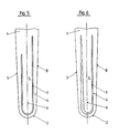
- Fig. 1 zeigt eine Ansicht des distalen Endes einer ersten Ausführungsform des neuen Schaftes;
- Fig. 2 und 3 sind Schnitte II-II bzw. III-III von Fig. 1;
- Fig. 4 bis 6 geben in gleicher Darstellung wie Fig. 1 weitere Ausführungsbeispiele der Erfindung wieder.
- Der allseitig vom distalen Ende 2 her sich konisch erweiternde Schaft 1, von dem nur der distale Bereich dargestellt ist, ist mit einem zwischen 0,5 und 1 mm breiten Schlitz 3 versehen. Dieser durchsetzt die ganze Schaftdicke in Richtung ventral/ dorsal, wie die Fig. 2 und 3 zeigen. Dadurch entsteht ein am nicht dargestellten Knochen oder Zementbett anliegender Randbereich 4 und ein zungenartiger Kernbereich 5.
- Bei Biegebelastungen auf den nicht dargestellten Gelenkkopf bewegt sich der Kernbereich in den Schlitz 3 sowohl in Richtung lateral/distal - d.h. in der Zeichenebene der Figur horizontal - als auch in Richtung ventral/dorsal - d.h. in der Zeichenebene von Fig.2 und 3 vertikal -. Weiterhin hat der Kern noch die Möglichkeit einer Verdrehung um seine Längsachse 6.
- Die Breite des U-förmigen Schlitzes 3 muss dabei zwei entgegengesetzten Anforderungen erfüllen:
- Zum einen soll der Schlitz so schmal sein, dass in ihm kein Knochengewebe einwächst, was seine Breite auf etwa 1 mm begrenzt; zum anderen soll die Schlitzbreite so gross sein, dass der zungenartige Kern 5 bei den geschilderten Bewegungen den Schlitz nicht vollständig überbrückt und den Rand 4 berührt. Denn durch eine Berührung beider Teile 4 und 5 entsteht unerwünschter Metallabrieb. Die Länge der U-Schenkel des Schlitzes 3 in Richtung der Längsachse 6 sollte mehr als ein Drittel der Verankerungslänge des Schaftes im Knochen betragen, um die gewünschte Elastizität im Schaft zu erreichen.
- Wie die Fig. 1 und 4 bis 6 verdeutlichen, können die Schenkel der U-Form parallel zur lateralen und medialen Aussenseite 7, 8 (Fig. 1) oder parallel zur Längsachse 6 (Fig. 4) verlaufen. Damit werden, wie bereits erwähnt, für den Kern 5 entweder eine über die ganze Schlitzhöhe konstante Steifigkeit oder Elastizität oder eine nach proximal zunehmende Steifigkeit erreicht.
- Unterschiedliche Steifigkeiten des Kerns lateral und medial der Längsachse 6 erhält man mit der Ausführungsform nach Fig. 5, bei der der laterale Schenkel der U-Form kürzer ist als der mediale.
- Bei der Ausführungsform nach Fig. 6 erweitert sich der laterale Schenkel, dessen Breite am proximalen Ende gleich derjenigen des medialen ist, nach distal stetig. Seine Breite kann am distalen Ende bis zu etwa 4 mm betragen. Mit dieser Ausführungsform wird dem Kern 5 nach lateral eine grössere Bewegungsmöglichkeit eingeräumt als nach medial, da die Biegebelastungen nach lateral eine grössere Bewegungsamplitude erzeugen als nach medial. Ein Einwachsen von Knochengewebe in den verbreiterten Schlitz 3 ist nicht zu befürchten, weil die praktisch immer vorhandenen Bewegungen eine Bildung solchen Gewebes verhindern.
- Das geeignetste Material für den neuen Schaft sind die in der Implantat-Technik gebräuchlichen Metalle oder Metall-Legierungen; bevorzugt werden dabei Titan oder eine Titan-Legierung.
- Für die Herstellung des Schlitzes 3 hat sich vor allem das Hochdruck-Flüssigkeits-Strahl-Schneiden bewährt.
Claims (6)
- Femurkopfprothese mit einem sich von distal nach proximal allseitig konisch erweiternden Verankerungsschaft (1), der mindestens einen die ganze Schaftdicke durchsetzenden, im wesentlichen in Längsrichtung verlaufenden schmalen Schlitz (3) aufweist, dadurch gekennzeichnet, dass der Schlitz (3) U-förmig im distalen Bereich des Schaftes (1) angeordnet ist.
- Prothese nach Anspruch 1, dadurch gekennzeichnet, dass sich die in Längsrichtung verlaufenden Schenkel des Schlitzes (3) parallel zur Aussenform (7, 8) des Schaftes (1) erstrecken.
- Prothese nach Anspruch 1, dadurch gekennzeichnet, dass die in Längsrichtung verlaufenden Schenkel des Schlitzes (3) parallel zur Schaftachse (6) verlaufen.
- Prothese nach Anspruch 3, dadurch gekennzeichnet, dass der lateral der Schaftachse (6) verlaufende Schenkel kürzer ist als der mediale Schenkel.
- Prothese nach Anspruch 3 oder 4, dadurch gekennzeichnet, dass der laterale Schenkel breiter ist als der mediale, wobei seine Breite, ausgehend von einer gleichen Breite am proximalen Ende, von proximal nach distal stetig zunimmt.
- Prothese nach Anspruch 1, dadurch gekennzeichnet, dass gemessen in der Richtung der Schaftachse (6) die Länge der Schenkel des Schlitzes (3) grösser als ein Drittel der Verankerungslänge des Schaftes im Knochen ist.
Priority Applications (1)
| Application Number | Priority Date | Filing Date | Title |
|---|---|---|---|
| AT91810155T ATE95408T1 (de) | 1990-04-10 | 1991-03-08 | Femurkopfprothese. |
Applications Claiming Priority (2)
| Application Number | Priority Date | Filing Date | Title |
|---|---|---|---|
| CH1212/90 | 1990-04-10 | ||
| CH121290 | 1990-04-10 |
Publications (2)
| Publication Number | Publication Date |
|---|---|
| EP0452253A1 true EP0452253A1 (de) | 1991-10-16 |
| EP0452253B1 EP0452253B1 (de) | 1993-10-06 |
Family
ID=4205132
Family Applications (1)
| Application Number | Title | Priority Date | Filing Date |
|---|---|---|---|
| EP91810155A Expired - Lifetime EP0452253B1 (de) | 1990-04-10 | 1991-03-08 | Femurkopfprothese |
Country Status (4)
| Country | Link |
|---|---|
| US (1) | US5171323A (de) |
| EP (1) | EP0452253B1 (de) |
| AT (1) | ATE95408T1 (de) |
| DE (1) | DE59100446D1 (de) |
Cited By (2)
| Publication number | Priority date | Publication date | Assignee | Title |
|---|---|---|---|---|
| WO2002085260A1 (en) * | 2001-04-19 | 2002-10-31 | Wright Medical Technology, Inc. | Humeral stem with distal tri-slot |
| DE10322174A1 (de) * | 2003-05-14 | 2005-02-10 | Merete Medical Gmbh | Steckadapter für eine Hüftendoprothese |
Families Citing this family (10)
| Publication number | Priority date | Publication date | Assignee | Title |
|---|---|---|---|---|
| US5776204A (en) * | 1996-05-24 | 1998-07-07 | Howmedica Inc. | Asymmetric hip stem |
| US20020120340A1 (en) | 2001-02-23 | 2002-08-29 | Metzger Robert G. | Knee joint prosthesis |
| US7497874B1 (en) | 2001-02-23 | 2009-03-03 | Biomet Manufacturing Corp. | Knee joint prosthesis |
| US7892290B2 (en) * | 2004-05-28 | 2011-02-22 | Smith & Nephew, Inc. | Fluted sleeve hip prosthesis for modular stem |
| US7575603B2 (en) * | 2004-05-28 | 2009-08-18 | Smith & Nephew, Inc. | Fluted intramedullary stem |
| US8187280B2 (en) | 2007-10-10 | 2012-05-29 | Biomet Manufacturing Corp. | Knee joint prosthesis system and method for implantation |
| US8328873B2 (en) | 2007-01-10 | 2012-12-11 | Biomet Manufacturing Corp. | Knee joint prosthesis system and method for implantation |
| US8562616B2 (en) | 2007-10-10 | 2013-10-22 | Biomet Manufacturing, Llc | Knee joint prosthesis system and method for implantation |
| JP5448842B2 (ja) | 2007-01-10 | 2014-03-19 | バイオメト マニファクチャリング コーポレイション | 膝関節プロテーゼシステムおよび埋込み方法 |
| US8163028B2 (en) | 2007-01-10 | 2012-04-24 | Biomet Manufacturing Corp. | Knee joint prosthesis system and method for implantation |
Citations (5)
| Publication number | Priority date | Publication date | Assignee | Title |
|---|---|---|---|---|
| FR2425237A1 (fr) * | 1978-05-09 | 1979-12-07 | Breard Francis | Prothese de hanche a tige flexible |
| FR2549717A1 (fr) * | 1983-07-29 | 1985-02-01 | Cuilleron J | Tige femorale a contacts flexibles pour prothese de hanche |
| WO1989001321A1 (en) * | 1987-08-15 | 1989-02-23 | Laboratorium Für Experimentelle Chirurgie, Forschu | Dynamic self-locking stem for hip prosthesis |
| EP0354142A1 (de) * | 1988-07-28 | 1990-02-07 | Gérard Bascoulergue | Schaft für eine Totalhüftprothese |
| EP0308297B1 (de) * | 1987-09-08 | 1991-08-14 | Pierre Teinturier | Totale Gelenksprothese, besonders für die Hüfte |
Family Cites Families (2)
| Publication number | Priority date | Publication date | Assignee | Title |
|---|---|---|---|---|
| FR2483218B1 (fr) * | 1980-05-30 | 1986-06-27 | Cuilleron J | Tige femorale pour prothese de hanche |
| FR2639822B1 (fr) * | 1988-12-07 | 1997-04-04 | Implants Instr Ch Fab | Anneau visse dans les cotyles osseux |
-
1991
- 1991-03-08 AT AT91810155T patent/ATE95408T1/de not_active IP Right Cessation
- 1991-03-08 EP EP91810155A patent/EP0452253B1/de not_active Expired - Lifetime
- 1991-03-08 DE DE91810155T patent/DE59100446D1/de not_active Expired - Fee Related
- 1991-03-21 US US07/673,018 patent/US5171323A/en not_active Expired - Fee Related
Patent Citations (5)
| Publication number | Priority date | Publication date | Assignee | Title |
|---|---|---|---|---|
| FR2425237A1 (fr) * | 1978-05-09 | 1979-12-07 | Breard Francis | Prothese de hanche a tige flexible |
| FR2549717A1 (fr) * | 1983-07-29 | 1985-02-01 | Cuilleron J | Tige femorale a contacts flexibles pour prothese de hanche |
| WO1989001321A1 (en) * | 1987-08-15 | 1989-02-23 | Laboratorium Für Experimentelle Chirurgie, Forschu | Dynamic self-locking stem for hip prosthesis |
| EP0308297B1 (de) * | 1987-09-08 | 1991-08-14 | Pierre Teinturier | Totale Gelenksprothese, besonders für die Hüfte |
| EP0354142A1 (de) * | 1988-07-28 | 1990-02-07 | Gérard Bascoulergue | Schaft für eine Totalhüftprothese |
Cited By (3)
| Publication number | Priority date | Publication date | Assignee | Title |
|---|---|---|---|---|
| WO2002085260A1 (en) * | 2001-04-19 | 2002-10-31 | Wright Medical Technology, Inc. | Humeral stem with distal tri-slot |
| US6554865B2 (en) | 2001-04-19 | 2003-04-29 | Wright Medical Technology, Inc. | Humeral stem with distal tri-slot |
| DE10322174A1 (de) * | 2003-05-14 | 2005-02-10 | Merete Medical Gmbh | Steckadapter für eine Hüftendoprothese |
Also Published As
| Publication number | Publication date |
|---|---|
| ATE95408T1 (de) | 1993-10-15 |
| US5171323A (en) | 1992-12-15 |
| DE59100446D1 (de) | 1993-11-11 |
| EP0452253B1 (de) | 1993-10-06 |
Similar Documents
| Publication | Publication Date | Title |
|---|---|---|
| DE2440103C3 (de) | Gelenkendoprothese zum Ersetzen von Knochengelenken | |
| EP0135755B1 (de) | Schaft für eine Hüftgelenkprothese | |
| DE2700531C2 (de) | Rahmengerüst für eine Herzklappe | |
| DE69131625T2 (de) | Prothese mit porösen überzug | |
| DE1912630C3 (de) | Hüftgelenk Prothese | |
| DE4041920C2 (de) | Künstliches Kniegelenk | |
| DE69225600T2 (de) | Femurschaftprothese | |
| CH675827A5 (de) | ||
| DE2652824A1 (de) | Gelenkendoprothese fuer ein sprunggelenk | |
| EP0452253B1 (de) | Femurkopfprothese | |
| DE3013155A1 (de) | Tibia-prothese | |
| CH666178A5 (de) | Femurkopfprothese. | |
| EP0131178A2 (de) | Hüftgelenk-Endoprothese mit einem im Oberschenkelknochen zu verankernden Schaft | |
| DE3505997C2 (de) | Hüftgelenkendoprothesen-Oberschenkelteil | |
| DE2908898A1 (de) | Prothesengelenk | |
| DE69514366T2 (de) | Hüftprothese | |
| CH678595A5 (de) | ||
| EP0027160A2 (de) | Hüftgelenkprothese | |
| DE2736443C2 (de) | Penis-Implantat | |
| CH677442A5 (de) | ||
| EP0144588A2 (de) | Hüftgelenkspfanne | |
| EP0112435B1 (de) | Femurkopfprothese | |
| EP0550117B1 (de) | Schaftprothese | |
| DE3819948C2 (de) | ||
| DE8213101U1 (de) | Femorale Komponente einer Hüftgelenkendoprothese |
Legal Events
| Date | Code | Title | Description |
|---|---|---|---|
| PUAI | Public reference made under article 153(3) epc to a published international application that has entered the european phase |
Free format text: ORIGINAL CODE: 0009012 |
|
| AK | Designated contracting states |
Kind code of ref document: A1 Designated state(s): AT CH DE FR GB IT LI |
|
| 17P | Request for examination filed |
Effective date: 19911029 |
|
| 17Q | First examination report despatched |
Effective date: 19930315 |
|
| GRAA | (expected) grant |
Free format text: ORIGINAL CODE: 0009210 |
|
| AK | Designated contracting states |
Kind code of ref document: B1 Designated state(s): AT CH DE FR GB IT LI |
|
| ITF | It: translation for a ep patent filed | ||
| REF | Corresponds to: |
Ref document number: 95408 Country of ref document: AT Date of ref document: 19931015 Kind code of ref document: T |
|
| RAP2 | Party data changed (patent owner data changed or rights of a patent transferred) |
Owner name: SULZER MEDIZINALTECHNIK AG |
|
| REF | Corresponds to: |
Ref document number: 59100446 Country of ref document: DE Date of ref document: 19931111 |
|
| GBT | Gb: translation of ep patent filed (gb section 77(6)(a)/1977) |
Effective date: 19931019 |
|
| ET | Fr: translation filed | ||
| PLBE | No opposition filed within time limit |
Free format text: ORIGINAL CODE: 0009261 |
|
| 26N | No opposition filed | ||
| REG | Reference to a national code |
Ref country code: GB Ref legal event code: IF02 |
|
| PGFP | Annual fee paid to national office [announced via postgrant information from national office to epo] |
Ref country code: GB Payment date: 20020222 Year of fee payment: 12 |
|
| PGFP | Annual fee paid to national office [announced via postgrant information from national office to epo] |
Ref country code: CH Payment date: 20020225 Year of fee payment: 12 |
|
| PGFP | Annual fee paid to national office [announced via postgrant information from national office to epo] |
Ref country code: AT Payment date: 20020307 Year of fee payment: 12 |
|
| PGFP | Annual fee paid to national office [announced via postgrant information from national office to epo] |
Ref country code: DE Payment date: 20020309 Year of fee payment: 12 |
|
| PGFP | Annual fee paid to national office [announced via postgrant information from national office to epo] |
Ref country code: FR Payment date: 20020315 Year of fee payment: 12 |
|
| PG25 | Lapsed in a contracting state [announced via postgrant information from national office to epo] |
Ref country code: GB Free format text: LAPSE BECAUSE OF NON-PAYMENT OF DUE FEES Effective date: 20030308 Ref country code: AT Free format text: LAPSE BECAUSE OF NON-PAYMENT OF DUE FEES Effective date: 20030308 |
|
| PG25 | Lapsed in a contracting state [announced via postgrant information from national office to epo] |
Ref country code: LI Free format text: LAPSE BECAUSE OF NON-PAYMENT OF DUE FEES Effective date: 20030331 Ref country code: CH Free format text: LAPSE BECAUSE OF NON-PAYMENT OF DUE FEES Effective date: 20030331 |
|
| PG25 | Lapsed in a contracting state [announced via postgrant information from national office to epo] |
Ref country code: DE Free format text: LAPSE BECAUSE OF NON-PAYMENT OF DUE FEES Effective date: 20031001 |
|
| GBPC | Gb: european patent ceased through non-payment of renewal fee |
Effective date: 20030308 |
|
| REG | Reference to a national code |
Ref country code: CH Ref legal event code: PL |
|
| PG25 | Lapsed in a contracting state [announced via postgrant information from national office to epo] |
Ref country code: FR Free format text: LAPSE BECAUSE OF NON-PAYMENT OF DUE FEES Effective date: 20031127 |
|
| REG | Reference to a national code |
Ref country code: FR Ref legal event code: ST |
|
| PG25 | Lapsed in a contracting state [announced via postgrant information from national office to epo] |
Ref country code: IT Free format text: LAPSE BECAUSE OF NON-PAYMENT OF DUE FEES;WARNING: LAPSES OF ITALIAN PATENTS WITH EFFECTIVE DATE BEFORE 2007 MAY HAVE OCCURRED AT ANY TIME BEFORE 2007. THE CORRECT EFFECTIVE DATE MAY BE DIFFERENT FROM THE ONE RECORDED. Effective date: 20050308 |