EP0452326B1 - Schlitzlüfter - Google Patents
Schlitzlüfter Download PDFInfo
- Publication number
- EP0452326B1 EP0452326B1 EP89909599A EP89909599A EP0452326B1 EP 0452326 B1 EP0452326 B1 EP 0452326B1 EP 89909599 A EP89909599 A EP 89909599A EP 89909599 A EP89909599 A EP 89909599A EP 0452326 B1 EP0452326 B1 EP 0452326B1
- Authority
- EP
- European Patent Office
- Prior art keywords
- slot
- facing strip
- backing member
- ventilator
- link
- Prior art date
- Legal status (The legal status is an assumption and is not a legal conclusion. Google has not performed a legal analysis and makes no representation as to the accuracy of the status listed.)
- Expired - Lifetime
Links
Images

Classifications
-
- F—MECHANICAL ENGINEERING; LIGHTING; HEATING; WEAPONS; BLASTING
- F24—HEATING; RANGES; VENTILATING
- F24F—AIR-CONDITIONING; AIR-HUMIDIFICATION; VENTILATION; USE OF AIR CURRENTS FOR SCREENING
- F24F13/00—Details common to, or for air-conditioning, air-humidification, ventilation or use of air currents for screening
- F24F13/08—Air-flow control members, e.g. louvres, grilles, flaps or guide plates
- F24F13/10—Air-flow control members, e.g. louvres, grilles, flaps or guide plates movable, e.g. dampers
- F24F13/16—Air-flow control members, e.g. louvres, grilles, flaps or guide plates movable, e.g. dampers built up of parallelly-movable plates
-
- F—MECHANICAL ENGINEERING; LIGHTING; HEATING; WEAPONS; BLASTING
- F24—HEATING; RANGES; VENTILATING
- F24F—AIR-CONDITIONING; AIR-HUMIDIFICATION; VENTILATION; USE OF AIR CURRENTS FOR SCREENING
- F24F13/00—Details common to, or for air-conditioning, air-humidification, ventilation or use of air currents for screening
- F24F13/08—Air-flow control members, e.g. louvres, grilles, flaps or guide plates
- F24F13/18—Air-flow control members, e.g. louvres, grilles, flaps or guide plates specially adapted for insertion in flat panels, e.g. in door or window-pane
Definitions
- This invention relates to a slot ventilator, for example for use in a room with a sealed window or double glazing wherein it is desirable to provide ventilation without having to open the window.
- Slot ventilators are known but they have always required a substantial dimension perpendicular to the face containing the slot in order to achieve effective opening of the slot by moving a facing strip for closing the slot by movement essentially parallel with the face containing the slot.
- a slot ventilator comprises an elongate slotted backing member and an elongate facing strip mounted by a spaced parallel motion link to the backing member such that longitudinal movement of the facing strip also produces movement thereof towards or away from the backing member between a closed position obstructing a slot in the backing member and a forward open position.
- the link is pivoted at one end to a small projection extending from the facing strip into the slot.
- the link is dog-leg shaped and is pivotally connected, at the angle in the dog-leg, to the backing member. The other end of the link is connected to a rod for operating the ventilator between its closed and open positions.
- GB-A-1417751 discloses a slot ventilator comprising an elongate slotted backing member having two side walls defining a slot therebetween, and an elongate facing strip mounted by a spaced parallel-motion link to the backing member such that longitudinal movement of the facing strip also produces movement thereof towards or away from the backing member between a closed position obstructing the slot, and a forward open position, the link being pivoted at one end to a rib extending from the facing strip into the slot and at the other end to the side walls, the rib comprising a generally flat plate having a longitudinal rear edge which is spaced from the facing strip, the pivotal connection between the link and the side walls extending between the side walls.
- the cutaway enables the pivotal connections respectively to the rib and the backing member to be separated by only a short distance in a direction perpendicular to the plane of the slot while the, or each, link need only be a little longer than the desired amount of opening movement of the facing strip away from the backing member.
- Each link is conveniently of "U” cross-section being pivoted to the backing member,at the bottom of the “U” and pivoted to the rib at the top of the "U” where the two arms are on either side of the rib.
- the two arms of the "U” may be closely spaced on either side of the rib to provide an adequate support when the facing strip is in the open position. Inspite of the cutaway to accommodate the pivot to the backing member, the rib can be of sufficient extent into the slot to provide adequate engagement, surfaces for the arms of the "U” of the, or each, link.
- both the backing member and the facing strip are formed from extruded sections of uniform cross-section, possibly from aluminium or an aluminium alloy or of a suitable plastics material.
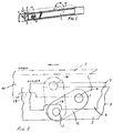
- Figure 1 is a perspective view of a slot ventilator.
- Figure 2 is a diagrammatic plan view to an increased scale showing the relationship between the backing member and the facing strip and a link in each of the closed and the open positions, and
- Figure 3 is a sectional end view of Figure 2 with the facing strip in the open position to the left of the centre line and in the closed position to the right of the centre line.
- the slot ventilator shown generally at 1 comprises a backing member 3, a facing strip 7 and a parallel motion linkage supporting the facing strip on the backing member.
- the backing member 3 comprises an elongate strip with a slot 4 extending lengthwise along it, and two parallel flanges 5 extending rearwardly from the slotted strip.
- the flanges 5 are disposed close to the longitudinal edges of the slotted strip, on either side of the slot 4.
- the facing strip 7 has a rearwardly extending longitudinal rib 8 which at all times projects into the slot.
- the parallel motion linkage comprises two parallel links 12 made of a tough, resilient plastics material such as that sold under the trade mark "Delrin".
- Each link 12 is “U” shaped, the gap between the arms of the “U” accommodating the rib 8, and the outer faces of these arms lying between and adjacent to or in contact with the flanges 5 of the backing member 3.
- Pivot pins 13 are provided to connect the ends of the links 12 to the flanges 5, and further pins 14 to connect the free ends of the arms of the links 12 to the rib 8, to allow movement of the facing strip 7 parallel to the backing member 3.
- a handle 9 is provided protruding from the facing strip 7 in order to provide more manual purchase.
- the links 12 are disposed so as to lie obliquely to the plane containing the axes of the pivot pins 13 when the facing strip 7 lies against the slotted strip portion of the backing member 3, closing the slot in the latter.
- the obliquity of the links 12 causes the facing strip 7 to move outwardly as well as longitudinally relative to the backing member 3 while remaining parallel to the latter, to an open position as shown in chain lines in Figure 2 and to the left of Figure 3.
- the rib 8 serves also as a stop. Its edge 10 is positioned so that it butts against one end of the slot 4 at the fully open setting.
- the length of the rib 8 is such that the ventilator can thus be opened to the point where the links 12 have just passed through the position in which they are disposed in the dead-centre position, in order that deliberate longitudinal movement of the facing strip 7 in the reverse direction is required to close the ventilator, and the facing strip 7 cannot normally be slammed shut by a gust of air.
- Both the facing strip and the backing member may be made from extrusions of uniform cross-section, e g of aluminium, and machined as necessary.
- the rear edge of the rib 8 Adjacent the pivot pins 13, the rear edge of the rib 8 is cut away at 18 so that in the closed position, shown in solid lines in Figure 2, the pivot pins do not interfere with the rear edge of the rib and that means that the pivot pins 13 can be mounted close to the outer face of the backing member, which both reduces the dimension of the ventilator in the vertical direction in Figures 2 and 3 and incidentally reduces the amount of material necessary in both the backing member and the facing strip.
- Figure 2 also shows how in the closed position in solid lines the links 12 are only a little oblique to the face of the backing member containing the slot. In fact in the example shown in Figure 2 the angle is about 30 degrees.
- the present embodiment provides a ventilator having an opening movement of about 40% of the overall ventilator depth.
- Other embodiments could have corresponding values of for example 30% or 50%.
- the cutaway portion 18 could be semi-circular rather than rectangular.
- the slot ventilator is conveniently installed in a passage in a window frame or sash.
Landscapes
- Engineering & Computer Science (AREA)
- Chemical & Material Sciences (AREA)
- Combustion & Propulsion (AREA)
- Mechanical Engineering (AREA)
- General Engineering & Computer Science (AREA)
- Specific Sealing Or Ventilating Devices For Doors And Windows (AREA)
- Structures Of Non-Positive Displacement Pumps (AREA)
- Air-Flow Control Members (AREA)
- Non-Reversible Transmitting Devices (AREA)
- Separation Using Semi-Permeable Membranes (AREA)
- Motor Or Generator Cooling System (AREA)
- Treating Waste Gases (AREA)
- Diaphragms For Electromechanical Transducers (AREA)
- Duct Arrangements (AREA)
- Fittings On The Vehicle Exterior For Carrying Loads, And Devices For Holding Or Mounting Articles (AREA)
- Gas Separation By Absorption (AREA)
- Turbine Rotor Nozzle Sealing (AREA)
- Percussion Or Vibration Massage (AREA)
Claims (7)
- Schlitzlüfter (1), welcher ein längliches geschlitztes Trägerelement (3) mit zwei Seitenwänden (5), welche zwischen ihnen einen Schlitz (4) definieren, und einen länglichen Verblendstreifen (7) aufweist, der durch ein beabstandetes Parallelführungsverbindungsstück (12) an dem Trägerelement befestigt ist, so daß eine längsgerichtete Bewegung des Verblendstreifens auch dessen Bewegung zu dem Trägerelement hin oder von diesem weg zwischen einer Schließstellung, in welcher der Schlitz abgeschlossen ist, und einer vorderen Offenstellung bewirkt, wobei das Verbindungsstück an einem Ende an eine Rippe (8) angelenkt ist, die sich von dem Verblendstreifen in den Schlitz erstreckt, und am anderen Ende an den Seitenwänden, wobei die Rippe (8) eine im allgemeinen flache Platte mit einer länglichen hinteren Kante umfaßt, die von dem Verblendstreifen beabstandet ist, und sich die Schwenkverbindung (13) zwischen dem Verbindungsstück und den Seitenwänden zwischen den Seitenwänden erstreckt, dadurch gekennzeichnet, daß die hintere Kante der Rippe (8) einen weggeschnittenen Teil (18) aufweist, der zur Aufnahme der Schwenkverbindung (13) angeordnet ist, die sich zwischen den Seitenwänden erstreckt, wenn sich der Verblendstreifen in der Schließstellung befindet.
- Schlitzlüfter nach Anspruch 1, der zwei Parallelführungsverbindungsstücke (12) und zwei entsprechende weggeschnittene Teile (18) aufweist.
- Schlitzlüfter nach Anspruch 1 oder Anspruch 2, wobei das oder jedes Verbindungsstück (12) einen U-förmigen Querschnitt aufweist, die Rippe (8) zwischen den Armen des U aufgenommen und an deren oberen Enden schwenkbar ist; das oder jedes Verbindungsstück an der Basis des U zwischen den Seitenwänden (5) schwenkbar ist, welche erste und zweite parallele, sich nach hinten erstreckende Flansche des Trägerelements (3) aufweisen.
- Schlitzlüfter nach einem der vorangehenden Ansprüche, wobei, wenn sich der Verblendstreifen (7) in der Schließstellung befindet, die Ebene oder Ebenen, welche die Schwenkverbindungen zwischen dem oder jedem Verbindungsstück (12) und dem Trägerelement und dem oder jedem Verbindungsstück und der Rippe (8) enthalten, einen flachen schiefen Winkel mit der allgemeinen Ebene des Verblendstreifens bilden.
- Schlitzlüfter nach Anspruch 4, wobei der flache schiefe Winkel im wesentlichen nicht größer als 30° ist.
- Schlitzlüfter nach einem der vorangehenden Ansprüche, wobei die Strecke, die sich der Verblendstreifen (7) nach vorne aus der Schließstellung in die Offenstellung bewegt, mindestens 30% der gesamten Tiefe des Lüfters beträgt, u.zw. gemessen von der vorderen Oberfläche des Verblendstreifens in dessen Schließstellung bis zur Rückseite des Trägerelements.
- Schlitzlüfter nach Anspruch 6, wobei die Strecke im wesentlichen 40% der gesamten Lüftertiefe beträgt.
Applications Claiming Priority (3)
| Application Number | Priority Date | Filing Date | Title |
|---|---|---|---|
| GB8820336 | 1988-08-26 | ||
| GB888820336A GB8820336D0 (en) | 1988-08-26 | 1988-08-26 | Slot ventilators |
| PCT/GB1989/000917 WO1990002298A1 (en) | 1988-08-26 | 1989-08-10 | Slot ventilators |
Publications (2)
| Publication Number | Publication Date |
|---|---|
| EP0452326A1 EP0452326A1 (de) | 1991-10-23 |
| EP0452326B1 true EP0452326B1 (de) | 1994-11-09 |
Family
ID=10642792
Family Applications (1)
| Application Number | Title | Priority Date | Filing Date |
|---|---|---|---|
| EP89909599A Expired - Lifetime EP0452326B1 (de) | 1988-08-26 | 1989-08-10 | Schlitzlüfter |
Country Status (9)
| Country | Link |
|---|---|
| US (1) | US5194040A (de) |
| EP (1) | EP0452326B1 (de) |
| AT (1) | ATE114040T1 (de) |
| AU (1) | AU4077889A (de) |
| DE (1) | DE68919371T2 (de) |
| DK (1) | DK172302B1 (de) |
| GB (1) | GB8820336D0 (de) |
| HU (1) | HU209202B (de) |
| WO (1) | WO1990002298A1 (de) |
Families Citing this family (5)
| Publication number | Priority date | Publication date | Assignee | Title |
|---|---|---|---|---|
| GB2275104B (en) * | 1993-02-10 | 1997-01-08 | Titon Hardware | Ventilator |
| AU658785B1 (en) * | 1994-03-30 | 1995-04-27 | J. Kral | Venturi window |
| US6299527B1 (en) * | 2000-03-31 | 2001-10-09 | Val Products, Inc. | Ventilation control system for a building |
| US7393271B2 (en) * | 2005-07-18 | 2008-07-01 | Enclos Corporation | Ventilator |
| US20130133243A1 (en) | 2011-06-28 | 2013-05-30 | Basf Se | Quaternized nitrogen compounds and use thereof as additives in fuels and lubricants |
Family Cites Families (9)
| Publication number | Priority date | Publication date | Assignee | Title |
|---|---|---|---|---|
| GB190515832A (en) * | 1905-08-02 | 1906-03-08 | Robert Vaughan Humphreys | An Improved Device for Ventilating Greenhouses, Conservatories, Sheds, Outhouses and the like. |
| US2207671A (en) * | 1937-07-30 | 1940-07-09 | King Douglas Hobbis | Ventilating apparatus |
| US3392658A (en) * | 1967-02-23 | 1968-07-16 | Western Eng & Mfg Co | Damper operating means |
| NO119045B (de) * | 1968-12-09 | 1970-03-16 | O Berg | |
| GB1417751A (en) * | 1973-01-09 | 1975-12-17 | Titon Hardware | Slot ventilators |
| GB1582946A (en) * | 1977-07-06 | 1981-01-21 | Norcros Investments Ltd | Ventilators |
| NO141351C (no) * | 1978-03-21 | 1980-02-20 | Titon Hardware | Spalteventil. |
| US4727797A (en) * | 1986-07-03 | 1988-03-01 | Titon Hardware Limited | Secondary window ventilators |
| US4736677A (en) * | 1986-11-04 | 1988-04-12 | Titon Hardware Limited | Ventilator assemblies |
-
1988
- 1988-08-26 GB GB888820336A patent/GB8820336D0/en active Pending
-
1989
- 1989-08-10 DE DE68919371T patent/DE68919371T2/de not_active Expired - Fee Related
- 1989-08-10 HU HU895182A patent/HU209202B/hu not_active IP Right Cessation
- 1989-08-10 EP EP89909599A patent/EP0452326B1/de not_active Expired - Lifetime
- 1989-08-10 WO PCT/GB1989/000917 patent/WO1990002298A1/en not_active Ceased
- 1989-08-10 US US07/678,946 patent/US5194040A/en not_active Expired - Lifetime
- 1989-08-10 AT AT89909599T patent/ATE114040T1/de not_active IP Right Cessation
- 1989-08-10 AU AU40778/89A patent/AU4077889A/en not_active Abandoned
-
1991
- 1991-02-26 DK DK032991A patent/DK172302B1/da not_active IP Right Cessation
Also Published As
| Publication number | Publication date |
|---|---|
| HU895182D0 (en) | 1991-08-28 |
| HU209202B (en) | 1994-03-28 |
| DE68919371D1 (de) | 1994-12-15 |
| DK32991D0 (da) | 1991-02-26 |
| DE68919371T2 (de) | 1995-03-16 |
| GB8820336D0 (en) | 1988-09-28 |
| EP0452326A1 (de) | 1991-10-23 |
| HUT56617A (en) | 1991-09-30 |
| AU4077889A (en) | 1990-03-23 |
| WO1990002298A1 (en) | 1990-03-08 |
| ATE114040T1 (de) | 1994-11-15 |
| DK172302B1 (da) | 1998-03-02 |
| DK32991A (da) | 1991-02-26 |
| US5194040A (en) | 1993-03-16 |
Similar Documents
| Publication | Publication Date | Title |
|---|---|---|
| US4555829A (en) | Supporting stays for swingable windows having friction and sliding pivots | |
| EP0508698A3 (de) | Industrietor mit freigebbarem Holm | |
| GB2038407A (en) | Tape drive window regulator mechanism | |
| US4571776A (en) | Releasable window hinge | |
| EP0452326B1 (de) | Schlitzlüfter | |
| CA2161041A1 (en) | Pocket Door Latch | |
| ES2076797T3 (es) | Bisagra para muebles. | |
| US4736677A (en) | Ventilator assemblies | |
| CA2202047A1 (en) | Method and apparatus for securing a sash within a frame | |
| EP0455684B1 (de) | Lüfter | |
| US4518012A (en) | Air damper assembly with movable blades | |
| CA2168857A1 (en) | Slot ventilator | |
| AU3960199A (en) | Assembly comprising a casing and a sliding panel | |
| WO1999061742A8 (en) | Slatted door | |
| KR100484089B1 (ko) | 루버시스템 작동 장치 | |
| GB2239309A (en) | Window/door ventilators of modular construction | |
| US4991459A (en) | Linear motion control arrangement | |
| GB2311848A (en) | Slot ventilator | |
| EP0060112B1 (de) | Eine Drosseleinrichtung für Lüftungsanlagen mit einer Anzahl von parallelen und drehbaren rechteckigen Klappen | |
| USRE23182E (en) | Adjustable louver shutter or blind | |
| GB2251934A (en) | A ventilator of flexible material distorts to open or close | |
| GB2258268A (en) | Friction stays. | |
| NO172512B (no) | Slisseventilator | |
| EP1632628A2 (de) | Scharnier und Tür oder seitlich angehängtes Fenster mit einem solchen Scharnier | |
| ES272984U (es) | Dispositivo de articulacion perfeccionado para puertas y similares |
Legal Events
| Date | Code | Title | Description |
|---|---|---|---|
| PUAI | Public reference made under article 153(3) epc to a published international application that has entered the european phase |
Free format text: ORIGINAL CODE: 0009012 |
|
| 17P | Request for examination filed |
Effective date: 19910215 |
|
| AK | Designated contracting states |
Kind code of ref document: A1 Designated state(s): AT BE CH DE FR GB IT LI LU NL SE |
|
| 17Q | First examination report despatched |
Effective date: 19930707 |
|
| GRAA | (expected) grant |
Free format text: ORIGINAL CODE: 0009210 |
|
| ITF | It: translation for a ep patent filed | ||
| AK | Designated contracting states |
Kind code of ref document: B1 Designated state(s): AT BE CH DE FR GB IT LI LU NL SE |
|
| PG25 | Lapsed in a contracting state [announced via postgrant information from national office to epo] |
Ref country code: LI Effective date: 19941109 Ref country code: CH Effective date: 19941109 |
|
| REF | Corresponds to: |
Ref document number: 114040 Country of ref document: AT Date of ref document: 19941115 Kind code of ref document: T |
|
| REF | Corresponds to: |
Ref document number: 68919371 Country of ref document: DE Date of ref document: 19941215 |
|
| ET | Fr: translation filed | ||
| REG | Reference to a national code |
Ref country code: CH Ref legal event code: PL |
|
| PG25 | Lapsed in a contracting state [announced via postgrant information from national office to epo] |
Ref country code: LU Free format text: LAPSE BECAUSE OF NON-PAYMENT OF DUE FEES Effective date: 19950831 |
|
| PLBE | No opposition filed within time limit |
Free format text: ORIGINAL CODE: 0009261 |
|
| STAA | Information on the status of an ep patent application or granted ep patent |
Free format text: STATUS: NO OPPOSITION FILED WITHIN TIME LIMIT |
|
| 26N | No opposition filed | ||
| REG | Reference to a national code |
Ref country code: GB Ref legal event code: IF02 |
|
| PGFP | Annual fee paid to national office [announced via postgrant information from national office to epo] |
Ref country code: FR Payment date: 20030808 Year of fee payment: 15 |
|
| PGFP | Annual fee paid to national office [announced via postgrant information from national office to epo] |
Ref country code: AT Payment date: 20030813 Year of fee payment: 15 |
|
| PGFP | Annual fee paid to national office [announced via postgrant information from national office to epo] |
Ref country code: DE Payment date: 20030822 Year of fee payment: 15 |
|
| PGFP | Annual fee paid to national office [announced via postgrant information from national office to epo] |
Ref country code: NL Payment date: 20030831 Year of fee payment: 15 |
|
| PGFP | Annual fee paid to national office [announced via postgrant information from national office to epo] |
Ref country code: BE Payment date: 20031009 Year of fee payment: 15 |
|
| PGFP | Annual fee paid to national office [announced via postgrant information from national office to epo] |
Ref country code: SE Payment date: 20040806 Year of fee payment: 16 |
|
| PG25 | Lapsed in a contracting state [announced via postgrant information from national office to epo] |
Ref country code: AT Free format text: LAPSE BECAUSE OF NON-PAYMENT OF DUE FEES Effective date: 20040810 |
|
| PG25 | Lapsed in a contracting state [announced via postgrant information from national office to epo] |
Ref country code: BE Free format text: LAPSE BECAUSE OF NON-PAYMENT OF DUE FEES Effective date: 20040831 |
|
| BERE | Be: lapsed |
Owner name: *TITON HARDWARE LTD Effective date: 20040831 |
|
| PG25 | Lapsed in a contracting state [announced via postgrant information from national office to epo] |
Ref country code: DE Free format text: LAPSE BECAUSE OF NON-PAYMENT OF DUE FEES Effective date: 20050301 Ref country code: NL Free format text: LAPSE BECAUSE OF NON-PAYMENT OF DUE FEES Effective date: 20050301 |
|
| PG25 | Lapsed in a contracting state [announced via postgrant information from national office to epo] |
Ref country code: FR Free format text: LAPSE BECAUSE OF NON-PAYMENT OF DUE FEES Effective date: 20050429 |
|
| NLV4 | Nl: lapsed or anulled due to non-payment of the annual fee |
Effective date: 20050301 |
|
| REG | Reference to a national code |
Ref country code: FR Ref legal event code: ST |
|
| PG25 | Lapsed in a contracting state [announced via postgrant information from national office to epo] |
Ref country code: IT Free format text: LAPSE BECAUSE OF NON-PAYMENT OF DUE FEES Effective date: 20050810 |
|
| PG25 | Lapsed in a contracting state [announced via postgrant information from national office to epo] |
Ref country code: SE Free format text: LAPSE BECAUSE OF NON-PAYMENT OF DUE FEES Effective date: 20050811 |
|
| EUG | Se: european patent has lapsed | ||
| BERE | Be: lapsed |
Owner name: *TITON HARDWARE LTD Effective date: 20040831 |
|
| PGFP | Annual fee paid to national office [announced via postgrant information from national office to epo] |
Ref country code: GB Payment date: 20070809 Year of fee payment: 19 |
|
| GBPC | Gb: european patent ceased through non-payment of renewal fee |
Effective date: 20080810 |
|
| PG25 | Lapsed in a contracting state [announced via postgrant information from national office to epo] |
Ref country code: GB Free format text: LAPSE BECAUSE OF NON-PAYMENT OF DUE FEES Effective date: 20080810 |