EP0452343B1 - Bielle motrice - Google Patents
Bielle motrice Download PDFInfo
- Publication number
- EP0452343B1 EP0452343B1 EP90900158A EP90900158A EP0452343B1 EP 0452343 B1 EP0452343 B1 EP 0452343B1 EP 90900158 A EP90900158 A EP 90900158A EP 90900158 A EP90900158 A EP 90900158A EP 0452343 B1 EP0452343 B1 EP 0452343B1
- Authority
- EP
- European Patent Office
- Prior art keywords
- connecting rod
- casting
- core
- cast
- casting material
- Prior art date
- Legal status (The legal status is an assumption and is not a legal conclusion. Google has not performed a legal analysis and makes no representation as to the accuracy of the status listed.)
- Expired - Lifetime
Links
Images
Classifications
-
- F—MECHANICAL ENGINEERING; LIGHTING; HEATING; WEAPONS; BLASTING
- F16—ENGINEERING ELEMENTS AND UNITS; GENERAL MEASURES FOR PRODUCING AND MAINTAINING EFFECTIVE FUNCTIONING OF MACHINES OR INSTALLATIONS; THERMAL INSULATION IN GENERAL
- F16C—SHAFTS; FLEXIBLE SHAFTS; ELEMENTS OR CRANKSHAFT MECHANISMS; ROTARY BODIES OTHER THAN GEARING ELEMENTS; BEARINGS
- F16C7/00—Connecting-rods or like links pivoted at both ends; Construction of connecting-rod heads
- F16C7/02—Constructions of connecting-rods with constant length
- F16C7/023—Constructions of connecting-rods with constant length for piston engines, pumps or the like
-
- F—MECHANICAL ENGINEERING; LIGHTING; HEATING; WEAPONS; BLASTING
- F02—COMBUSTION ENGINES; HOT-GAS OR COMBUSTION-PRODUCT ENGINE PLANTS
- F02F—CYLINDERS, PISTONS OR CASINGS, FOR COMBUSTION ENGINES; ARRANGEMENTS OF SEALINGS IN COMBUSTION ENGINES
- F02F7/00—Casings, e.g. crankcases
- F02F7/0085—Materials for constructing engines or their parts
-
- F—MECHANICAL ENGINEERING; LIGHTING; HEATING; WEAPONS; BLASTING
- F05—INDEXING SCHEMES RELATING TO ENGINES OR PUMPS IN VARIOUS SUBCLASSES OF CLASSES F01-F04
- F05C—INDEXING SCHEME RELATING TO MATERIALS, MATERIAL PROPERTIES OR MATERIAL CHARACTERISTICS FOR MACHINES, ENGINES OR PUMPS OTHER THAN NON-POSITIVE-DISPLACEMENT MACHINES OR ENGINES
- F05C2253/00—Other material characteristics; Treatment of material
- F05C2253/16—Fibres
Definitions
- the connecting rod of an internal combustion engine is exposed to a high pressure load generated by the ignition pressure during operation.
- the connecting rod shaft is usually designed with an I-shaped cross section.
- Such a connecting rod can be produced by forging or casting with relatively little effort.
- connecting rods with a connecting rod shaft with an H-shaped cross section are used, which have a significantly greater resistance to buckling, but are very expensive to manufacture.
- fiber-reinforced connecting rods increased strength is generally achieved, but also at the expense of significantly higher manufacturing costs.
- the tensile strength is increased substantially to the same extent, although the tensile load in a naturally aspirated engine is only about 1/8 and in a turbo engine only about 1/14 of the maximum pressure load.
- the known connecting rods are therefore extremely oversized in terms of the tensile load.
- the invention relates to a connecting rod for an internal combustion engine with a casting, which has a piston pin eye, half a crankshaft bearing eye and a connecting rod shaft connecting them, into which an elongated, the core, which extends essentially over the entire length of the connecting rod shaft, is cast in from a material which has a smaller coefficient of linear expansion, a lower specific weight and a higher melting point than the casting material.
- the core consists of inorganic fibers, for example stainless steel fibers or carbon fibers, which are connected to one another by a copper solder before being cast with the casting material, in order to increase the packing density to increase the To achieve the strength of the connecting rod.
- inorganic fibers for example stainless steel fibers or carbon fibers
- a copper solder before being cast with the casting material
- This requires an intimate metallogical connection of the carbon fibers to the casting material, which is improved by the copper solder and by the fact that the casting material penetrates into the spaces between the carbon fibers.
- FR-A-2502036 it is also known to produce the casting from a light metal alloy (e.g. aluminum) and the component from graphite fibers connected with copper.
- the invention has for its object to provide a connecting rod of the generic type, which is characterized by a low weight and high resistance to kinking and can be manufactured inexpensively compared to fiber-reinforced connecting rods.
- a tensile stress is generated by the core in the cast material in the manufacture of the connecting rod, by which the compressive stress occurring during operation is reduced.
- the connecting rod can thus be designed for a lower maximum compressive stress and can therefore be made lighter.
- the connecting rod according to the invention is produced in a conventional manner by inserting the core into the mold and then casting the casting material around it.
- the core When using steel as the casting material, the core is heated to approximately 500-700 ° and expands accordingly.
- the liquid casting material cools down and after the solidification temperature has been reached, the contraction of the solidifying casting material begins to pressurize the core. Since the coefficient of expansion of the core is smaller than that of the casting material, the casting material cannot contract freely and tensile stresses build up in it. When the ignition forces are subjected to pressure during operation, these tensile stresses are reduced before the connecting rod is subjected to pressure. This allows the connecting rod to be designed according to the resulting compressive forces, which are smaller than with the conventional design.
- tensile stresses can be generated in the casting material in the production of the connecting rod according to the invention, which can amount to up to 60% of the maximum compressive stresses occurring during operation.
- the connecting rod shaft then only needs to be designed for around 40% of the maximum compressive stress occurring during operation, which can lead to a weight saving of up to 60% for the connecting rod shaft with a connecting rod with the same kink resistance.
- For steel as a casting material and graphite for the The core can achieve a weight reduction of at least 20-30% for the connecting rod.
- Preferred materials for the core are graphite and ceramic materials, in particular sintered bodies made of boron nitride, silicon nitride, silicon carbide and aluminum titanate (Al2TiO5) and, if steel is used as the casting material, also titanium.
- the table below shows the characteristic values of these materials relevant to the invention. ⁇ ( ⁇ m / m ° K) ⁇ (g / cm3) T s
- graphite is a preferred material for the core due to its small coefficient of linear expansion and its low weight, since on the one hand it can generate a high tensile stress in the casting material and on the other hand only slightly increases the weight of the casting.
- the specified ceramic materials are equally suitable for the specified casting materials. With steel as the casting material, titanium is also possible for the core, the coefficient of expansion and weight of which are considerably lower than those of steel.
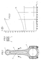
- the connecting rod for an internal combustion engine shown in FIG. 1 consists of a cast part which has a piston pin eye 1, a half crankshaft bearing eye 2 and a connecting rod shaft 3 which connects parts 1 and 2.
- a core 4 is cast, which consists of a material that has a lower specific weight, a smaller linear expansion coefficient and a higher melting point than the casting material.
- the diagram in FIG. 3 shows the change in the linear coefficient of thermal expansion of graphite (C), titanium (Ti), steel (Fe) and a light metal alloy (Al) as a function of the temperature (T). While the thermal expansion of graphite in the area of interest here remains essentially the same up to the solidification temperature of the casting material, which also applies approximately to the ceramic materials specified for the core, increases the coefficient of thermal expansion for the cast material increases to a greater or lesser extent. When the casting material cools below the solidification temperature, which is about 800 ° - 1000 ° C for steel and titanium and about 500 ° C for the light alloy, there is a strong contraction of the casting material, while the coefficient of expansion of the material of the core 4 im remains essentially constant. Since the casting material is prevented from contracting freely by the core 4, a high tensile stress is built up in the casting material, which, as previously described, considerably reduces the maximum pressure load on the connecting rod during operation.
- the casting process should be carried out under at least partial vacuum in order to avoid decomposition of the graphite and, if steel is used as the casting material, to prevent it from carburizing.
Landscapes
- Engineering & Computer Science (AREA)
- General Engineering & Computer Science (AREA)
- Mechanical Engineering (AREA)
- Chemical & Material Sciences (AREA)
- Combustion & Propulsion (AREA)
- Shafts, Cranks, Connecting Bars, And Related Bearings (AREA)
Abstract
Claims (3)
- Bielle pour un moteur à combustion interne, comprenant une pièce moulée en fonte avec un bossage du palier d'axe de piston (1), un demi-coussinet de palier de vilebrequin (2) et un corps de bielle (3) qui les relie et dans lequel est intégré un noyau (4) allongé qui s'étend sensiblement sur toute la longueur du corps de bielle (3) et est constitué d'un matériau lequel présente un coefficient de dilatation linéaire plus faible, un poids spécifique plus faible et un point de fusion plus élevé que le matériau de moulage,
caractérisée en ce que la pièce moulée est réalisée en acier et que pour la production d'un effort de traction dans ladite pièce moulée lors de la fabrication. on utilise comme noyau (4) un corps résistant à la pression en graphite, céramique, titanate d'aluminium, titane ou un nitrure, de préférence nitrure de bore ou nitrure de silicium. - Bielle pour un moteur à combustion interne, comprenant une pièce moulée en fonte avec un bossage du palier d'axe de piston (1), un demi-coussinet de palier de vilebrequin (2) et un corps de bielle (3) qui les relie et dans lequel est intégré un noyau (4) allongé qui s'étend sensiblement sur toute la longueur du corps de bielle (3) et est constitué d'un matériau lequel présente un coefficient de dilatation linéaire plus faible, un poids spécifique plus faible et un point de fusion plus élevé que le matériau de moulage, caractérisée en ce que la pièce moulée est réalisée en titane et que pour la production d'un effort de traction dans ladite pièce moulée lors de la fabrication, on utilise comme noyau un corps résistant à la pression en graphite, céramique, titanate d'aluminium ou un nitrure, de préférence nitrure de bore ou nitrure de silicium.
- Bielle pour un moteur à combustion interne, comprenant une pièce moulée en alliage léger avec un bossage du palier d'axe de piston (1), un demi-coussinet de palier de vilebrequin (2) et un corps de bielle (3) qui les relie et dans lequel est intégré un noyau (4) allongé qui s'étend sensiblement sur toute la longueur du corps de bielle (3) et est constitué d'un matériau lequel présente un coefficient de dilatation linéaire plus faible, un poids spécifique plus faible et un point de fusion plus élevé que le matériau de moulage, caractérisée en ce que pour la production d'un effort de traction dans la pièce moulée lors de la fabrication, on utilise comme noyau un corps résistant à la pression en graphite ou en nitrure de bore.
Applications Claiming Priority (2)
| Application Number | Priority Date | Filing Date | Title |
|---|---|---|---|
| DE3843954 | 1988-12-24 | ||
| DE3843954A DE3843954A1 (de) | 1988-12-24 | 1988-12-24 | Pleuelstange |
Publications (2)
| Publication Number | Publication Date |
|---|---|
| EP0452343A1 EP0452343A1 (fr) | 1991-10-23 |
| EP0452343B1 true EP0452343B1 (fr) | 1993-09-15 |
Family
ID=6370306
Family Applications (1)
| Application Number | Title | Priority Date | Filing Date |
|---|---|---|---|
| EP90900158A Expired - Lifetime EP0452343B1 (fr) | 1988-12-24 | 1989-12-12 | Bielle motrice |
Country Status (3)
| Country | Link |
|---|---|
| EP (1) | EP0452343B1 (fr) |
| DE (2) | DE3843954A1 (fr) |
| WO (1) | WO1990007654A1 (fr) |
Families Citing this family (4)
| Publication number | Priority date | Publication date | Assignee | Title |
|---|---|---|---|---|
| DE4332444B4 (de) * | 1993-09-23 | 2006-06-01 | Bayerische Motoren Werke Ag | Maschinenteil aus einer Leichtmetall-Gußlegierung, insbesondere Pleuel für Hubkolbenmaschinen |
| IT1284366B1 (it) | 1996-02-02 | 1998-05-18 | Embraco Europ Srl | Biella per piccole macchine alternative, quali compressori per frigoriferi, e macchina alternativa incorporante tale biella. |
| DE19752753A1 (de) * | 1997-11-28 | 1999-06-02 | Bayerische Motoren Werke Ag | Verfahren zum Bruchtrennen eines Lagerdeckels bei einem Pleuel für Hubkolbenmaschinen |
| DE19753358C2 (de) * | 1997-12-02 | 2000-05-11 | Daimler Chrysler Ag | Pleuelstange für eine Hubkolbenmaschine sowie Verfahren zu ihrer Herstellung |
Family Cites Families (6)
| Publication number | Priority date | Publication date | Assignee | Title |
|---|---|---|---|---|
| DE1287868B (fr) * | ||||
| US3698264A (en) * | 1970-12-28 | 1972-10-17 | Bertea Corp | Composite rod |
| GB1460528A (en) * | 1974-05-15 | 1977-01-06 | Toyota Motor Co Ltd | Method for producing a metal and ceramic composite |
| JPS5631537A (en) * | 1979-08-17 | 1981-03-30 | Honda Motor Co Ltd | Connecting rod for internal combustion engine |
| JPS57155336A (en) * | 1981-03-20 | 1982-09-25 | Honda Motor Co Ltd | Production of fiber-reinforced composite body |
| DE3248373C2 (de) * | 1982-12-28 | 1985-03-21 | Honda Giken Kogyo K.K., Tokio/Tokyo | Pleuelstange |
-
1988
- 1988-12-24 DE DE3843954A patent/DE3843954A1/de not_active Withdrawn
-
1989
- 1989-12-12 WO PCT/EP1989/001521 patent/WO1990007654A1/fr not_active Ceased
- 1989-12-12 DE DE90900158T patent/DE58905648D1/de not_active Expired - Fee Related
- 1989-12-12 EP EP90900158A patent/EP0452343B1/fr not_active Expired - Lifetime
Also Published As
| Publication number | Publication date |
|---|---|
| DE58905648D1 (de) | 1993-10-21 |
| EP0452343A1 (fr) | 1991-10-23 |
| WO1990007654A1 (fr) | 1990-07-12 |
| DE3843954A1 (de) | 1990-06-28 |
Similar Documents
| Publication | Publication Date | Title |
|---|---|---|
| DE3610856A1 (de) | Verbund-metallgussgegenstand | |
| EP0504780B1 (fr) | Pistons pour des moteurs hydrostatique axials et radials et méthode pour leur construction | |
| DE3009656C2 (de) | Verfahren zum Herstellen einer Nockenwelle | |
| DE3500653C2 (fr) | ||
| DE2644272A1 (de) | Verfahren und vorrichtung zum herstellen von mit fasern verstaerkten erzeugnissen | |
| DE2548201A1 (de) | Verfahren zur herstellung von mit koepfen versehenen schaftteilen aus hochfesten zweiphasigen titanlegierungen | |
| EP2165790A1 (fr) | Procédé de fabrication d'un élément d'un materiau composite et élément d'un materiau composite | |
| DE69221690T2 (de) | Rotor für ölpumpe aus einer aluminiumlegierung und dessen herstellungsverfahren | |
| DE69402277T2 (de) | Klemmteil für eine Welle und Verfahren zu dessen Herstellung | |
| DE69814131T2 (de) | Metallpulversinterformkörper und verfahren ihrer herstellung | |
| DE69522792T2 (de) | Verfahren zur Herstellung von wärmebehandelten Sintereisen-Formteilen | |
| EP0452343B1 (fr) | Bielle motrice | |
| EP0153473B1 (fr) | Pistons coulés en aluminium pour moteurs à combustion interne avec surface d'alésage du tourillon densifiée par voie mécanique | |
| EP0186695A1 (fr) | Arbre creux | |
| DE3722437A1 (de) | Kolben-kolbenbolzenbaugruppe | |
| DE2711810A1 (de) | Walzenaufbau | |
| DE10206728B4 (de) | Hohlkolben und Verfahren zu dessen Herstellung durch Sintern | |
| DE60205198T2 (de) | Lagervorrichtung für Fahrzeuggetriebe | |
| EP1349634B1 (fr) | Bougie filtrante dotee d'un tube filtrant fritte | |
| DE3018345A1 (de) | Verfahren zum erzeugen eines gewindegewalzten gesinterten zylindrischen metallerzeugnisses | |
| DE19916566B4 (de) | Matrize für hochbeanspruchte Hohlformwerkzeuge | |
| DE3939261A1 (de) | Langgestrecktes bauteil | |
| EP0593691B1 (fr) | Procede de fabrication de composants frittes | |
| AT394325B (de) | Metallische matrize zum strangpressen und verfahren zur herstellung derselben | |
| EP3928016B1 (fr) | Structure tubulaire et procédé pour fabriquer une telle structure tubulaire |
Legal Events
| Date | Code | Title | Description |
|---|---|---|---|
| PUAI | Public reference made under article 153(3) epc to a published international application that has entered the european phase |
Free format text: ORIGINAL CODE: 0009012 |
|
| 17P | Request for examination filed |
Effective date: 19910425 |
|
| AK | Designated contracting states |
Kind code of ref document: A1 Designated state(s): DE FR GB |
|
| 17Q | First examination report despatched |
Effective date: 19920723 |
|
| GRAA | (expected) grant |
Free format text: ORIGINAL CODE: 0009210 |
|
| AK | Designated contracting states |
Kind code of ref document: B1 Designated state(s): DE FR GB |
|
| REF | Corresponds to: |
Ref document number: 58905648 Country of ref document: DE Date of ref document: 19931021 |
|
| GBT | Gb: translation of ep patent filed (gb section 77(6)(a)/1977) |
Effective date: 19930927 |
|
| ET | Fr: translation filed | ||
| PLBE | No opposition filed within time limit |
Free format text: ORIGINAL CODE: 0009261 |
|
| STAA | Information on the status of an ep patent application or granted ep patent |
Free format text: STATUS: NO OPPOSITION FILED WITHIN TIME LIMIT |
|
| 26N | No opposition filed | ||
| PGFP | Annual fee paid to national office [announced via postgrant information from national office to epo] |
Ref country code: GB Payment date: 19961118 Year of fee payment: 8 |
|
| PGFP | Annual fee paid to national office [announced via postgrant information from national office to epo] |
Ref country code: DE Payment date: 19961206 Year of fee payment: 8 |
|
| PGFP | Annual fee paid to national office [announced via postgrant information from national office to epo] |
Ref country code: FR Payment date: 19961216 Year of fee payment: 8 |
|
| PG25 | Lapsed in a contracting state [announced via postgrant information from national office to epo] |
Ref country code: GB Free format text: LAPSE BECAUSE OF NON-PAYMENT OF DUE FEES Effective date: 19971212 |
|
| PG25 | Lapsed in a contracting state [announced via postgrant information from national office to epo] |
Ref country code: FR Free format text: THE PATENT HAS BEEN ANNULLED BY A DECISION OF A NATIONAL AUTHORITY Effective date: 19971231 |
|
| GBPC | Gb: european patent ceased through non-payment of renewal fee |
Effective date: 19971212 |
|
| PG25 | Lapsed in a contracting state [announced via postgrant information from national office to epo] |
Ref country code: DE Free format text: LAPSE BECAUSE OF NON-PAYMENT OF DUE FEES Effective date: 19980901 |
|
| REG | Reference to a national code |
Ref country code: FR Ref legal event code: ST |