EP0452434B1 - Pince-etau pour transporteurs a chaine - Google Patents
Pince-etau pour transporteurs a chaine Download PDFInfo
- Publication number
- EP0452434B1 EP0452434B1 EP90914891A EP90914891A EP0452434B1 EP 0452434 B1 EP0452434 B1 EP 0452434B1 EP 90914891 A EP90914891 A EP 90914891A EP 90914891 A EP90914891 A EP 90914891A EP 0452434 B1 EP0452434 B1 EP 0452434B1
- Authority
- EP
- European Patent Office
- Prior art keywords
- lever
- jaw
- clamping jaw
- housing
- operating lever
- Prior art date
- Legal status (The legal status is an assumption and is not a legal conclusion. Google has not performed a legal analysis and makes no representation as to the accuracy of the status listed.)
- Expired - Lifetime
Links
- 244000208734 Pisonia aculeata Species 0.000 claims 2
- 241001131688 Coracias garrulus Species 0.000 description 10
- 210000000629 knee joint Anatomy 0.000 description 3
- 238000013459 approach Methods 0.000 description 1
- 210000000056 organ Anatomy 0.000 description 1
- 238000004804 winding Methods 0.000 description 1
Images


Classifications
-
- B—PERFORMING OPERATIONS; TRANSPORTING
- B65—CONVEYING; PACKING; STORING; HANDLING THIN OR FILAMENTARY MATERIAL
- B65H—HANDLING THIN OR FILAMENTARY MATERIAL, e.g. SHEETS, WEBS, CABLES
- B65H29/00—Delivering or advancing articles from machines; Advancing articles to or into piles
- B65H29/003—Delivering or advancing articles from machines; Advancing articles to or into piles by grippers
-
- B—PERFORMING OPERATIONS; TRANSPORTING
- B65—CONVEYING; PACKING; STORING; HANDLING THIN OR FILAMENTARY MATERIAL
- B65H—HANDLING THIN OR FILAMENTARY MATERIAL, e.g. SHEETS, WEBS, CABLES
- B65H2402/00—Constructional details of the handling apparatus
- B65H2402/50—Machine elements
- B65H2402/54—Springs, e.g. helical or leaf springs
Definitions
- the present invention relates to a clamp for chain conveyors according to the preamble of claim 1.
- a pair of pliers of this type is known from GB-A-803027.
- the clamping pliers are opened and closed by means of a control cam arranged on the chain conveyor's circulation path. If a cam roller mounted on the operating lever runs onto the cam during operation of the chain conveyor, the pliers closes and remains closed until the cam roller leaves the cam. This has the disadvantage that the control curve must be present along the entire transport path of the chain transporter, which is complex for long transport routes.
- the disadvantage here is that the opening travel required on the actuating lever is comparatively large, which prevents rapid opening of the clamping pliers.
- Another disadvantage is that the closing force exerted by the spring in thin printed products is considerably smaller than in thick printed products, which makes it difficult to convey them in the correct position.
- the present invention therefore has the task of eliminating the disadvantages mentioned in a clamp of the type mentioned at the outset without accepting the disadvantages caused by a simple spring mechanism.
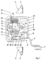
- the clamping pliers shown have a substantially rectangular, box-shaped and upwardly open housing 1 made of a plastic.
- the clamping pliers have a jaw 4 fastened to the housing base 2 with screws 3, a pivotably movable jaw 5 and an actuating lever 6.
- the plate-shaped jaws 4 and 5 are shown interrupted in Fig. 1 for clarity.
- the screws 3 can also serve to fasten the clamp on a chain conveyor, not shown.
- the lever 6 is provided with a roller 7 for its actuation by an external organ.
- the lever 6 is pivotally mounted on a shaft 8 arranged in the housing 1, specifically in a corner cutout 9 of the housing 1 (FIG. 1).
- the lever 6 is formed with two arms and on its lever arm 10 opposite the roller 7 has a shoulder 11 which comes to rest in the closed position of the clamping pliers on the inside of the base 2 (FIG. 3) and thus the pivoting movement of the lever 6 around the Shaft 8 limited in one pivot direction.
- the lever arm 10 is provided with a lug 12 having a bore.
- a bearing pin 13 is also arranged parallel to the shaft 8.
- the bearing pin 13 carries a first, on this rotatable sleeve part 14 and, axially separated from the sleeve part 14, a second, on the bearing pin 13 rotatable sleeve part 15.
- the two independently rotatable sleeve parts 14 and 15 are by a coaxial coil spring 16 (Fig. 1st ) connected to each other, the helical spring 16 being inserted at one end 17 into a lug 18 of the second sleeve part 15 and at its other end 19 (FIG. 1) into the first sleeve part 14.
- a second coaxial coil spring 20 is arranged as a return spring, which is inserted at one end 21 into a side wall 22 of the housing 1 and at its other end 23 into a nose 24 of the first sleeve part 14.
- the movable jaw 5 is firmly anchored to a projection 25 of the first sleeve part 14 (FIGS. 2, 3) by means of screws 26 (FIG. 2). It can thus be pivoted on the bearing pin 13 against the force of the helical spring 20 from the open position according to FIG. 2 to the closed position according to FIG. 3.
- the open position of the jaw 5 is limited in that the jaw 5 comes to rest on an upper housing edge 27 (FIGS. 2, 3).
- the lever 6 is connected to the second sleeve part 15 via a tab 28, the nose 12 of the lever arm 10 being rotatably mounted in a slot 29 of the tab 28 by means of a bolt 30.
- the other end of the tab 28 is mounted in a slot 31 of the nose 18 of the second sleeve part 15 by means of the end 17 of the coil spring 16.
- a rotary movement of the lever 6 thus causes a rotation of the second sleeve part 15 or a rotary movement of the helical spring 16 via the tab 28.
- the return spring 20 acts from the first sleeve part 14 via the first coil spring 16 and the tab 28 also on the lever 6 and holds it in the position shown in FIG. 2. Since the lever 6 is freely movable in this case is, the coil spring 16 is to be regarded as a quasi-rigid connection between the first sleeve part 14 and the lever 6.
- the helical spring 16 is twisted when the lever 6 is pivoted further in the direction of the arrow 32, that is to say tensioned since the first sleeve part 14 can no longer rotate.
- the counterforce now acting on the lever 6 is approximately equal to the force which the movable jaw 5 exerts on the fixed jaw 4, directly or via the object 34.
- the lever 6 is pivoted in a simple manner in the opposite direction to the arrow 32, the coil spring 16 first opening the movable jaw 5 and pressing the lever 6 downward and then the return spring 20 for a full opening, including the pivoting of the lever 6 in its position according to FIG. 2.
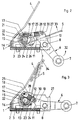
- FIGS. 4 to 6 The further embodiment of the clamping pliers according to the invention shown in FIGS. 4 to 6 makes use of another dead center mechanism, namely a locking curve instead of a knee joint.
- the clamping pliers in turn have an approximately rectangular, box-shaped housing 41 with a housing base 42, to which a clamping jaw 44, shown broken off in FIG. 4, is fastened by means of screws 43.
- a pivotably movable jaw 45 is wire-shaped.
- the clamping pliers again have a lever 46 for their actuation, which is provided with a roller 47.
- the lever 46 is connected to a first shaft 48 which is rotatably mounted in the housing 41 and which is subjected to the force of a coaxial restoring spring 49 which is supported on the housing base 42 and which thus rests the lever 46 in the position shown in FIG. 5 against a housing stop 50 presses.
- a second shaft 51 which is designed as a hollow shaft and, like the housing 41, is made of a plastic, is rotatably mounted.
- the shaft 51 is provided in the interior of the housing 41 with a longitudinal slot 52.
- the shaft 51 projects beyond it and is provided with an integrally formed lever arm 53.
- the lever arm 53 has a straight longitudinal groove 54 which is open at the radially outer end and has a sharp-angled bend 55 in its radially outer end region and a curvature 56 on the other side (FIGS. 5, 6).
- the lever 46 is provided on its side opposite the groove 54 with a roller 57 which is guided in the groove 54. A pivoting movement of the lever 46 thus causes the shaft 51 to rotate.
- the wire-shaped, movable jaw 45 is wound inside the housing 41 with its two side parts 58 and 59 around the shaft 51 and with its ends 60 and 61 in the slot 52 of the Shaft 51 inserted.
- the winding sections of the movable jaw 45 thus each form a helical spring 62 or 63, which connect the jaw 45 to the lever 46 via the shaft 51 and the lever arm 53.
Landscapes
- Engineering & Computer Science (AREA)
- Mechanical Engineering (AREA)
- Gripping Jigs, Holding Jigs, And Positioning Jigs (AREA)
- Discharge By Other Means (AREA)
- Chain Conveyers (AREA)
- Forklifts And Lifting Vehicles (AREA)
- Clamps And Clips (AREA)
- Manipulator (AREA)
- Feeding Of Articles By Means Other Than Belts Or Rollers (AREA)
Claims (8)
- Pince-étau pour transporteurs à chaîne, avec un boîtier (1 ; 41) qui peut être relié à la chaîne transporteuse et dans lequel sont disposés un premier mors de serrage (4 ; 44) et un second mors de serrage (5 ; 45), monté à pivotement et pouvant être déplacé, autour d'un premier axe (13 ; 51), contre le premier mors de serrage (4 ; 44) à partir d'une position ouverte, et avec un levier d'actionnement (6 ; 46), monté dans le boîtier (1 ; 41) et qui peut être pivoté, autour d'un second axe (8 ; 48) parallèle au premier axe (13 ; 51), entre deux positions finales qui correspondent respectivement à la position ouverte et à la position fermée du second mors de serrage (5 ; 45) par rapport au premier mors de serrage (4 ; 44), le levier d'actionnement (6 ; 46) entraînant, par une liaison en pivotement (29, 30 ; 54, 57), un autre levier (28 ; 53) qui transmet son mouvement de pivotement au second mors de serrage (5 ; 45) par l'intermédiaire d'un élément de ressort (16 ; 62, 63), serrant ainsi ce second mors pendant le mouvement de fermeture, caractérisée en ce que la liaison en pivotement (29, 30 ; 54, 57) entre les leviers (respectivement 6 ; 46 et 28 ; 53) passe par un point mort pendant la tension de l'élément de ressort (16 ; 62, 63), de telle sorte que l'élément de ressort (16 ; 62, 63), une fois le point mort dépassé, maintient bloqués le second mors de serrage (5 ; 45) et le levier d'actionnement (6 ; 46) dans la position fermée.
- Pince-étau selon la revendication 1, caractérisée en ce que le levier (28) est une patte qui est reliée de façon articulée au levier d'actionnement (6) par sa première extrémité et à l'élément de ressort (16) par son autre extrémité.
- Pince-étau selon la revendication 2, caractérisée en ce que le levier d'actionnement (6) est à deux bras, la patte (28) étant reliée de façon articulée au second bras de levier (10, 12).
- Pince-étau selon la revendication 2 ou 3, caractérisée en ce que le levier d'actionnement (6) est relié à un arbre (8), monté à rotation dans le boîtier (1) et constituant ledit second axe, en ce que le mors de serrage mobile (5) est monté à pivotement sur un pivot (13) constituant ledit premier axe, et en ce que l'élément de ressort est un ressort à boudin (16) disposé coaxialement au pivot (13) et possédant deux extrémités (17, 19) s'étendant dans la direction longitudinale du pivot (13), dont l'une (17) sert d'axe d'articulation pour la patte (28) et dont l'autre (19) est reliée en transmission de couple de rotation au mors de serrage mobile (5).
- Pince-étau selon la revendication 4, caractérisée en ce qu'un autre ressort à boudin (20) est disposé sur le pivot (13) comme ressort de rappel pour le mors de serrage mobile (5) et pour le levier d'actionnement (6).
- Pince-étau selon la revendication 1, caractérisée en ce que la liaison en pivotement (54, 57) présente une rainure (54), formant une piste de came déterminant le point mort et présentant de préférence un coudage anguleux (55), et une came (57) s'engageant dans la rainure (54).
- Pince-étau selon la revendication 6, caractérisée en ce que le levier d'actionnement (46) est lié en rotation à un premier arbre (48), monté dans le boîtier (41) et constituant ledit second axe, en ce que le levier (53) pourvu de la rainure (54) est formé sur un second arbre (51), monté dans le boîtier (41) et constituant ledit premier axe, et en ce que le mors de serrage mobile (45) est réalisé en fil d'acier, ses parties latérales (58, 59) s'étendant en direction du second arbre (51) étant enroulées en sens contraires autour du second arbre (51) sous la forme de ressorts à boudin (62, 63), et fixées au second arbre (51) par leurs extrémités (60, 61).
- Pince-étau selon la revendication 7, caractérisée en ce qu'un autre ressort à boudin (49) est disposé sur le premier arbre (48) comme ressort de rappel pour le levier d'actionnement (46) et pour le mors de serrage mobile (45).
Applications Claiming Priority (3)
| Application Number | Priority Date | Filing Date | Title |
|---|---|---|---|
| CH4023/89 | 1989-11-08 | ||
| CH402389 | 1989-11-08 | ||
| PCT/CH1990/000247 WO1991007342A1 (fr) | 1989-11-08 | 1990-10-22 | Pince-etau pour transporteurs a chaine |
Publications (2)
| Publication Number | Publication Date |
|---|---|
| EP0452434A1 EP0452434A1 (fr) | 1991-10-23 |
| EP0452434B1 true EP0452434B1 (fr) | 1994-07-20 |
Family
ID=4268376
Family Applications (1)
| Application Number | Title | Priority Date | Filing Date |
|---|---|---|---|
| EP90914891A Expired - Lifetime EP0452434B1 (fr) | 1989-11-08 | 1990-10-22 | Pince-etau pour transporteurs a chaine |
Country Status (6)
| Country | Link |
|---|---|
| US (1) | US5178262A (fr) |
| EP (1) | EP0452434B1 (fr) |
| JP (1) | JPH04502608A (fr) |
| AT (1) | ATE108746T1 (fr) |
| DE (1) | DE59006518D1 (fr) |
| WO (1) | WO1991007342A1 (fr) |
Families Citing this family (15)
| Publication number | Priority date | Publication date | Assignee | Title |
|---|---|---|---|---|
| RU2053184C1 (ru) * | 1990-08-06 | 1996-01-27 | Радуцкий Григорий Аврамович | Устройство для вывода газетной продукции из фальцаппарата рулонной ротационной машины |
| SE469889B (sv) * | 1992-03-16 | 1993-10-04 | Wamag Idab Ab | Griparetransportör med permanent förspänd klämback |
| SE469890B (sv) * | 1992-03-16 | 1993-10-04 | Wamag Idab Ab | Griparetransportör med permanent förspänd gripare |
| ATE127425T1 (de) * | 1992-12-01 | 1995-09-15 | Frisco Findus Ag | Greifvorrichtung. |
| DE59306510D1 (de) * | 1992-12-02 | 1997-06-26 | Ferag Ag | Greifer für eine Fördereinrichtung zum Fördern von ein- oder mehrblättrigen Druckereierzeugnissen |
| US5575379A (en) * | 1993-06-17 | 1996-11-19 | Gammerler Maschinenbau Und Anlagentechnik Gmbh | Newspaper conveyor |
| US5810347A (en) * | 1994-11-21 | 1998-09-22 | Heidelberger Druckmaschinen Ag | Apparatus for gripping and conveying sheet-like products |
| DE19642117A1 (de) | 1996-10-12 | 1998-04-16 | Koenig & Bauer Albert Ag | Klemmzange für Endlosförderer |
| US6336310B1 (en) * | 1998-09-08 | 2002-01-08 | Sanford Redmond | Method and apparatus for making compact packages for speadable product |
| US6227588B1 (en) * | 1999-02-17 | 2001-05-08 | Heidelberger Druckmaschinen Aktiengesellschaft | Gripper assembly |
| US6357741B1 (en) * | 2000-01-20 | 2002-03-19 | Heidelberger Druckmaschinen Ag | Velocity adjustable grippers on sliding carriage |
| US6925784B2 (en) * | 2003-09-11 | 2005-08-09 | The Procter & Gamble Company | Flexible manufacturing system for consumer packaged products |
| US7690635B2 (en) * | 2007-12-24 | 2010-04-06 | Pitney Bowes Inc. | Cam driven insert gripper |
| EP2840049B1 (fr) * | 2013-08-20 | 2017-05-10 | Harro Höfliger Verpackungsmaschinen GmbH | Dispositif de transport d'un prospectus |
| WO2019130316A1 (fr) * | 2018-01-01 | 2019-07-04 | Foldimate Inc. | Attache d'article pour plieuse, ensemble attache d'article et procédé d'introduction d'article pour plieuse |
Family Cites Families (12)
| Publication number | Priority date | Publication date | Assignee | Title |
|---|---|---|---|---|
| GB803027A (en) * | 1956-03-12 | 1958-10-15 | Roland Offsetmaschf | Improvements in or relating to sheet conveying mechanism of printing machines |
| US2940750A (en) * | 1957-11-26 | 1960-06-14 | Mestre Luis | Collating machine |
| FR2214292A5 (fr) * | 1973-01-16 | 1974-08-09 | Ctre Etud Tech Ind Habillement | |
| CH590778A5 (fr) * | 1975-10-08 | 1977-08-31 | Ferag Ag | |
| CH618398A5 (fr) * | 1977-06-06 | 1980-07-31 | Ferag Ag | |
| US4167996A (en) * | 1978-03-27 | 1979-09-18 | General Motors Corporation | Suspension type clamping transport hook |
| CH644816A5 (de) * | 1980-02-08 | 1984-08-31 | Ferag Ag | Foerdereinrichtung, inbesondere fuer druckprodukte, mit an einem umlaufenden zugorgan verankerten greifzangen. |
| US4681213A (en) * | 1985-10-23 | 1987-07-21 | Harris Graphics Corporation | Gripper assembly |
| US4746007A (en) * | 1986-02-20 | 1988-05-24 | Quipp Incorporated | Single gripper conveyor system |
| US4921294A (en) * | 1988-06-03 | 1990-05-01 | Am International Incorporated | Spring wire gripper jaw |
| CH677652A5 (fr) * | 1989-03-07 | 1991-06-14 | Grapha Holding Ag | |
| US4968081A (en) * | 1989-03-13 | 1990-11-06 | Hall Processing Systems | Non-contact actuator |
-
1990
- 1990-10-22 JP JP2513864A patent/JPH04502608A/ja active Pending
- 1990-10-22 WO PCT/CH1990/000247 patent/WO1991007342A1/fr not_active Ceased
- 1990-10-22 EP EP90914891A patent/EP0452434B1/fr not_active Expired - Lifetime
- 1990-10-22 AT AT90914891T patent/ATE108746T1/de not_active IP Right Cessation
- 1990-10-22 US US07/720,772 patent/US5178262A/en not_active Expired - Lifetime
- 1990-10-22 DE DE59006518T patent/DE59006518D1/de not_active Expired - Lifetime
Also Published As
| Publication number | Publication date |
|---|---|
| EP0452434A1 (fr) | 1991-10-23 |
| WO1991007342A1 (fr) | 1991-05-30 |
| ATE108746T1 (de) | 1994-08-15 |
| DE59006518D1 (de) | 1994-08-25 |
| US5178262A (en) | 1993-01-12 |
| JPH04502608A (ja) | 1992-05-14 |
Similar Documents
| Publication | Publication Date | Title |
|---|---|---|
| EP0452434B1 (fr) | Pince-etau pour transporteurs a chaine | |
| DE69801239T2 (de) | Greifer für Container, insbesondere für Flaschen | |
| DE69102158T2 (de) | Hautklammergerät mit rotierendem Kopf. | |
| DE10001580B4 (de) | Greifervorrichtung | |
| EP2493663B1 (fr) | Pince de montage avec cliquet d'arret libérable | |
| EP1765720B1 (fr) | Pince pour contenants et machine de manipulation de contenants | |
| DE2519561A1 (de) | Transporteur fuer in einem schuppenstrom anfallende druckprodukte mit an einem umlaufenden zugorgan in abstaenden verankerten greifern | |
| DE69313897T2 (de) | Förderer mit Greifern | |
| DE2439391B (de) | Ausschalter mit einem Schaltmechanismus und einem diesen steuernden Betätigungsmechanismus | |
| EP0124919B1 (fr) | Pince à pressage munie d'une pièce d'arrêt utilisée pour presser des souliers de câble | |
| DE69636639T2 (de) | Lastschalter | |
| EP1012099A1 (fr) | Dispositif de manipulation de pieces de manutention en forme de feuille | |
| DE1640268A1 (de) | Drehschalter mit einer Verriegelung fuer den Drehmechanismus | |
| EP1979112A1 (fr) | Dispositif de transport de pieces | |
| DE4446464A1 (de) | Schloß, insbesondere für Autotüren | |
| DE69313490T2 (de) | Greiferförderer | |
| DE19839252B4 (de) | Schaltmechanismus für Schutzschalter | |
| DE2934908A1 (de) | Leistungsschalter | |
| DE3823132C2 (de) | Treibstangenverschluß | |
| EP0586733A1 (fr) | Dispositif à action brusque pour interrupteurs électriques | |
| EP0370206B1 (fr) | Dispositif pour déposer des feuilles | |
| DE1900188A1 (de) | Sicherheitsvorrichtung zur UEberwachung des Bewegungsablaufes von Quertransportzangen an Mehrstufenpressen | |
| DE4131461C2 (de) | Maschine zum Öffnen von Bügelverschlußflaschen | |
| DE29803998U1 (de) | Zange | |
| DE19927728C1 (de) | Greifermechanismus für Einrichtungen zur Handhabung blattartiger oder plattenartiger Gegenstände, insbesondere für Postbearbeitungsmaschinen |
Legal Events
| Date | Code | Title | Description |
|---|---|---|---|
| PUAI | Public reference made under article 153(3) epc to a published international application that has entered the european phase |
Free format text: ORIGINAL CODE: 0009012 |
|
| 17P | Request for examination filed |
Effective date: 19910610 |
|
| AK | Designated contracting states |
Kind code of ref document: A1 Designated state(s): AT DE FR GB IT |
|
| 17Q | First examination report despatched |
Effective date: 19930505 |
|
| GRAA | (expected) grant |
Free format text: ORIGINAL CODE: 0009210 |
|
| AK | Designated contracting states |
Kind code of ref document: B1 Designated state(s): AT DE FR GB IT |
|
| REF | Corresponds to: |
Ref document number: 108746 Country of ref document: AT Date of ref document: 19940815 Kind code of ref document: T |
|
| REF | Corresponds to: |
Ref document number: 59006518 Country of ref document: DE Date of ref document: 19940825 |
|
| ET | Fr: translation filed | ||
| ITF | It: translation for a ep patent filed | ||
| GBT | Gb: translation of ep patent filed (gb section 77(6)(a)/1977) |
Effective date: 19940915 |
|
| PLBE | No opposition filed within time limit |
Free format text: ORIGINAL CODE: 0009261 |
|
| STAA | Information on the status of an ep patent application or granted ep patent |
Free format text: STATUS: NO OPPOSITION FILED WITHIN TIME LIMIT |
|
| 26N | No opposition filed | ||
| PGFP | Annual fee paid to national office [announced via postgrant information from national office to epo] |
Ref country code: FR Payment date: 19950922 Year of fee payment: 6 |
|
| PGFP | Annual fee paid to national office [announced via postgrant information from national office to epo] |
Ref country code: GB Payment date: 19951012 Year of fee payment: 6 |
|
| PGFP | Annual fee paid to national office [announced via postgrant information from national office to epo] |
Ref country code: AT Payment date: 19951030 Year of fee payment: 6 |
|
| PG25 | Lapsed in a contracting state [announced via postgrant information from national office to epo] |
Ref country code: GB Effective date: 19961022 Ref country code: AT Effective date: 19961022 |
|
| GBPC | Gb: european patent ceased through non-payment of renewal fee |
Effective date: 19961022 |
|
| PG25 | Lapsed in a contracting state [announced via postgrant information from national office to epo] |
Ref country code: FR Effective date: 19970630 |
|
| REG | Reference to a national code |
Ref country code: FR Ref legal event code: ST |
|
| PG25 | Lapsed in a contracting state [announced via postgrant information from national office to epo] |
Ref country code: IT Free format text: LAPSE BECAUSE OF NON-PAYMENT OF DUE FEES;WARNING: LAPSES OF ITALIAN PATENTS WITH EFFECTIVE DATE BEFORE 2007 MAY HAVE OCCURRED AT ANY TIME BEFORE 2007. THE CORRECT EFFECTIVE DATE MAY BE DIFFERENT FROM THE ONE RECORDED. Effective date: 20051022 |
|
| PGFP | Annual fee paid to national office [announced via postgrant information from national office to epo] |
Ref country code: DE Payment date: 20091221 Year of fee payment: 20 |
|
| PG25 | Lapsed in a contracting state [announced via postgrant information from national office to epo] |
Ref country code: DE Free format text: LAPSE BECAUSE OF EXPIRATION OF PROTECTION Effective date: 20101022 |