EP0452443B1 - Tete rotative d'analyse d'echantillon de produit metallique - Google Patents
Tete rotative d'analyse d'echantillon de produit metallique Download PDFInfo
- Publication number
- EP0452443B1 EP0452443B1 EP90915452A EP90915452A EP0452443B1 EP 0452443 B1 EP0452443 B1 EP 0452443B1 EP 90915452 A EP90915452 A EP 90915452A EP 90915452 A EP90915452 A EP 90915452A EP 0452443 B1 EP0452443 B1 EP 0452443B1
- Authority
- EP
- European Patent Office
- Prior art keywords
- eddy current
- rotary head
- magnetic flux
- head according
- rotary
- Prior art date
- Legal status (The legal status is an assumption and is not a legal conclusion. Google has not performed a legal analysis and makes no representation as to the accuracy of the status listed.)
- Expired - Lifetime
Links
- 239000002184 metal Substances 0.000 title description 3
- 229910052751 metal Inorganic materials 0.000 title description 3
- 238000012360 testing method Methods 0.000 claims abstract description 55
- 239000000463 material Substances 0.000 claims abstract description 41
- 230000005291 magnetic effect Effects 0.000 claims abstract description 35
- 230000004907 flux Effects 0.000 claims abstract description 25
- 230000001681 protective effect Effects 0.000 claims description 28
- 239000004020 conductor Substances 0.000 claims description 11
- 238000011156 evaluation Methods 0.000 claims description 3
- 230000005294 ferromagnetic effect Effects 0.000 abstract description 6
- 238000000926 separation method Methods 0.000 abstract description 2
- 238000005336 cracking Methods 0.000 abstract 1
- 239000007769 metal material Substances 0.000 abstract 1
- 230000007547 defect Effects 0.000 description 7
- 239000000523 sample Substances 0.000 description 6
- 238000000265 homogenisation Methods 0.000 description 5
- 230000005415 magnetization Effects 0.000 description 4
- 229910000831 Steel Inorganic materials 0.000 description 3
- 239000003302 ferromagnetic material Substances 0.000 description 3
- 239000012811 non-conductive material Substances 0.000 description 3
- 230000035699 permeability Effects 0.000 description 3
- 230000035945 sensitivity Effects 0.000 description 3
- 239000010959 steel Substances 0.000 description 3
- 238000004804 winding Methods 0.000 description 3
- 230000005540 biological transmission Effects 0.000 description 2
- 230000005284 excitation Effects 0.000 description 2
- 239000012535 impurity Substances 0.000 description 2
- 230000035515 penetration Effects 0.000 description 2
- 238000005299 abrasion Methods 0.000 description 1
- 230000002411 adverse Effects 0.000 description 1
- 230000000295 complement effect Effects 0.000 description 1
- 230000001066 destructive effect Effects 0.000 description 1
- 238000001514 detection method Methods 0.000 description 1
- 238000011161 development Methods 0.000 description 1
- 230000009977 dual effect Effects 0.000 description 1
- -1 ferrous metals Chemical class 0.000 description 1
- 238000010438 heat treatment Methods 0.000 description 1
- 239000011810 insulating material Substances 0.000 description 1
- 238000012545 processing Methods 0.000 description 1
- 230000000717 retained effect Effects 0.000 description 1
- 238000005096 rolling process Methods 0.000 description 1
- 229920006395 saturated elastomer Polymers 0.000 description 1
- 238000005482 strain hardening Methods 0.000 description 1
- 238000004154 testing of material Methods 0.000 description 1
- 238000012549 training Methods 0.000 description 1
- 230000007704 transition Effects 0.000 description 1
- 238000003466 welding Methods 0.000 description 1
- 229910000859 α-Fe Inorganic materials 0.000 description 1
Images


Classifications
-
- G—PHYSICS
- G01—MEASURING; TESTING
- G01N—INVESTIGATING OR ANALYSING MATERIALS BY DETERMINING THEIR CHEMICAL OR PHYSICAL PROPERTIES
- G01N27/00—Investigating or analysing materials by the use of electric, electrochemical, or magnetic means
- G01N27/72—Investigating or analysing materials by the use of electric, electrochemical, or magnetic means by investigating magnetic variables
- G01N27/82—Investigating or analysing materials by the use of electric, electrochemical, or magnetic means by investigating magnetic variables for investigating the presence of flaws
- G01N27/90—Investigating or analysing materials by the use of electric, electrochemical, or magnetic means by investigating magnetic variables for investigating the presence of flaws using eddy currents
- G01N27/9013—Arrangements for scanning
Definitions
- the invention relates to a rotating head for scanning the surface of elongated metallic test material by eddy current sensors according to the preamble of claim 1.
- Rotating heads of this type have long been known in non-destructive material testing, see for example US-A-4,596,953 or DE-A-29 05 399 and are used in many different ways. They are used there to check, in particular, bright round material made of steel and non-ferrous metals for defects that reach the surface. Over the long period of use, these rotary heads have reached a high level of development, which enables them to perform well. For example, For bare surfaces, reliably detect cracks with a depth of only 30 micrometers and this at very high throughput speeds. On the other hand, boundaries are recognizable, which it would be desirable to exceed because they would open up new areas of application.
- a sensitive test of "not bright" ferromagnetic steel with the currently known eddy current rotating heads is not possible because of the high material-related interference level.
- Another example concerns cracks in ferromagnetic material, in which subsequent processing, such as rolling, drawing or peeling, again creates a closed surface above the material separation.
- it is the low penetration depth of the eddy currents at the high frequencies required for the desired sensitivity, which makes it impossible to display such "smeared" cracks in most cases.
- Another borderline case is the testing of welded austenitic pipes, where ferritic impurities cause a high level of interference in the area of the weld seam and in this way prevent an effective test of the latter.
- US-A-3,299,349 also discloses a test head for scanning the surface of elongated test material with two magnetization coils for magnetizing the test material and with sensor coils distributed between the magnetization coils around the circumference of the test material, which detect the leakage flow at defects in the material surface of the test material caused by the Ring is moved through by sensor coils, detect.
- the invention has for its object to improve the rotary head of the type defined in such a way that its use in the above-mentioned and in other cases is possible.
- the magnetization of the test material made possible by the solution according to the invention results in a substantial reduction in the magnetic permeability of the test material in the intended test area, in particular if it is possible to reach the saturation area.
- the ferrite cores of the eddy current generators will also become saturated and that the sensitivity of the latter will be adversely affected.
- This is counteracted by the ring made of magnetically conductive material, which is arranged between the magnetizing coil and the eddy current sensors. It homogenizes the magnetic field in the test area and causes the radial component of the magnetic field above the surface of the test part to remain small.
- An embodiment of the invention provides that exchangeable protective sockets carried by the housing and having a bore that can be adapted to the diameter of the test material serve as a magnetic flux conductor.
- a protective bush protrudes into the bore of the hollow shaft so that the magnetic flux can be optimally conducted into the test material via the rotating hollow shaft.
- Another embodiment provides the suggestion that there is a narrow air gap at least at one point between the protective bushing and the hollow shaft, so that a low-loss transmission of the magnetic flux is possible.
- the homogenization ring covers the side of the magnetizing coil facing the eddy current sensors up to a distance from the axis of rotation which corresponds to approximately twice the maximum radial distance of the eddy current sensors from the axis of rotation.
- An important aspect of the invention is that the homogenization ring is in a magnetically conductive connection with the parts of the housing which conduct the magnetic flux.
- the protective bushings are completely or partially lined with a thin layer of magnetically non-conductive material. This prevents magnetized ferromagnetic test material from "sticking" to the protective sockets and ensures easy passage through the latter.
- the rotating part has a rotating disk fixedly connected to the hollow shaft, on which the eddy current sensors are suspended, and which consists of magnetically non-conductive material. This prevents magnetic poles from forming on the disk and causing eddy currents in adjacent housing parts, which would result in heating and braking.
- An essential aspect of the invention is that in the test area penetrated by the magnetic field, a fixed eddy current generator arrangement is additionally installed, which may have found its place inside a protective socket. As a result, the space and effort-saving combination of fixed and rotating eddy current sensors made possible in a simple manner. It proves to be particularly advantageous that both can use the same DC bias to reduce the interference level.
- the fixed eddy current generator arrangement can be both absolute and differential continuous coils.
- segment coils distributed over the circumference can also be provided.
- absolute coils can now also detect material mix-ups. Differential continuous coils are particularly suitable for the resolution of external transverse defects, hole defects in pipes and foreign material inclusions. The various systems can ideally complement each other.
- stray flux coils can also be used in the case of ferromagnetic material instead of the eddy current feed-through coils. These are constructed similarly or identically to the eddy current moving coils, in fact the same coils can be used for the simultaneous reception of eddy current and leakage flux signals.
- DC biasing has the additional task of generating a magnetic stray flux at fault locations which is picked up by the above-mentioned coils. This results in a further reduction in the detection limit for cross cracks.
- internal defects can also be detected. Local wall constrictions can be tracked down.
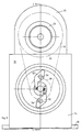
- a rotating head is shown in a section or in front view.
- a housing 10 which is composed of a base plate 12, walls 14, a housing plate 16, a cover plate 18, bars 20, a receiving body 22 and a bearing body 24 forms the load-bearing component of the rotating head.
- the aforementioned parts of the housing 10 are made of ferromagnetic steel and connected to one another by welding or other suitable means.
- the cover plate 18 carries a drive motor 26 which is secured by a flange plate 28. The rotational movement of the motor 26 is transmitted from a drive shaft 30 to a drive wheel 32, which is protected against access by a cover 34.
- a drive belt 36 transmits the drive force to a drive wheel 38 rigidly connected to a hollow shaft 40.
- the hollow shaft 40 is supported on the bearing body 24 by two suitable ball bearings 42, which are supported against one another via a ferromagnetic support bushing 44 and by fastening rings 46 and 48 on the hollow shaft 40 and are fixed on the bearing body 24.
- the air gap between the latter and the support sleeve 44 is narrow, so that the magnetic flux experiences the least possible impediment during the transition from one to the other.
- a rotating disk 50 made of light metal is rigidly fixed to the hollow shaft 40. Together with the hollow shaft 40 and the drive wheel 38, it forms the rotating part 51.
- Two probe levers 52 are pivotably supported by bolts 54 and about the latter in bearing blocks 56 which are fastened to the rotating disk 50. For the sake of clarity, only one of the two probe levers 52 is shown in FIG. 1.
- a probe bar 58 is attached, which carries five eddy current generators 60 each. In operation, these are located in the immediate vicinity of the surface of the test material and scan them in spiral paths when the test object passes through the rotating head with rotating part 51.
- a rod 62 leaving the rotating head in the direction of arrow 61 is shown in FIG.
- the signals of the rotating Eddy current generators 60 reach the outside via a rotary transformer arrangement 64 and are connected via a cable to an electronic evaluation device (both not shown).
- the rotary transformer arrangement can be one as is described in detail in the parallel application P 36 32 395.
- a rotor disk 66 and a stator disk 68 It consists of a rotor disk 66 and a stator disk 68, the former rigidly connected to the hollow shaft 40 and secured by a bushing 70, the latter fastened to the receiving body 22 via a support plate 72 and arranged in close proximity to the rotating disk 66.
- the outputs of the eddy current generators 60 are connected to primary windings 74 embedded in the rotor disk 66, while secondary windings 76 embedded in the stator disk 68 are led to the above-mentioned cable via a plug connection (not shown).
- the housing plate 16 which is omitted in FIG. 2 due to the view of the probe levers 52, has a dual function. On the one hand, it closes the opening in the front wall 14 except for a passage 78 for the test material 62, and on the other hand it offers space for accommodating a magnetizing coil 80. This can be produced as a self-supporting winding, which is in the space provided in the housing plate 16 is inserted and is held by a homogenization ring 82. An additional meaning of the homogenization ring 82 is reported further below.
- a front protective bushing 84 is inserted into the passage 78 of the housing plate 16.
- a rear protective bush 86 is fastened to the rear wall 14 and projects into the bore of the hollow shaft 40.
- the task of the two protective sockets 84, 86 is to safely guide the test material 62 and to protect the sensitive eddy current sensors 60 from damage by incoming test material.
- the protective sockets 84, 86 which are made of magnetically conductive material, make an important contribution to the transmission of the magnetic flux.
- the rear protective sleeve 86 has a limited end at its front end Area with a slightly smaller diameter than that of the bore of the hollow shaft 40, so that here a narrow air gap 88 with a small magnetic resistance is created.
- the protective bushings 84, 86 are interchangeable and are available with a closely staggered selection of bores.
- the magnetic flux generated in the magnetizing coil 80 takes its way via the housing plate 16, front wall 14, base plate 12 or cover plate 18 or the side walls, via the spars 20, receiving body 22, bearing body 24, support sleeve 44 and hollow shaft 40.
- the direct introduction of the magnetic flux into the test material 62 takes place via the protective sockets 84, 86.
- the bores of the protective bushings 84, 86 are each lined with a thin layer of magnetically non-conductive material.
- abrasion-resistant sleeves 90 and 92 are provided. The result of this is that magnetized ferromagnetic test material does not "stick" inside the protective bushings 84, 86 and can be pulled through the rotating head without great resistance.
- the test area in which the test material 62 is fully magnetized is essentially limited by the ends of the two protective sockets 84, 86.
- the magnetic flux in the test area should be as homogeneous as possible and in particular should be in the space above the test material 62, where the eddy current sensors 60 are located, the radial component of the magnetic field are within narrow limits.
- FIG. 3 relates to the case where, in addition to the rotating eddy current sensors 60, stationary eddy current sensors are used in the test area.
- the front protective bush has undergone a different training for this. Since all other parts of the rotary head are retained unchanged, only one such protective bush 100, installed in the housing plate 16, is shown. As described above, the latter can be used in a rotating head according to FIGS. 1 and 2.
- the protective socket 100 is turned deeper on the right side.
- the fixed eddy current generator arrangement 102 is accommodated in the vacated space.
- This has a coil former 104 made of a suitable insulating material. There are three slots in the bottom of the coil former 104, in which eddy current receiver coils 106, 108 are inserted.
- the middle one can be an absolute coil 106, while the two outer ones (108) can be connected in difference.
- An eddy current excitation coil 112 is wound on the receiver coils 106, 108 and separated from them by an insulating layer 110.
- Lead wires 114 connect the receiver coils 106, 108 and the excitation coil 112 to a junction box 116, which enables the connection of the fixed eddy current generator arrangement 102 to an electronic evaluation unit.
- the protective bush 100 is also protected by a thin sleeve 118 against magnetic "sticking".
- a set of eddy current segment coils distributed over the circumference can also be installed in the space provided for them in the protective socket 100. It is also possible to use the transmitter arrangement 102 described as a leakage flux transmitter.
- the magnetic flux in the test material 62 caused by the magnetizing coil 80 calls at fault locations magnetic stray fluxes. These can be picked up by coil 106, for example, and processed further in a known manner.
Landscapes
- Chemical & Material Sciences (AREA)
- Chemical Kinetics & Catalysis (AREA)
- Electrochemistry (AREA)
- Physics & Mathematics (AREA)
- Health & Medical Sciences (AREA)
- Life Sciences & Earth Sciences (AREA)
- Analytical Chemistry (AREA)
- Biochemistry (AREA)
- General Health & Medical Sciences (AREA)
- General Physics & Mathematics (AREA)
- Immunology (AREA)
- Pathology (AREA)
- Investigating Or Analyzing Materials By The Use Of Magnetic Means (AREA)
Abstract
Claims (10)
- Tête rotative pour explorer, à l'aide de générateurs de courants de Foucault (60), la surface d'un produit métallique (62) de forme allongée devant être contrôlé, comprenant un boîtier (10), une partie tournante (51), à laquelle sont fixés les générateurs de courants de Foucault (60) et qui comporte un arbre creux (40) convenant pour le passage du produit à contrôler (62) et monté rotatif sur le boîtier (10), des moyens d'entraînement (26) pour produire le mouvement rotatif de la partie tournante (51), ainsi qu'un système rotatif de transmission (64), à travers duquel les générateurs de courants de Foucault (60) sont reliés électriquement à une unité électronique d'exploitation, caractérisée en ce
que des moyens d'aimantation sont mis à disposition pour aimanter le produit (62) dans le sens de sa longueur à l'intérieur d'une zone de contrôle prévue à cet effet, moyens qui comprennent une bobine d'aimantation (80) qui entoure le produit (62) et est destinée à générer un flux magnétique, de même que des conducteurs de flux magnétique qui introduisent le flux magnétique dans le produit (62) à contrôler,
que l'on utilise, en tant que conducteurs de flux magnétique, des parties du boîtier (10) dimensionnées en conséquence et l'arbre creux (40), lesquels sont faits de matériau magnétiquement conducteur, et que, pour homogénéiser le champ magnétique dans la zone de contrôle, un anneau d'homogénéisation (82) en matériau conducteur magnétique, anneau qui entoure le produit (62) dans la zone de contrôle, est placé entre la bobine d'aimantation (80) et les générateurs de courants de Foucault (60). - Tête rotative selon la revendication 1, caractérisée en ce que des manchons protecteurs (84, 86, 100) interchangeables en matériau conducteur magnétique et dont le perçage est adaptable au diamètre du produit (62) à contrôler, servent également de conducteurs de flux magnétique, ces manchons étant portés par le boîtier (10).
- Tête rotative selon la revendication 2, caractérisée en ce que l'un des manchons protecteurs (86) fait saillie dans le perçage de l'arbre creux (40).
- Tête rotative selon la revendication 3, caractérisée en ce qu'un entrefer étroit (88) pour la transmission du flux magnétique est prévu à au moins un endroit entre le manchon protecteur (86) et l'arbre creux (40).
- Tête rotative selon une des revendications précédentes, caractérisée en ce que l'anneau d'homogénéisation (82) recouvre le côté dirigé vers les générateurs de courants de Foucault (60) de la bobine d'aimantation (80) jusqu'à une distance de l'axe de rotation qui correspond à peu près au double de la distance radiale maximale séparant les générateurs de courants de Foucault (60) de l'axe de rotation.
- Tête rotative selon une des revendications précédentes, caractérisée en ce que l'anneau d'homogénéisation (82) est en liaison magnétique conductrice avec les parties du boîtier (10) conduisant le flux magnétique.
- Tête rotative selon une des revendications précédentes, caractérisée en ce que les manchons protecteurs (84, 86, 100) sont revêtus entièrement ou partiellement, dans leur perçage , d'une mince couche (90, 92, 118) de matériau non conducteur magnétique.
- Tête rotative selon une des revendications précédentes, caractérisée en ce que la partie tournante (51) comporte un disque tournant (50) relié rigidement à l'arbre creux (40), disque auquel sont suspendus les générateurs de courants de Foucault (60) et qui est fait d'un matériau non conducteur magnétique.
- Tête rotative selon une des revendications précédentes, caractérisée en ce qu'un système stationnaire de générateurs de courants de Foucault (102) est monté en plus dans la zone de contrôle traversée du flux magnétique.
- Tête rotative selon la revendication 9, caractérisée en ce que le système stationnaire de générateurs de courants de Foucault (102) est monté à l'intérieur d'un manchon protecteur (100).
Applications Claiming Priority (2)
| Application Number | Priority Date | Filing Date | Title |
|---|---|---|---|
| DE3937261A DE3937261C2 (de) | 1989-11-09 | 1989-11-09 | Rotierkopf zum Abtasten von metallischem Prüfgut |
| DE3937261 | 1989-11-09 |
Publications (2)
| Publication Number | Publication Date |
|---|---|
| EP0452443A1 EP0452443A1 (fr) | 1991-10-23 |
| EP0452443B1 true EP0452443B1 (fr) | 1994-03-09 |
Family
ID=6393158
Family Applications (1)
| Application Number | Title | Priority Date | Filing Date |
|---|---|---|---|
| EP90915452A Expired - Lifetime EP0452443B1 (fr) | 1989-11-09 | 1990-10-10 | Tete rotative d'analyse d'echantillon de produit metallique |
Country Status (5)
| Country | Link |
|---|---|
| US (1) | US5187435A (fr) |
| EP (1) | EP0452443B1 (fr) |
| JP (1) | JPH0785075B2 (fr) |
| DE (1) | DE3937261C2 (fr) |
| WO (1) | WO1991007656A1 (fr) |
Families Citing this family (9)
| Publication number | Priority date | Publication date | Assignee | Title |
|---|---|---|---|---|
| DE4141257C2 (de) * | 1991-12-14 | 1996-08-29 | Foerster Inst Dr Friedrich | Vorrichtung zum Schutz einer mit mindestens einem Prüfkopf versehenen Prüfvorrichtung |
| DE4314274C2 (de) * | 1993-04-30 | 1995-11-30 | Foerster Inst Dr Friedrich | Verfahren und Vorrichtung zur automatischen Durchmesserverstellung von an einem rotierend angetriebenen Prüfkopf vorgesehenen Gebern von Meß- und/oder Prüfeinrichtungen |
| DE4339720A1 (de) * | 1993-11-22 | 1995-05-24 | Abb Management Ag | Verfahren zur Prüfung von Schweißnähten mittels Wirbelstromverfahren |
| RO111306B (ro) | 1994-12-14 | 1996-08-30 | Inst De Fizica Tehnica | Traductor pentru controlul produselor metalurgice, cilindrice, conductoare |
| DK1105721T3 (da) * | 1999-06-15 | 2007-07-02 | Georgsmarienhuette Gmbh | Valsemölle |
| DE102004015733A1 (de) * | 2004-03-29 | 2005-10-27 | Volkswagen Ag | Verfahren zur zerstörungsfreien Prüfung von Schweißnähten |
| DE202005003685U1 (de) * | 2005-03-08 | 2005-10-13 | Zindler, Pascale Mignard | Technische Neuerungen im Magnetkreis des Hochenergiewechselfeldjochs |
| DE102005061273A1 (de) | 2005-12-20 | 2007-06-21 | Prüftechnik Dieter Busch AG | Rotierkopf für zerstörungsfreie Prüfungen |
| US8806950B2 (en) | 2011-11-09 | 2014-08-19 | The Boeing Company | Electromagnetic acoustic transducer system |
Family Cites Families (19)
| Publication number | Priority date | Publication date | Assignee | Title |
|---|---|---|---|---|
| US3299349A (en) * | 1964-02-28 | 1967-01-17 | Plastic Applicators | Magnetic pipe inspection device with pivotally mounted sensor means |
| US3336527A (en) * | 1965-05-03 | 1967-08-15 | Magnaflux Corp | Spinning probe inspection device including retraction means disabled by centrifugal force |
| JPS4996785A (fr) * | 1973-01-16 | 1974-09-12 | ||
| GB1530454A (en) * | 1975-05-13 | 1978-11-01 | British Steel Corp | Rotary ultrasonic testing apparatus |
| JPS5940265B2 (ja) * | 1978-02-13 | 1984-09-28 | 日本鋼管株式会社 | 熱ビレツト渦流探傷装置 |
| JPS5739113A (en) * | 1980-08-20 | 1982-03-04 | Nippon Kokan Kk <Nkk> | Steel-making process by converter |
| US4507610A (en) * | 1981-07-30 | 1985-03-26 | Shimadzu Corporation | Apparatus for electromagnetically detecting flaws in metallic objects |
| DE3142459C2 (de) * | 1981-10-27 | 1986-07-17 | Institut Dr. Friedrich Förster Prüfgerätebau GmbH & Co KG, 7410 Reutlingen | Wirbelstromgeberanordnung |
| US4596953A (en) * | 1982-04-14 | 1986-06-24 | Daidotokushuko Kabushikikaisha | Apparatus for scanning a material for detection of flaws and having material axis deviation detection |
| US4449411A (en) * | 1982-04-22 | 1984-05-22 | Magnetic Analysis Corporation | Magnetic and ultrasonic objects testing apparatus |
| US4482865A (en) * | 1982-06-04 | 1984-11-13 | United States Steel Corporation | Apparatus for the automatic inducement of a magnetic field in an elongated article under test |
| JPS58218644A (ja) * | 1982-06-14 | 1983-12-19 | Sumitomo Metal Ind Ltd | 金属材料の表面疵探傷方法及びその装置 |
| US4641092A (en) * | 1982-07-08 | 1987-02-03 | Sumitomo Metal Industries, Ltd. | Rotary probe apparatus for detecting flaws in a test object |
| US4673879A (en) * | 1984-06-27 | 1987-06-16 | Rupublic Steel Corporation | Eddy current flaw detector having rotatable field defining sleeve for selectively enhancing induced eddy currents in a workpiece |
| DE3500011C2 (de) * | 1985-01-02 | 1986-04-17 | Axel R. Dr.-Ing. 5900 Siegen Hidde | Verfahren zur geregelten Entmagnetisierung stabförmiger, ferromagnetischer und vergüteter Halb- oder Fertigfabrikate im laufenden Produktionsprozeß |
| DE3603153A1 (de) * | 1986-02-01 | 1987-08-06 | Nukem Gmbh | Anordnung fuer die zerstoerungsfreie pruefung von zylinderfoermigen werkstuecken |
| DE3739190A1 (de) * | 1987-11-19 | 1989-06-01 | Foerster Inst Dr Friedrich | Rotierkopf zum abtasten der oberflaeche zylindrischer pruefteile |
| DE3743521A1 (de) * | 1987-12-22 | 1989-07-06 | Foerster Inst Dr Friedrich | Vorrichtung zum pruefen von halbzeug |
| JPH02221857A (ja) * | 1989-02-22 | 1990-09-04 | Hara Denshi Sokki Kk | 回転式漏洩磁束探傷機の回転ヘッド機構 |
-
1989
- 1989-11-09 DE DE3937261A patent/DE3937261C2/de not_active Expired - Fee Related
-
1990
- 1990-10-10 US US07/721,468 patent/US5187435A/en not_active Expired - Fee Related
- 1990-10-10 WO PCT/EP1990/001696 patent/WO1991007656A1/fr not_active Ceased
- 1990-10-10 JP JP2514405A patent/JPH0785075B2/ja not_active Expired - Fee Related
- 1990-10-10 EP EP90915452A patent/EP0452443B1/fr not_active Expired - Lifetime
Also Published As
| Publication number | Publication date |
|---|---|
| US5187435A (en) | 1993-02-16 |
| DE3937261A1 (de) | 1991-05-16 |
| JPH0785075B2 (ja) | 1995-09-13 |
| JPH03505134A (ja) | 1991-11-07 |
| WO1991007656A1 (fr) | 1991-05-30 |
| DE3937261C2 (de) | 1996-04-11 |
| EP0452443A1 (fr) | 1991-10-23 |
Similar Documents
| Publication | Publication Date | Title |
|---|---|---|
| DE3789848T2 (de) | Magnetischer Streuflussfühler zur zerstörungsfreien Prüfung. | |
| EP0322552B1 (fr) | Dispositif de test de demi-produits | |
| DE69429776T2 (de) | Detektion von rissen durch eine elektromagnetische transientendiffusionsinspektionsmethode | |
| DE4416252B4 (de) | Verfahren und Vorrichtung zur zerstörungsfreien magnetischen Prüfung von länglichen Objekten auf strukturelle Fehler | |
| DE3327762C2 (de) | Vorrichtung und Verfahren zum Messen der Wanddicke eines ferromagnetischen Elementes | |
| DE2600206A1 (de) | Wirbelstromgenerator zur materialpruefung | |
| DE102008020194A1 (de) | Verfahren und Vorrichtung zum Detektieren von oberflächennahen Defekten mittels Streuflussmessung | |
| DE1648358A1 (de) | Verfahren und Geraet zur Bestimmung von Unstetigkeitsstellen in elektrisch leitenden Materialien | |
| EP0452443B1 (fr) | Tete rotative d'analyse d'echantillon de produit metallique | |
| EP0458425A2 (fr) | Transducteur électromagnétique à aimant permanent | |
| EP0814321B1 (fr) | Capteur inductif de déplacement | |
| DE4344327A1 (de) | Wirbelstrom-Induktionssonde zur Feststellung von Rissen und Verfahren zur Prüfung von Metallblech auf Risse | |
| DE2448153B2 (de) | Wirbelstromsonde zur Innenuntersuchung von Rohren aus ferromagnetischen Materialien | |
| DE3314376A1 (de) | Vorrichtung zur zerstoerungsfreien materialpruefung | |
| DE69606626T2 (de) | Verfahren und vorrichtung zum kontrolle von röhren mittels wirbelströmen | |
| DE19623236A1 (de) | Verfahren und Vorrichtung für die Drehzahlmessung an Turboladern | |
| DE2440915C3 (de) | Wirbelstromprüfgerät | |
| DE112011104961B4 (de) | Als Gradiometer ausgestalterer Induktiver Sensor | |
| DE1648357A1 (de) | Verfahren und Geraet zur Materialpruefung durch induzierte Wirbelstroeme | |
| EP1701156B1 (fr) | Dispositif destiné à la vérification de défauts de surface sur un échantillon à l'aide d'un moyen de magnétisation et à l'aide de sondes à induction en tant que capteurs de mesure | |
| DE1573777A1 (de) | Geraet zur Inspektion von Metallgegenstaenden | |
| EP0040673B1 (fr) | Dispositif pour le soudage à l'arc électrique | |
| DE2506248C3 (de) | Wirbelstromprüfgerät für die zerstörungsfreie Prüfung von Gegenständen | |
| EP0465624A1 (fr) | Debitmetre inductif. | |
| DE4210689C2 (de) | Meßsonde zur Schichtdickenmessung |
Legal Events
| Date | Code | Title | Description |
|---|---|---|---|
| PUAI | Public reference made under article 153(3) epc to a published international application that has entered the european phase |
Free format text: ORIGINAL CODE: 0009012 |
|
| 17P | Request for examination filed |
Effective date: 19910629 |
|
| AK | Designated contracting states |
Kind code of ref document: A1 Designated state(s): FR GB SE |
|
| 17Q | First examination report despatched |
Effective date: 19930716 |
|
| GRAA | (expected) grant |
Free format text: ORIGINAL CODE: 0009210 |
|
| AK | Designated contracting states |
Kind code of ref document: B1 Designated state(s): FR GB SE |
|
| ET | Fr: translation filed | ||
| GBT | Gb: translation of ep patent filed (gb section 77(6)(a)/1977) |
Effective date: 19940412 |
|
| PLBE | No opposition filed within time limit |
Free format text: ORIGINAL CODE: 0009261 |
|
| STAA | Information on the status of an ep patent application or granted ep patent |
Free format text: STATUS: NO OPPOSITION FILED WITHIN TIME LIMIT |
|
| EAL | Se: european patent in force in sweden |
Ref document number: 90915452.8 |
|
| 26N | No opposition filed | ||
| PGFP | Annual fee paid to national office [announced via postgrant information from national office to epo] |
Ref country code: GB Payment date: 19960919 Year of fee payment: 7 |
|
| PG25 | Lapsed in a contracting state [announced via postgrant information from national office to epo] |
Ref country code: GB Free format text: LAPSE BECAUSE OF NON-PAYMENT OF DUE FEES Effective date: 19971010 |
|
| GBPC | Gb: european patent ceased through non-payment of renewal fee |
Effective date: 19971010 |
|
| PGFP | Annual fee paid to national office [announced via postgrant information from national office to epo] |
Ref country code: FR Payment date: 20021017 Year of fee payment: 13 |
|
| PGFP | Annual fee paid to national office [announced via postgrant information from national office to epo] |
Ref country code: SE Payment date: 20021023 Year of fee payment: 13 |
|
| PG25 | Lapsed in a contracting state [announced via postgrant information from national office to epo] |
Ref country code: SE Free format text: LAPSE BECAUSE OF NON-PAYMENT OF DUE FEES Effective date: 20031011 |
|
| EUG | Se: european patent has lapsed | ||
| PG25 | Lapsed in a contracting state [announced via postgrant information from national office to epo] |
Ref country code: FR Free format text: LAPSE BECAUSE OF NON-PAYMENT OF DUE FEES Effective date: 20040630 |
|
| REG | Reference to a national code |
Ref country code: FR Ref legal event code: ST |