EP0452494A1 - Chalumeau a plasma a arc transfere - Google Patents
Chalumeau a plasma a arc transfere Download PDFInfo
- Publication number
- EP0452494A1 EP0452494A1 EP90900362A EP90900362A EP0452494A1 EP 0452494 A1 EP0452494 A1 EP 0452494A1 EP 90900362 A EP90900362 A EP 90900362A EP 90900362 A EP90900362 A EP 90900362A EP 0452494 A1 EP0452494 A1 EP 0452494A1
- Authority
- EP
- European Patent Office
- Prior art keywords
- nozzle
- arc torch
- chamber
- plasma arc
- transferred plasma
- Prior art date
- Legal status (The legal status is an assumption and is not a legal conclusion. Google has not performed a legal analysis and makes no representation as to the accuracy of the status listed.)
- Granted
Links
- 238000011144 upstream manufacturing Methods 0.000 claims abstract description 3
- 230000004323 axial length Effects 0.000 claims description 4
- 239000007789 gas Substances 0.000 description 29
- 230000000694 effects Effects 0.000 description 7
- 238000009826 distribution Methods 0.000 description 5
- 238000013016 damping Methods 0.000 description 2
- 238000006073 displacement reaction Methods 0.000 description 2
- 238000003483 aging Methods 0.000 description 1
- 230000032683 aging Effects 0.000 description 1
- 239000000498 cooling water Substances 0.000 description 1
- 238000010586 diagram Methods 0.000 description 1
- 238000002474 experimental method Methods 0.000 description 1
- 239000012530 fluid Substances 0.000 description 1
- 238000011835 investigation Methods 0.000 description 1
- 238000005259 measurement Methods 0.000 description 1
- 239000002184 metal Substances 0.000 description 1
- 239000001301 oxygen Substances 0.000 description 1
- 229910052760 oxygen Inorganic materials 0.000 description 1
- 230000000717 retained effect Effects 0.000 description 1
Images


Classifications
-
- B—PERFORMING OPERATIONS; TRANSPORTING
- B23—MACHINE TOOLS; METAL-WORKING NOT OTHERWISE PROVIDED FOR
- B23K—SOLDERING OR UNSOLDERING; WELDING; CLADDING OR PLATING BY SOLDERING OR WELDING; CUTTING BY APPLYING HEAT LOCALLY, e.g. FLAME CUTTING; WORKING BY LASER BEAM
- B23K10/00—Welding or cutting by means of a plasma
-
- H—ELECTRICITY
- H05—ELECTRIC TECHNIQUES NOT OTHERWISE PROVIDED FOR
- H05H—PLASMA TECHNIQUE; PRODUCTION OF ACCELERATED ELECTRICALLY-CHARGED PARTICLES OR OF NEUTRONS; PRODUCTION OR ACCELERATION OF NEUTRAL MOLECULAR OR ATOMIC BEAMS
- H05H1/00—Generating plasma; Handling plasma
- H05H1/24—Generating plasma
- H05H1/26—Plasma torches
- H05H1/32—Plasma torches using an arc
- H05H1/34—Details, e.g. electrodes, nozzles
-
- H—ELECTRICITY
- H05—ELECTRIC TECHNIQUES NOT OTHERWISE PROVIDED FOR
- H05H—PLASMA TECHNIQUE; PRODUCTION OF ACCELERATED ELECTRICALLY-CHARGED PARTICLES OR OF NEUTRONS; PRODUCTION OR ACCELERATION OF NEUTRAL MOLECULAR OR ATOMIC BEAMS
- H05H1/00—Generating plasma; Handling plasma
- H05H1/24—Generating plasma
- H05H1/26—Plasma torches
- H05H1/32—Plasma torches using an arc
- H05H1/34—Details, e.g. electrodes, nozzles
- H05H1/3405—Arrangements for stabilising or constricting the arc, e.g. by an additional gas flow
-
- H—ELECTRICITY
- H05—ELECTRIC TECHNIQUES NOT OTHERWISE PROVIDED FOR
- H05H—PLASMA TECHNIQUE; PRODUCTION OF ACCELERATED ELECTRICALLY-CHARGED PARTICLES OR OF NEUTRONS; PRODUCTION OR ACCELERATION OF NEUTRAL MOLECULAR OR ATOMIC BEAMS
- H05H1/00—Generating plasma; Handling plasma
- H05H1/24—Generating plasma
- H05H1/26—Plasma torches
- H05H1/32—Plasma torches using an arc
- H05H1/34—Details, e.g. electrodes, nozzles
- H05H1/3436—Hollow cathodes with internal coolant flow
-
- H—ELECTRICITY
- H05—ELECTRIC TECHNIQUES NOT OTHERWISE PROVIDED FOR
- H05H—PLASMA TECHNIQUE; PRODUCTION OF ACCELERATED ELECTRICALLY-CHARGED PARTICLES OR OF NEUTRONS; PRODUCTION OR ACCELERATION OF NEUTRAL MOLECULAR OR ATOMIC BEAMS
- H05H1/00—Generating plasma; Handling plasma
- H05H1/24—Generating plasma
- H05H1/26—Plasma torches
- H05H1/32—Plasma torches using an arc
- H05H1/34—Details, e.g. electrodes, nozzles
- H05H1/3478—Geometrical details
-
- H—ELECTRICITY
- H05—ELECTRIC TECHNIQUES NOT OTHERWISE PROVIDED FOR
- H05H—PLASMA TECHNIQUE; PRODUCTION OF ACCELERATED ELECTRICALLY-CHARGED PARTICLES OR OF NEUTRONS; PRODUCTION OR ACCELERATION OF NEUTRAL MOLECULAR OR ATOMIC BEAMS
- H05H1/00—Generating plasma; Handling plasma
- H05H1/24—Generating plasma
- H05H1/26—Plasma torches
- H05H1/32—Plasma torches using an arc
- H05H1/34—Details, e.g. electrodes, nozzles
- H05H1/3421—Transferred arc or pilot arc mode
-
- H—ELECTRICITY
- H05—ELECTRIC TECHNIQUES NOT OTHERWISE PROVIDED FOR
- H05H—PLASMA TECHNIQUE; PRODUCTION OF ACCELERATED ELECTRICALLY-CHARGED PARTICLES OR OF NEUTRONS; PRODUCTION OR ACCELERATION OF NEUTRAL MOLECULAR OR ATOMIC BEAMS
- H05H1/00—Generating plasma; Handling plasma
- H05H1/24—Generating plasma
- H05H1/26—Plasma torches
- H05H1/32—Plasma torches using an arc
- H05H1/34—Details, e.g. electrodes, nozzles
- H05H1/3442—Cathodes with inserted tip
-
- H—ELECTRICITY
- H05—ELECTRIC TECHNIQUES NOT OTHERWISE PROVIDED FOR
- H05H—PLASMA TECHNIQUE; PRODUCTION OF ACCELERATED ELECTRICALLY-CHARGED PARTICLES OR OF NEUTRONS; PRODUCTION OR ACCELERATION OF NEUTRAL MOLECULAR OR ATOMIC BEAMS
- H05H1/00—Generating plasma; Handling plasma
- H05H1/24—Generating plasma
- H05H1/26—Plasma torches
- H05H1/32—Plasma torches using an arc
- H05H1/34—Details, e.g. electrodes, nozzles
- H05H1/3468—Vortex generators
Definitions
- the present invention relates to a transferred plasma arc torch and, more particularly, a transferred plasma arc torch capable of obtaining excellent cut face even in the case of cutting a thick plate.
- FIG. 1 One transferred plasma arc torch according to the prior art is shown in Fig. 1.
- This transferred plasma arc torch of the prior art has its torch a tapered at its portion facing an electrode c which is held by an electrode holder b.
- the working gases in the torch are guided to pass through a working gas passage e, which is in the shortest gap around the electrode holder b, and are then accelerated in the nozzle a having a gradually reduced effective area, until they reach the throat f of the nozzle a , which has a diameter d and a length l . From this throat f, the gases are discharged to the outside at a velocity equal to their sonic velocity.
- the gap between the electrode c and the nozzle a becomes uneven so that the flow velocity of the working gases passing the working gas passage e in that gap becomes asymmetrical with respect to the center line of the nozzle a to establish serious velocity differences.
- the working gases having such asymmetrical velocity distribution will establish disturbances such as vortexes when they flow into the mixing chamber located downstream of the electrode c. These disturbances are not damped but released as they are to the outside because they are abruptly accelerated to the exit of the nozzle a having the gradually reduced effect area.
- the velocity distribution remains asymmetrical with respect to the center line of the nozzle a even at the throat f of the nozzle a so that the directivity of the arc jet discharged to the atmosphere is deteriorated to induce a deflection of the arc jet.
- the present invention has been conceived in view of the background thus far described and has an object to provide a transferred plasma arc torch capable of obtaining an excellent cut face having a small angle of inclination even in the case of cutting a thick plate.
- a transferred plasma arc torch of the type in which the tip of an electrode holder holding an electrode fixedly is enclosed by a nozzle forming a tapered working gas passage together with said electrode holder, characterized: in that said nozzle has such a chamber inside of a throat formed in the tip of said nozzle as faces said electrode; and in that the following relations are satisfied if the throat diameter of said nozzle is designated at d and if the diameter and axial length of said chamber are designated at D and H, respectively: 1.5 ⁇ D/ d ⁇ 10; and 0.75 ⁇ H/ D ⁇ 5.
- a transferred plasma arc torch comprising a swirler disposed upstream of the working gas passage inside of said nozzle for generating a swirling flow.
- the working gases flow in the form of the swirling flow into the working gas passage and are accelerated downstream in the nozzle until they are discharged from the throat of the nozzle. Even if, at this time, the aforementioned working gas flow is disturbed due to the displacement of the axes of the electrode holder and the nozzle, it is damped by the viscosity of the working gases, while it passes through the chamber disposed in the nozzle to face the electrode, until it is released with an even velocity distribution at the nozzle throat.
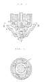
- Fig. 8 shows the overall structure of the transferred plasma arc torch according to the present invention.
- Designated at reference numeral 2 is a cylindrical electrode holder which holds an electrode 3 flxedly at the axial portion of its tip. Moreover, this tip of the electrode holder 2 is enclosed at a gap by a nozzle 1 to form this gap at the inside of the nozzle 1 into a tapered working gas passage 4.
- the inside of the aforementioned electrode holder 2 and the outside of the nozzle 1 are made to communicate with each other through a cooling water passage 5.
- a swirler 6 for swirling the working gases generally tangentially up to the tip of the electrode holder 2.
- the nozzle 1 has its tip formed with a throat 1 a having a diameter d and a length l . Inside of this throat 1 a , there is formed a generally cylindrical chamber 7 which has an internal diameter D and an axial length H and which is positioned to face the electrode 3. The internal diameter D of the space 7 is several times as large as the diameter d of the throat 1 a .
- the working gases flowing into the nozzle 1 are swirled by the swirler 6 so that the swirling flow moves downstream of the nozzle 1.
- the working gases have only the swirling velocity component at first, but their velocity is accelerated the more as the effective area of the passage becomes the smaller, until it takes the maximum at the position facing the electrode 3. After this, the working gases pass through the chamber 7 of the nozzle 1 until they are discharged from the throat 1 a .
- the axial velocity component of the working gases passing through the chamber 7 is maintained at a small level over the distance H of the chamber 7 and is then accelerated to the sonic level at the throat 1 a . Since, in the chamber 7, the swirling velocity component is retained at the high level, there arises no problem in holding the arc stably.
- the working gases are subjected to a velocity difference while they are passing through their passage 4 or the gap between the nozzle 1 and the electrode holder 3, in case the center lines of the two members 1 and 3 are finely offset.
- disturbances are established in the space downstream of the lower end face of the electrode due to the asymmetrical velocity distributions relative to the center line of the nozzle.
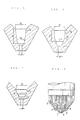
- Figs. 5 to 7 show the individual essential portions of other specific embodiments of the present invention, respectively.
- a chamber 7a has a shape of a frustum of cone, as expressed by D1 > D2.
- the prominent effects can be attained if the following relations are satisfied: 1.5 ⁇ D2/ d ⁇ 10; and 0.75 ⁇ H/ D2 ⁇ 5.
- a chamber 7b has a warhead shape having an outer circumference formed of a smooth curve.
- the prominent effects can be attained If the following relations are satisfied: 1.5 ⁇ D*/ d ⁇ 10; and 0.75 ⁇ H*/ D* ⁇ 5.
- a chamber 7c is formed to have a multiplicity of steps of cylinders having their diameters reduced gradually to the outside.
- the prominent effects can be attained if the following relations are satisfied: 1.5 ⁇ D2/ d ⁇ 10; and 0.75 ⁇ H/ D1 ⁇ 5.
- the bevel angles ⁇ (i.e., the angles of inclination) of the above-specified two examples are plotted in Figs. 9A and 9B. It could be found that the cutting quality of the embodiment of the present invention, as shown in Fig. 9B, is better to have a smaller inclination of cut face than that of the example of the prior art, as shown in Fig. 9A, even after a long use. Moreover, another accompanying phenomenon is that the quantity of the dross to be attached to the lower end of the cut face is drastically reduced.
Landscapes
- Physics & Mathematics (AREA)
- Engineering & Computer Science (AREA)
- Plasma & Fusion (AREA)
- Spectroscopy & Molecular Physics (AREA)
- Mechanical Engineering (AREA)
- Geometry (AREA)
- Arc Welding In General (AREA)
- Plasma Technology (AREA)
Abstract
Applications Claiming Priority (3)
| Application Number | Priority Date | Filing Date | Title |
|---|---|---|---|
| JP63325962A JP2516804B2 (ja) | 1988-12-26 | 1988-12-26 | プラズマト−チ |
| JP325962/88 | 1988-12-26 | ||
| PCT/JP1989/001300 WO1990007395A1 (fr) | 1988-12-26 | 1989-12-25 | Chalumeau a plasma a arc transfere |
Publications (3)
| Publication Number | Publication Date |
|---|---|
| EP0452494A1 true EP0452494A1 (fr) | 1991-10-23 |
| EP0452494A4 EP0452494A4 (en) | 1992-03-11 |
| EP0452494B1 EP0452494B1 (fr) | 1996-05-01 |
Family
ID=18182540
Family Applications (1)
| Application Number | Title | Priority Date | Filing Date |
|---|---|---|---|
| EP90900362A Expired - Lifetime EP0452494B1 (fr) | 1988-12-26 | 1989-12-25 | Chalumeau a plasma a arc transfere |
Country Status (6)
| Country | Link |
|---|---|
| US (1) | US5214263A (fr) |
| EP (1) | EP0452494B1 (fr) |
| JP (1) | JP2516804B2 (fr) |
| KR (1) | KR0136576B1 (fr) |
| DE (1) | DE68926396T2 (fr) |
| WO (1) | WO1990007395A1 (fr) |
Cited By (7)
| Publication number | Priority date | Publication date | Assignee | Title |
|---|---|---|---|---|
| EP0639041A1 (fr) * | 1993-08-11 | 1995-02-15 | Miller Thermal, Inc. | Pistolet de pulvérisation par plasma d'arc et anode correspondante |
| US5569397A (en) * | 1993-07-28 | 1996-10-29 | Kabushiki Kaisha Komatsu Seisakusho | Plasma torch |
| US5591356A (en) * | 1992-11-27 | 1997-01-07 | Kabushiki Kaisha Komatsu Seisakusho | Plasma torch having cylindrical velocity reduction space between electrode end and nozzle orifice |
| DE19626941A1 (de) * | 1996-07-04 | 1998-01-08 | Castolin Sa | Verfahren zum Beschichten oder Schweißen leicht oxidierbarer Werkstoffe sowie Plasmabrenner dafür |
| EP0461263B1 (fr) * | 1990-01-04 | 1998-04-01 | Nkk Corporation | Chalumeau à plasma à arc instable |
| EP0927594A1 (fr) * | 1997-12-23 | 1999-07-07 | Castolin S.A. | Procédé pour déposer des revêtements sur des matériaux |
| WO1999056507A1 (fr) * | 1998-04-27 | 1999-11-04 | Hypertherm, Inc. | Buse pour chalumeau a arc de plasma pourvue d'un orifice de sortie ayant un rayon d'entree et un rapport longueur sur diametre augmente |
Families Citing this family (12)
| Publication number | Priority date | Publication date | Assignee | Title |
|---|---|---|---|---|
| JP2681251B2 (ja) * | 1993-07-14 | 1997-11-26 | 動力炉・核燃料開発事業団 | プラズマジェットトーチ用拘束チップ |
| JPH07314143A (ja) * | 1994-05-25 | 1995-12-05 | Komatsu Ltd | プラズマ切断方法 |
| USD379577S (en) * | 1995-09-06 | 1997-06-03 | The Esab Group, Inc. | Nozzle for a plasma arc torch |
| US6191380B1 (en) * | 1999-06-16 | 2001-02-20 | Hughen Gerrard Thomas | Plasma arc torch head |
| DE10144516B4 (de) * | 2001-09-10 | 2004-03-25 | Kjellberg Finsterwalde Elektroden Und Maschinen Gmbh | Plasmabrenner |
| US20070045241A1 (en) * | 2005-08-29 | 2007-03-01 | Schneider Joseph C | Contact start plasma torch and method of operation |
| FR2943209B1 (fr) * | 2009-03-12 | 2013-03-08 | Saint Gobain Ct Recherches | Torche a plasma avec injecteur lateral |
| US9089319B2 (en) | 2010-07-22 | 2015-07-28 | Plasma Surgical Investments Limited | Volumetrically oscillating plasma flows |
| CN103563491A (zh) * | 2011-03-25 | 2014-02-05 | 伊利诺斯工具制品有限公司 | 具有改进的等离子喷嘴的等离子体喷枪系统 |
| EP2707098A4 (fr) | 2011-05-13 | 2014-05-07 | Thomas J Sheperak | Système, appareil et procédé de soin des blessures par faisceau d'électrons dirigé par plasma |
| DE102018100917A1 (de) * | 2017-09-22 | 2019-03-28 | Kjellberg-Stiftung | Düse für einen Plasmabrennerkopf, Laserschneidkopf und Plasma-Laser-Schneidkopf, Anordnungen, Plasmabrennerkopf und Plasmabrenner mit selbiger/selbigen, Laserschneidkopf mit selbiger/selbigen und Plasma-Laser-Schneidkopf mit selbiger/selbigen |
| CA3191050A1 (fr) | 2020-08-28 | 2022-03-03 | Nikolay Suslov | Systemes, procedes et dispositifs pour generer un flux de plasma etendu principalement radialement |
Family Cites Families (12)
| Publication number | Priority date | Publication date | Assignee | Title |
|---|---|---|---|---|
| US2898441A (en) * | 1957-07-03 | 1959-08-04 | Union Carbide Corp | Arc torch push starting |
| FR1207809A (fr) * | 1957-08-09 | 1960-02-18 | Knapsack Ag | Dispositif d'arc électrique à courant monophasé ou polyphasé pour la production d'un courant de gaz à haute densité d'énergie |
| CH408230A (fr) * | 1964-05-11 | 1966-02-28 | Secheron Atel | Procédé de soudure de tôles minces, au moyen de l'arc électrique |
| US3521023A (en) * | 1968-07-03 | 1970-07-21 | North American Rockwell | Plasma torch |
| SU493097A1 (ru) * | 1974-10-28 | 1978-06-25 | Ордена Ленина И Трудового Красного Знамени Институт Электросварки Имени Е.О.Патона | Плазменный резак |
| DE2900330A1 (de) * | 1978-01-09 | 1979-07-12 | Inst Elektroswarki Patona | Verfahren zur plasmaerzeugung in einem plasma-lichtbogen-generator und vorrichtung zur durchfuehrung des verfahrens |
| JPS5750146Y2 (fr) * | 1979-07-19 | 1982-11-02 | ||
| US4311897A (en) * | 1979-08-28 | 1982-01-19 | Union Carbide Corporation | Plasma arc torch and nozzle assembly |
| JPS5750146A (en) * | 1980-09-09 | 1982-03-24 | Sony Tektronix Corp | Signal selector |
| JPS6228084A (ja) * | 1985-07-30 | 1987-02-06 | Akira Kanekawa | プラズマ・ジエツト・ト−チ |
| US4748312A (en) * | 1986-04-10 | 1988-05-31 | Thermal Dynamics Corporation | Plasma-arc torch with gas cooled blow-out electrode |
| US4954688A (en) * | 1989-11-01 | 1990-09-04 | Esab Welding Products, Inc. | Plasma arc cutting torch having extended lower nozzle member |
-
1988
- 1988-12-26 JP JP63325962A patent/JP2516804B2/ja not_active Expired - Fee Related
-
1989
- 1989-12-25 EP EP90900362A patent/EP0452494B1/fr not_active Expired - Lifetime
- 1989-12-25 KR KR1019900701845A patent/KR0136576B1/ko not_active Expired - Fee Related
- 1989-12-25 WO PCT/JP1989/001300 patent/WO1990007395A1/fr not_active Ceased
- 1989-12-25 DE DE68926396T patent/DE68926396T2/de not_active Expired - Fee Related
- 1989-12-25 US US07/689,279 patent/US5214263A/en not_active Expired - Lifetime
Cited By (8)
| Publication number | Priority date | Publication date | Assignee | Title |
|---|---|---|---|---|
| EP0461263B1 (fr) * | 1990-01-04 | 1998-04-01 | Nkk Corporation | Chalumeau à plasma à arc instable |
| US5591356A (en) * | 1992-11-27 | 1997-01-07 | Kabushiki Kaisha Komatsu Seisakusho | Plasma torch having cylindrical velocity reduction space between electrode end and nozzle orifice |
| US5569397A (en) * | 1993-07-28 | 1996-10-29 | Kabushiki Kaisha Komatsu Seisakusho | Plasma torch |
| EP0639041A1 (fr) * | 1993-08-11 | 1995-02-15 | Miller Thermal, Inc. | Pistolet de pulvérisation par plasma d'arc et anode correspondante |
| DE19626941A1 (de) * | 1996-07-04 | 1998-01-08 | Castolin Sa | Verfahren zum Beschichten oder Schweißen leicht oxidierbarer Werkstoffe sowie Plasmabrenner dafür |
| WO1998001256A1 (fr) * | 1996-07-04 | 1998-01-15 | Castolin S.A. | Procede pour enduire ou souder des materiaux facilement oxydables et chalumeau au plasma pour mettre en oeuvre ce procede |
| EP0927594A1 (fr) * | 1997-12-23 | 1999-07-07 | Castolin S.A. | Procédé pour déposer des revêtements sur des matériaux |
| WO1999056507A1 (fr) * | 1998-04-27 | 1999-11-04 | Hypertherm, Inc. | Buse pour chalumeau a arc de plasma pourvue d'un orifice de sortie ayant un rayon d'entree et un rapport longueur sur diametre augmente |
Also Published As
| Publication number | Publication date |
|---|---|
| EP0452494A4 (en) | 1992-03-11 |
| US5214263A (en) | 1993-05-25 |
| DE68926396T2 (de) | 1996-11-28 |
| DE68926396D1 (de) | 1996-06-05 |
| WO1990007395A1 (fr) | 1990-07-12 |
| KR910700119A (ko) | 1991-03-13 |
| JPH02175080A (ja) | 1990-07-06 |
| JP2516804B2 (ja) | 1996-07-24 |
| KR0136576B1 (ko) | 1998-07-01 |
| EP0452494B1 (fr) | 1996-05-01 |
Similar Documents
| Publication | Publication Date | Title |
|---|---|---|
| EP0452494B1 (fr) | Chalumeau a plasma a arc transfere | |
| KR100199782B1 (ko) | 물분사 노즐 조립체를 가진 플라즈마 아크토치 | |
| US5786561A (en) | Nozzle assembly for laser beam cutting | |
| KR100357782B1 (ko) | 응집성가스분사방법및장치 | |
| EP0152891B1 (fr) | Buse d'injection | |
| US4646977A (en) | Spray nozzle | |
| EP0640401A1 (fr) | Buse pour pulvérisation pneumatique avec des orifices de décharge inclinés | |
| US5803948A (en) | Process and device for introducing gases into metal melts | |
| JPH01111464A (ja) | スケール除去用ノズル | |
| WO1994012308A1 (fr) | Chalumeau a plasma | |
| US5700421A (en) | Cutting nozzle assembly for a postmixed oxy-fuel gas torch | |
| US4913405A (en) | Laser cutting nozzle, cutting head comprising said nozzle and laser cutting method using said elements | |
| US20110210109A1 (en) | Laser Processing Nozzles and Methods | |
| EP0711622B1 (fr) | Chalumeau a plasma | |
| US20190283213A1 (en) | Multi-jet abrasive head | |
| JP2009101411A (ja) | デスケーリングノズル | |
| US2408588A (en) | Apparatus for dividing or desurfacing metal by use of oxidizing sets | |
| US6773484B2 (en) | Extensionless coherent jet system with aligned flame envelope ports | |
| US5736708A (en) | Plasma torch head with nozzle providing an improved cut and plasma torch including the same | |
| US6709630B2 (en) | Metallurgical lance and apparatus | |
| US5202544A (en) | Method of machining plate materials with a plasma cutter and plasma torch | |
| US4664621A (en) | Gas cutting torch | |
| US2365411A (en) | Deseaming apparatus | |
| JPH07185823A (ja) | プラズマトーチ | |
| TWI778514B (zh) | 聚焦管及其用途 |
Legal Events
| Date | Code | Title | Description |
|---|---|---|---|
| PUAI | Public reference made under article 153(3) epc to a published international application that has entered the european phase |
Free format text: ORIGINAL CODE: 0009012 |
|
| 17P | Request for examination filed |
Effective date: 19910606 |
|
| AK | Designated contracting states |
Kind code of ref document: A1 Designated state(s): DE FR GB |
|
| A4 | Supplementary search report drawn up and despatched |
Effective date: 19920123 |
|
| AK | Designated contracting states |
Kind code of ref document: A4 Designated state(s): DE FR GB |
|
| 17Q | First examination report despatched |
Effective date: 19940517 |
|
| GRAH | Despatch of communication of intention to grant a patent |
Free format text: ORIGINAL CODE: EPIDOS IGRA |
|
| GRAA | (expected) grant |
Free format text: ORIGINAL CODE: 0009210 |
|
| AK | Designated contracting states |
Kind code of ref document: B1 Designated state(s): DE FR GB |
|
| REF | Corresponds to: |
Ref document number: 68926396 Country of ref document: DE Date of ref document: 19960605 |
|
| ET | Fr: translation filed | ||
| PLBE | No opposition filed within time limit |
Free format text: ORIGINAL CODE: 0009261 |
|
| STAA | Information on the status of an ep patent application or granted ep patent |
Free format text: STATUS: NO OPPOSITION FILED WITHIN TIME LIMIT |
|
| 26N | No opposition filed | ||
| PGFP | Annual fee paid to national office [announced via postgrant information from national office to epo] |
Ref country code: GB Payment date: 19971216 Year of fee payment: 9 |
|
| PGFP | Annual fee paid to national office [announced via postgrant information from national office to epo] |
Ref country code: FR Payment date: 19981209 Year of fee payment: 10 |
|
| PG25 | Lapsed in a contracting state [announced via postgrant information from national office to epo] |
Ref country code: GB Free format text: LAPSE BECAUSE OF NON-PAYMENT OF DUE FEES Effective date: 19981225 |
|
| GBPC | Gb: european patent ceased through non-payment of renewal fee |
Effective date: 19981225 |
|
| PG25 | Lapsed in a contracting state [announced via postgrant information from national office to epo] |
Ref country code: FR Free format text: LAPSE BECAUSE OF NON-PAYMENT OF DUE FEES Effective date: 20000831 |
|
| REG | Reference to a national code |
Ref country code: FR Ref legal event code: ST |
|
| PGFP | Annual fee paid to national office [announced via postgrant information from national office to epo] |
Ref country code: DE Payment date: 20021231 Year of fee payment: 14 |
|
| PG25 | Lapsed in a contracting state [announced via postgrant information from national office to epo] |
Ref country code: DE Free format text: LAPSE BECAUSE OF NON-PAYMENT OF DUE FEES Effective date: 20040701 |