EP0452519A1 - Vorrichtung zum Festhalten eines Fahrzeuges an einer Rampe - Google Patents
Vorrichtung zum Festhalten eines Fahrzeuges an einer Rampe Download PDFInfo
- Publication number
- EP0452519A1 EP0452519A1 EP90107193A EP90107193A EP0452519A1 EP 0452519 A1 EP0452519 A1 EP 0452519A1 EP 90107193 A EP90107193 A EP 90107193A EP 90107193 A EP90107193 A EP 90107193A EP 0452519 A1 EP0452519 A1 EP 0452519A1
- Authority
- EP
- European Patent Office
- Prior art keywords
- hook
- arm
- housing
- ramp
- cover plate
- Prior art date
- Legal status (The legal status is an assumption and is not a legal conclusion. Google has not performed a legal analysis and makes no representation as to the accuracy of the status listed.)
- Granted
Links
- 229910000831 Steel Inorganic materials 0.000 claims description 4
- 239000010959 steel Substances 0.000 claims description 4
- 230000003287 optical effect Effects 0.000 claims description 2
- 230000000903 blocking effect Effects 0.000 abstract 1
- 238000000034 method Methods 0.000 description 8
- 238000010276 construction Methods 0.000 description 2
- 238000003032 molecular docking Methods 0.000 description 2
- 230000000694 effects Effects 0.000 description 1
- 239000000463 material Substances 0.000 description 1
- 238000005096 rolling process Methods 0.000 description 1
Images


Classifications
-
- B—PERFORMING OPERATIONS; TRANSPORTING
- B65—CONVEYING; PACKING; STORING; HANDLING THIN OR FILAMENTARY MATERIAL
- B65G—TRANSPORT OR STORAGE DEVICES, e.g. CONVEYORS FOR LOADING OR TIPPING, SHOP CONVEYOR SYSTEMS OR PNEUMATIC TUBE CONVEYORS
- B65G69/00—Auxiliary measures taken, or devices used, in connection with loading or unloading
- B65G69/003—Restraining movement of a vehicle at a loading station using means not being part of the vehicle
Definitions
- the invention relates to a device for holding a vehicle to a loading ramp, which takes effect after docking and thus prevents unintentional rolling away or early departure of the vehicle during the loading process, and releases the vehicle again after the loading process has ended.
- the aim of the present invention is therefore to provide a device for holding a vehicle on a ramp, which is suitable for as many vehicle types as possible and also for ramps with self-supporting dock levellers which have cutouts for inserting vehicle tail lifts.
- the device should also be easy to install, require no special structural measures and make the "interface ramp" safe.
- a device comprising a low housing (3), a rotatable hook (4) therein, a drive and a locking device therefor, which are constructed in such a way that vehicles with tail lifts can also be easily locked.
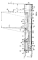
- FIG. 1 shows a ramp (1) in which a dock leveler can be installed.
- the space (38) under the dock leveler (39) is open.
- the tail lifts that may be attached to the vehicles are pushed into this room.
- a housing (3) which is preferably rectangular or trapezoidal and made, for example, of steel or plastic, is anchored in the floor (2) with fastenings (24) on the ramp floor (2).
- the hook (4) holds an underride guard (37), which is located in area (a) at height (h) from the floor of the ramp in front of the ramp.
- the underrun protection can be no less than the distance (b) from the ramp, since the distance (b) depends on the thickness of the crash bumpers (40) and the minimum width of the underride guard (37) are calculated and the length of the rear cover plate (15) corresponds to the device according to the invention.
- the housing (3) is of low construction, since its height (y) is decisive for whether tail lifts can still be pushed over the housing (3) of the holding structure into the existing tail gate opening (38).
- the maximum height (y) is preferably about 200 mm.
- a bevel (41) can be attached in front of the housing (3) to protect it, which prevents damage when docking with the tail lifts lowered.
- the system can also be equipped with an optical lighting system, such as a red-green traffic light outside the cargo area and a red-orange-green traffic light inside the cargo area.
- an optical lighting system such as a red-green traffic light outside the cargo area and a red-orange-green traffic light inside the cargo area.
- the hook drive and the traffic lights are controlled from a control box. Operation is carried out by operating switches and buttons.
- the switches can preferably be limit switches or proximity switches.
- the entire loading process then proceeds as follows:
- the hook (4) is in the horizontal rest position in the housing (3), the traffic light in the hall is red so that it cannot be loaded.
- the traffic light outside shows green, the arriving vehicle can drive backwards onto the ramp (1).
- the ramp staff actuates the hook (4) using appropriate electrical means, the traffic light on the outside switching to red, while the traffic light in the cargo area also lights up red.
- the hook (4) now turns to the vertical position and is automatically pushed towards the ramp against the underrun protection (37). As soon as this is reached, the vehicle is locked. It can no longer roll away or drive away.
- the traffic light inside now shows green, the charging process can begin, the traffic light outside remains red.
- the hook (4) is automatically unlocked again by the ramp personnel by actuating the appropriate electrical means.
- the traffic light jumps to red on the inside, and remains red on the outside until the hook (4) is in the horizontal rest position again. Then the traffic light on the outside changes to green again, the vehicle can now leave the ramp (1) again.
- the traffic light is red inside and green outside.
- the vehicle can drive up to the ramp (1).
- the ramp staff actuates the hook (4) that is still in retirement at the push of a button, the traffic light on the outside jumps to red, and the inside it stays on red.
- the hook (4) reaches the vertical position and then moves the entire area (a) towards the ramp in this position.
- the traffic light in the hall switches to an orange flashing light.
- the ramp personnel know that the vehicle is now not secured.
- a bypass is consciously operated manually, which moves the hook (4) back into the rest position. If the hook (4) is now in the rest position, the traffic light on the inside switches to orange continuous light and the traffic light remains red. Now an "unsecured charging process" can take place.
- the starting position of the traffic lights red inside and green outside
- the vehicle can then leave the ramp again.
- control box for control preferably has three basic operating switches, namely “locking”, unlocking ”and“ bypass for unsecured charging. ”All further switching and movements then take place automatically.
- the dock leveler (39) can only be used when the hook (4) holds the vehicle and can only be released when the dock leveler (39) is in the rest position again.
- FIGS. 2-4 The mechanism of the holding device according to the invention is shown in FIGS. 2-4 and is explained below:
- the hook (4) of the device according to the invention is in the starting or rest position horizontally in the housing (3) and adjoins the front cover plate (13) of the housing (3).
- the vehicle drives backwards on ramp (1).
- the underrun protection (37), or other fastening means, of the vehicle is located at height (h) in area (a) in front of the ramp (1).
- the hook (4) is mounted with the axis (5) between the upper hook guide (20) and the lower hook guide (21).
- the axis (5) is also rotatably supported in a tube (6) on which a rack (7) with a locking device is fastened in the direction of the front cover plate (13).
- the tube (6) is connected to a pull cable (8) which runs over deflection rollers (17) to the edge of the housing and then in the direction of the front cover plate (13) via a tensioning element (18) and is fixed in the abutment (19) of the housing (3).
- the tensioning element (18) is preferably a spring with a linear force distribution.
- the locking device of the rack (7) consists of three parts.
- Part 1 consists of an arm (33) and an approximately vertically arranged bolt (35), both of which are firmly connected and can rotate about the axis (32).
- Part 2 is an arm (31) which is vertically connected on the one hand to the arm (33) via axis (43), this connection having a margin. This margin is preferably an elongated hole.
- the arm (31) is connected via axis (42) to the rotatable arm (28), preferably via a round hole.
- Arm (28) is part of the third part of the locking device.
- This third part represents the operating arm of the entire mechanism and consists of an arm (28) which can be rotated about the axis (27) and which is connected at its lower end to the abutment (30) of the housing (3) via a spring element (29) .
- Part 1 bolt (35)
- Part 2 arm (31)
- the locking element can preferably have a spring element (34) to support the bolt (35), the spring force of which, however, must be so small that it does not influence the action of the operating arm (28) with the spring element (29).
- the device according to the invention also has a drive device (16) for the hook (4) located under the hook (4), which is connected to the corresponding fastening (9).
- the fastening (9) is in turn connected to the front support plate (11) via the guide rod (10) and furthermore has a lower and an upper guide (25, 26). In the rest position there is a second support plate (12) on the guide (23) above the support plate (11). Support plates (11) and (12) continue to have a lower support plate guide (22).
- the guide rod (10) also has a driver, not shown here, for the support plate (12).
- the drive or cylinder (16) is now activated for pushing out via known electrical / electronic means and pushes the attachment (9) onto the arm (28) (cf. FIG. 3).
- the front support plate (11) is pulled away from the ramp (1) via the guide rod (10).
- the driver (not shown) also pulls the support plate (12) as soon as the support plate (11) is on the guide (23).
- Support plate (11) presses against the hook (4).
- the resulting torque turns the hook (4) into the vertical position.
- the front cover plate (13) supports the upward movement of the hook (4), since the underside of the hook (4) slides over the cover plate (13).
- the support plate (11) thus pushes the hook (4) forward and at the same time slowly rotates it vertically.
- the pull cable (8) tensions the tensioning element (18) slowly and pulls it in the direction of the ramp (1). Finally, the axis (5) of the hook (4) abuts the abutment (36) and the support plate (11) turns the hook (4) in the vertical position.
- the drive or cylinder (16) reaches its maximum position.
- the attachment (9) then presses the operating arm (28) towards the front cover plate (14), the tension element (29) tensions, arm (31) pulls arm (33), possibly supported by a spring (34), also in the direction the front cover plate (14) and the bolt (35) then engage in the rack (7) (see FIG. 4).
- the tensioning element (18) now pulls the hook (4) in the (x) direction via the pull cable (8) until the hook (4) underrun protection of the vehicle hits, max. So over the area (a).
- the hook (4) is now in the holding position. If the vehicle tries to drive away, the underride guard presses against the hook (4) at height (h). Since the support plates (11) and (12) fill the entire guide area between positions (21) and (22), the hook (4) can no longer be turned back into the horizontal position in the entire work area (a).
- the bolt (35) prevents the rack (7) from being moved away from the ramp (1). The vehicle is therefore safely held in front of the ramp (1), and loading can now take place.
- arm (31) In order to ensure trouble-free functioning even when the vehicle presses the hook (4) away from the ramp (1), arm (31) has a clearance, preferably an elongated hole, at point (43). If the rack (7) presses against the bolt (35) with great force, the arm (33) tends to turn in the direction of the ramp (1). If there were a connection (43) without clearance, the voltages would also be transmitted to the drive (16) via arm (31) and (28).
- Unlocking after the positioning process is completed is as follows:
- the drive or cylinder (16) retracts in the direction of the ramp (1), the fastening (9) releases the arm (28) again, the spring element (29) pulls the arm (28) and, via the arm (31), also the arm (33) in the direction of the ramp (1), the latch (35) lifts out of the rack (7).
- the fastening (9) pushes the support plate (11) over the guide (23) in the direction of the ramp (1) via the guide rod (10).
- the support plate (11) first pushes the support plate (12) towards the ramp (1) until it comes to rest on the guide (23) in the rest position and then pushes over the support plate (12) also in the rest position.
- the device according to the invention can also be installed lowered into the floor (2) in front of the ramp (1) and instead of the underrun protection (37) e.g. block the wheels of the vehicle.
- This is possible by adapting the drive (16), which can then preferably be a chain drive or the like.
- the hook (4) can be made of a mechanically resistant material such as Plastic or a steel beam.
- the advantage of the device according to the invention lies in the fact that vehicles with tail lifts can also be locked, and optimum safety through special designs with regard to the chronological sequence of the charging process. Furthermore, no complicated, expensive construction measures are required for this.
- the device can be used to hold onto underrun protection or similar fastening means on vehicles or can also be used to lock wheels if no other fastening means are available.
Landscapes
- Engineering & Computer Science (AREA)
- Mechanical Engineering (AREA)
- Auxiliary Methods And Devices For Loading And Unloading (AREA)
- Motorcycle And Bicycle Frame (AREA)
- Steering Control In Accordance With Driving Conditions (AREA)
- Control Of The Air-Fuel Ratio Of Carburetors (AREA)
- Non-Silver Salt Photosensitive Materials And Non-Silver Salt Photography (AREA)
- Lock And Its Accessories (AREA)
Abstract
Description
- Gegenstand der Erfindung ist eine Vorrichtung zum Festhalten eines Fahrzeuges an einer Laderampe, welche nach dem Andocken wirksam wird und so unbeabsichtigtes Wegrollen oder zu frühes Wegfahren des Fahrzeuges während des Verladevorganges verhindert, sowie nach Beendigung des Verladevorganges das Fahrzeug wieder freigibt.
- Die meisten Fahrzeuge, die im europäischen Raum zu Transportzwecken be- und entladen werden, weisen einen Unterfahrschutz auf, der in Europa aufgrund entsprechender Richtlinien bestimmten Erfordernissen genügen muß:
- a) er darf einen maximalen Abstand, von der Rückseite des Aufbaus gemessen, nicht überschreiten,
- b) er darf eine maximale Höhe vom Boden aus gemessen nicht überschreiten,
- c) er muß einer bestimmten Zug- bzw. Druckkraft widerstehen.
- Diese Erfordernisse sind auch bei der Konstruktion von Haltevorrichtungen zu beachten, welche an dem Unterfahrschutz befestigt werden sollen. Hinzu kommt, daß solche Haltesysteme auch vom eventuellen Vorhandensein von Ladebordwänden der vorgenannten Fahrzeuge beeinflußt werden.
- Gerade in dieser Hinsicht haben bisher bekannte Systeme, wie z.B. das in der EP-B 0 012 386 beschriebene, den Nachteil, daß sie für Fahrzeuge mit Ladebordwänden nicht geeignet sind. Denn sie weisen entweder eine so große Bauhöhe auf, daß die für die Unterfahrbarkeit gemachte Aussparung zu klein ist, oder die Systeme sind unter einer Ladebrücke an der Rampenvorderseite befestigt und sind somit ein Hindernis für die Ladebordwände, die in die Aussparung geschoben werden sollen. Ausführungen wie im obengenannten Patent sind daher für Europa meistens ungeeignet, da durch die hohe Anzahl von Fahrzeugen mit Ladebordwänden die meisten Überladebrücken freitragend ausgeführt sind, also keine Betonrampe für eine Befestigung zur Verfügung steht.
- Amerikanische Systeme weisen den Nachteil auf, daß ihr Verstellbereich nur sehr gering ist. In Europa darf der Unterfahrschutz maximal 450 mm vom hinteren Ende des Fahrzeugs entfernt sein, so daß sich die Verstellbarkeit der Haltevorrichtungen ebenfalls in dieser Größenordnung bewegen muß. Bestehende amerikanische Lösungen decken jedoch meist nur die Hälfte dieses Bereichs ab.
- Ziel vorliegender Erfindung ist daher die Bereitstellung einer Vorrichtung zum Festhalten eines Fahrzeugs an einer Rampe, die für möglichst viele Fahrzeugtypen und auch für Rampen mit freitragenden Überladebrücken, die Aussparungen zum Einschieben von Fahrzeugladebordwänden aufweisen, geeignet ist. Die Vorrichtung soll ferner leicht montierbar sein, keine besonderen baulichen Maßnahmen erfordern und die "Schnittstelle Rampe" sicher machen.
- Diese Aufgabe wird erfindungsgemäß gelöst durch eine Vorrichtung, umfassend ein niedriges Gehäuse (3), einen darin befindlichen drehbaren Haken (4), eine Antriebs- sowie eine Verriegelungsvorrichtung hierfür, die so konstruiert sind, daß auch Fahrzeuge mit Ladebordwänden leicht arretiert werden können.
- Die Erfindung und besondere Ausgestaltungen derselben werden anhand der nachfolgenden Abbildungen näher erläutert.
- Dabei zeigt
- Figur 1 eine Vorderansicht und einen Längsschnitt entlang der Linie A-A des Systems vor einer Rampe mit Überladebrücke,
- Figur 2 einen Längsschnitt durch das System in Ruhestellung,
- Figur 3 einen Längsschnitt durch das System, wenn das Fahrzeug vor der Rampe steht und das Haltesystem in Wirkstellung gebracht wird, und
- Figur 4 einen Längsschnitt durch das System, wenn es sich in Wirkstellung befindet.
- Figur 1 zeigt eine Rampe (1), in der eine Überladebrücke eingebaut sein kann. Bei freitragenden Überladebrücken ist der Raum (38) unter der Überladebrücke (39) offen. In diesen Raum werden die an den Fahrzeugen eventuell angebrachten Ladebordwände geschoben. Vor der Rampe (1) ist auf dem Rampenboden (2) ein Gehäuse (3), welches vorzugsweise rechteckig oder trapezförmig und beispielsweise aus Stahl oder Kunststoff ist, mit Befestigungen (24) im Boden (2) verankert. Der Haken (4) hält einen Unterfahrschutz (37) fest, der sich im Bereich (a) auf Höhe (h) vom Rampenboden aus vor der Rampe befindet. Der Unterfahrschutz kann dabei nicht weniger als Abstand (b) von der Rampe entfernt sein, da sich der Abstand (b) aus der Dicke der Anprallpuffer (40) und der minimalen Breite des Unterfahrschutzes (37) errechnet und der Länge der hinteren Abdeckplatte (15) der erfindungsgemäßen Vorrichtung entspricht. Das Gehäuse (3) ist niedrig gebaut, da seine Höhe (y) maßgebend dafür ist, ob Ladebordwände noch über das Gehäuse (3) der Haltekonstruktion hinweg in die eventuell vorhandene Ladebordwandöffnung (38) eingeschoben werden können. Die maximale Höhe (y) beträgt vorzugsweise etwa 200 mm. Vor dem Gehäuse (3) kann gewünschtenfalls zum Schutz desselben eine Schräge (41) angebracht sein, die Beschädigungen beim Andocken mit abgesenkten Ladebordwänden verhindert.
- Um optimale Sicherheit zu gewährleisten, kann das System zusätzlich mit einer optischen Lichtanlage, wie beispielsweise einer rot-grünen Ampel außerhalb des Laderaums und einer rot-orange-grünen Ampel innerhalb des Laderaums, ausgestattet sein.
- Die Steuerung des Hakenantriebes sowie der Ampeln erfolgt von einem Steuerkasten aus. Bedienung erfolgt durch das Betätigen von Schaltern und Tastern. Die Schalter können vorzugsweise Endschalter bzw. Näherungsschalter sein.
- Der gesamte Ladevorgang verläuft dann wie folgt:
Haken (4) befindet sich in waagrechter Ruhestellung im Gehäuse (3), die Ampel in der Halle ist rot, so daß nicht geladen werden kann. Die Ampel außen zeigt grün an, das ankommende Fahrzeug kann rückwärts an die Rampe (1) heranfahren. Das Rampenpersonal betätigt den Haken (4) über entsprechende elektrische Mittel,wobei die Ampel außen auf rot schaltet, während die Ampel im Laderaum ebenfalls rot aufleuchtet. Haken (4) dreht nun in vertikale Stellung und wird automatisch in Richtung Rampe gegen den Unterfahrschutz (37) geschoben. Sobald dieser erreicht ist, ist das Fahrzeug verriegelt. Es kann nicht mehr wegrollen oder wegfahren. Die Ampel innen zeigt jetzt grün, der Ladevorgang kann beginnen, die Ampel außen bleibt rot. - Nach Beendigung des Verladevorgangs wird der Haken (4), durch Betätigung entsprechender elektrischer Mittel durch das Rampenpersonal wieder automatisch entriegelt. Gleichzeitig springt innen die Ampel wieder auf rot, außen bleibt sie solange rot, bis sich der Haken (4) wieder in horizontaler Ruhestellung befindet. Dann springt die Ampel außen wieder auf grün, das Fahrzeug kann die Rampe (1) nun wieder verlassen.
- Bei Fahrzeugen, welche keinen geeigneten Unterfahrschutz aufweisen, entsteht folgende Situation:
Die Ampel innen ist rot und außen grün. Das Fahrzeug kann an die Rampe (1) heranfahren. Das Rampenpersonal betätigt wieder mittels Knopfdruck den noch im Ruhestand befindlichen Haken (4), die Ampel außen springt auf rot, innen bleibt sie auf rot. Der Haken (4) erreicht die vertikale Stellung und fährt dann in dieser Stellung den gesamten Bereich (a) Richtung Rampe. Hat er seine Endstellung erreicht, schaltet die Ampel in der Halle auf oranges Blinklicht. Das Rampenpersonal weiß, daß nun keine Sicherung des Fahrzeuges vorliegt. Dann wird bewußt manuell ein Bypass betätigt, der den Haken (4) wieder in Ruhestellung fährt. Befindet sich Haken (4) nun in Ruhestellung, schaltet die Ampel innen auf oranges Dauerlicht und die Außenampel bleibt rot. Nun kann ein "ungesicherter Ladevorgang" stattinden.
Ist dieser beendet, wird die Ausgangstellung der Ampeln (innen rot und außen grün) durch Betätigung des elektrischen Mittels durch das Rampenpersonal wieder eingestellt. Das Fahrzeug kann sodann die Rampe wieder verlassen. - Wie hieraus ersichtlich ist, weist der Schaltkasten zur Steuerung vorzugsweise drei grundlegende Bedienungsschalter auf, und zwar "Verriegelung", Entriegelung" und "Bypass für ungesichertes Laden". Alle weiteren Schaltungen und Bewegungen laufen dann automatisch ab.
- Es ist natürlich auch möglich, andere Schaltungen in Kombination anzuwenden. So kann beispielsweise die Überladebrücke (39) erst dann eingesetzt werden, wenn Haken (4) das Fahrzeug festhält und dieser erst dann wieder gelöst werden kann, wenn sich die Überladebrücke (39) wieder in Ruhestellung befindet.
- Der Mechanismus der erfindungsgemäßen Haltevorrichtung ist in den Figuren 2-4 dargestellt und wird nachfolgend erläutert:
Wie in Figur 2 dargestellt, befindet sich der Haken (4) der erfindungsgemäßen Vorrichtung in der Ausgangs- oder Ruhestellung horizontal im Gehäuse (3) und grenzt dabei an die vordere Abdeckplatte (13) des Gehäuses (3) an. Das Fahrzeug fährt rückwärts an Rampe (1) heran. Der Unterfahrschutz (37), oder sonstige Befestigungsmittel, des Fahrzeugs befindet sich auf Höhe (h) im Bereich (a) vor Rampe (1). - Der Haken (4) ist mit der Achse (5) zwischen der oberen Hakenführung (20) und der unteren Hakenführung (21) gelagert. Die Achse (5) lagert weiterhin drehbar in einem Rohr (6), an dem in Richtung vordere Deckplatte (13) eine Zahnstange (7) mit einer Verriegelungsvorrichtung befestigt ist.
In Richtung hintere Deckplatte (15) ist das Rohr (6) mit einem Zugkabel (8) verbunden, das über Umlenkrollen (17) bis zum Gehäuserand und anschließend in Richtung vordere Deckplatte (13) über ein Spannelement (18) verläuft und in Widerlager (19) des Gehäuses (3) befestigt ist. Das Spannelement (18) ist vorzugsweise eine Feder mit linearer Kraftverteilung. - Die Verriegelungsvorrichtung der Zahnstange (7) besteht aus drei Teilen. Teil 1 besteht aus einem Arm (33) und einem hierzu etwa vertikal angeordneten Riegel (35), die beide fest verbunden sind und um die Achse (32) drehen können. Teil 2 ist ein Arm (31), der vertikal einerseits mit dem Arm (33) über Achse (43) verbunden ist, wobei diese Verbindung einen Spielraum aufweist. Vorzugsweise ist dieser Spielraum ein Langloch. Andererseits ist der Arm (31) über Achse (42) mit dem drehbaren Arm (28), vorzugsweise über ein Rundloch, verbunden. Arm (28) ist ein Teil des dritten Teils der Verriegelungsvorrichtung. Dieser dritte Teil stellt den Bedienungsarm des gesamten Mechanismus dar und besteht aus einem um die Achse (27) drehbaren Arm (28), der an seinem unteren Ende über ein Federelement (29) mit dem Widerlager (30) des Gehäuses (3) verbunden ist. Teil 1 (Riegel (35)) ist über die Achse (43) mit Teil 2 (Arm (31)) und dieser wiederum über Achse (42) mit Teil 3 (Bedienungsarm) verbunden. Das Riegelelement kann vorzugsweise zur Unterstützung des Riegels (35) ein Federelement (34) aufweisen, dessen Federkraft jedoch so klein sein muß, daß es die Wirkung des Bedienungsarms (28) mit Federelement (29) nicht beeinflußt.
- Die erfindungsgemäße Vorrichtung weist weiterhin eine unter dem Haken (4) befindliche Antriebsvorrichtung (16) für den Haken (4) auf, die mit der entsprechenden Befestigung (9) verbunden ist. Die Befestigung (9) ist ihrerseits über die Führungsstange (10) mit der vorderen Stützplatte (11) verbunden und weist weiterhin eine untere und eine obere Führung (25,26) auf. In Ruhestellung befindet sich über der Stützplatte (11) eine zweite Stützplatte (12) auf der Führung (23). Stützplatten (11) und (12) weisen weiterhin eine untere Stützplattenführung (22) auf.
- Die Führungsstange (10) besitzt ferner einen hier nicht dargestellten Mitnehmer für die Stützplatte (12).
- In Ruhestellung, wenn sich also der Haken (4) horizontal im Gehäuse (3) befindet, liegen die Stützplatten (11) und (12) übereinander auf der Ruhestandsführung (23). Antrieb (16) befindet sich dann in Nullstellung. Vorzugsweise wird hierbei ein elektro-hydraulisch, elektrisch oder ein pneumatisch betätigter Zylinder gewählt, der bei Ruhestellung des Hakens (4) ganz eingefahren ist. Das Spannelement (18) ist zu diesem Zeitpunkt entspannt. Das Spannelement (29) zieht den Arm (28) in Richtung Widerlager (30), so daß der Arm (31) den Arm (33) in Richtung Rampe (1) bewegt und so den Riegel (35) aus dem Bereich der Zahnstange (7) heraushebt, d.h. die Verriegelung ist offen.
- Der Antrieb bzw. Zylinder (16) wird nun zum Ausschieben über bekannte elektrische/elektronische Mittel aktiviert und schiebt die Befestigung (9) auf den Arm (28) (vgl. Figur 3). Die vordere Stützplatte (11) wird über die Führungsstange (10) mit von der Rampe (1) weggezogen. Der nicht dargestellte Mitnehmer zieht, sobald sich die Stützplatte (11) auf Führung (23) befindet, auch die Stützplatte (12) mit. Stützplatte (11) drückt gegen den Haken (4). Das dabei entstehende Drehmoment dreht den Haken (4) in die vertikale Position. Die vordere Abdeckplatte (13) unterstützt dabei die Aufwärtsbewegung des Hakens (4), da die Unterseite des Hakens (4) über die Deckplatte (13) gleitet. Die Stützplatte (11) schiebt somit den Haken (4) nach vorne und dreht ihn gleichzeitig langsam vertikal. Dabei spannt das Zugkabel (8) das Spannelement (18) langsam und zieht es in Richtung Rampe (1).
Schließlich stößt die Achse (5) des Hakens (4) gegen das Widerlager (36), und die Stützplatte (11) dreht den Haken (4) in die vertikale Position. Der Antrieb bzw. Zylinder (16) erreicht seine maximale Stellung. Die Befestigung (9) drückt sodann den Bedienungsarm (28) in Richtung vordere Deckplatte (14), das Zugelement (29) spannt sich, Arm (31) zieht Arm (33), eventuell unterstützt durch eine Feder (34), ebenfalls in Richtung vordere Deckplatte (14) und der Riegel (35) greift dann in die Zahnstange (7) (vgl. Figur 4). - Da der Haken (4) in vertikaler Position ist, zieht das Spannelement (18) jetzt über das Zugkabel (8) den Haken (4) in (x)-Richtung, und zwar so lange, bis Haken (4) den Unterfahrschutz des Fahrzeugs trifft, max. also über den Bereich (a).
Der Haken (4) ist jetzt in Halteposition.
Versucht das Fahrzeug wegzufahren, drückt der Unterfahrschutz auf Höhe (h) gegen den Haken (4). Da die Stützplatten (11) und (12) den gesamten Führungsbereich zwischen den Positionen (21) und (22) ausfüllen, kann der Haken (4) im gesamten Arbeitsbereich (a) nicht mehr in die horizontale Stellung zurückgedreht werden. Zusätzlich verhindert der Riegel (35), daß die Zahnstange (7) von der Rampe (1) wegbewegt wird. Das Fahrzeug wird also sicher vor der Rampe (1) gehalten, der Ladebetrieb kann jetzt stattfinden. - Ist der Ladebetrieb beendet, muß der Haken (4) wieder in Ruhestellung gefahren werden.
- Um auch dann, wenn das Fahrzeug den Haken (4) von der Rampe (1) wegdrückt, ein störungsfreies Funktionieren zu gewährleisten, weist Arm (31) im Punkt (43) einen Spielraum, vorzugsweise ein Langloch, auf. Drückt Zahnstange (7) mit großer Kraft gegen Riegel (35), so neigt Arm (33) dazu, Richtung Rampe (1) zu drehen. Wäre hier eine Verbindung (43) ohne Spielraum vorhanden, würden die Spannungen über Arm (31) und (28) auch auf den Antrieb (16) übertragen.
- Dabei könnte das gesamte System verklemmen und nicht mehr ohne Kraftaufwand von außen gelöst werden.
- Die Entriegelung nach beendetem Lagevorgang wird wie folgt vorgenommen:
Der Antrieb bzw. Zylinder (16) fährt Richtung Rampe (1) wieder ein, die Befestigung (9) gibt Arm (28) wieder frei, Federelement (29) zieht Arm (28) und über Arm (31) auch Arm (33) in Richtung Rampe (1), Riegel (35) hebt sich aus der Zahnstange (7). Die Befestigung (9) schiebt über Führungsstange (10) die Stützplatte (11) über Führung (23) in Richtung Rampe (1). Die Stützplatte (11) schiebt erst Stützplatte (12) Richtung Rampe (1), bis diese wieder in Ruhestellung auf Führung (23) zu liegen kommt und schiebt sich dann über Stützplatte (12) auch in Ruhestellung. Diese ist erreicht, wenn der Antrieb (16) ganz zurückgenommen ist bzw. im Falle eines Zylinders ganz eingefahren ist. Dadurch, daß Haken (4) nicht mehr unterstützt ist, fällt er selbst durch Eigengewicht um Achse (5) drehend in die horizontale Stellung. Das Spannelement (18) zieht den Haken (4) über das Zugkabel (8) in Ruhestellung, so daß wieder die Ausgangssituation gemäß Fig. 2 entsteht. - Die erfindungsgemäße Vorrichtung kann auch in den Boden (2) vor der Rampe (1) abgesenkt eingebaut werden und statt des Unterfahrschutzes (37) z.B. die Räder des Fahrzeugs blockieren. Dies ist durch Anpassung des Antriebs (16) möglich, der dann bevorzugt ein Kettenantrieb oder dergleichen sein kann.
- Der Haken (4) kann aus einem mechanisch beständigen Material wie z.B. Kunststoff oder ein Stahlträger sein.
- Der Vorteil der erfindungsgemäßen Vorrichtung liegt darin, daß auch Fahrzeuge mit Ladebordwänden arretiert werden können, und durch besondere Ausgestaltungen optimale Sicherheit hinsichtlich der zeitlichen Abfolge des Ladevorangs gegeben ist. Weiterhin sind hierfür keine komplizierten, teuren Baumaßnahmen erforderlich.
- Die Vorrichtung kann zum Festhalten am Unterfahrschutz oder ähnlichen Befestigungsmitteln an Fahrzeugen angewandt oder auch zum Blockieren von Rädern benutzt werden, falls kein anderes Befestigungsmittel vorhanden ist.
Claims (13)
- Vorrichtung zum Festhalten eines Fahrzeugs an einer Laderampe, umfassend ein Gehäuse (3), einen Haken (4), eine Antriebsvorrichtung (16) sowie eine Verriegelungsvorrichtung hierfür, wobei1.1 der im Gehäuse (3) angeordnete Haken (4) mit einer Achse (5) zwischen einer oberen und einer unteren Hakenführung (20,21) vertikal drehbar gelagert und in vertikaler Position über die Strecke (a) in Richtung Rampe (1) verschiebbar ist, wobei die Achse (5) weiterhin in einem Rohr (6) drehbar gelagert ist, welches in Richtung hintere Deckplatte (15) mit einem Zugkabel (8) und in Richtung vordere Deckplatte (13) mit einer Verriegelungsvorrichtung verbunden ist,1.2 die Verriegelungsvorrichtung aus einer am Rohr (6) befestigten, horizontal verlaufenden Zahnstange (7), einem etwa senkrecht hierzu angeordneten Arm (33) mit einem damit etwa rechtwinkelig fest verbundenen Riegel (35) mit einer Drehachse (32), sowie einem über Arm (31) mit dem Arm (33) verbundenen Hebelarm (28), der am unteren Ende über ein Federelement (29) mit dem Widerlager (30) des Gehäuses (3) verbunden ist, besteht, wobei die Verbindung zwischen Arm (31) und Arm (33) um die Achse (43) einen Spielraum aufweist, und Arm (31) und Arm (28) über eine Achse (42) verbunden sind, und1.3 die Antriebsvorrichtung (16) für den Haken (4) mit einer Befestigung (9) über die Führungsstange (10) mit einer vorderen Stützplatte (11) sowie einer weiteren Stützplatte (12) verbunden ist, welche beide über Führung (22) und (23) beweglich sind und bei horizontaler Lage des Hakens (4) übereinander auf der Führung (23) und bei vertikaler Lage des Hakens (4) nebeneinander zwischen den Führungen (21), (22) angeordnet sind,
und1.4 das Zugkabel (8) oberhalb der Stützplatten (11) und (12) in Richtung hintere Deckplatte (15) über Umlenkrollen (17) zurück in Richtung vordere Deckplatte (13) verläuft und über ein Spannelement (18) im Widerlager (19) des Gehäuses (3) befestigt ist. - Vorrichtung gemäß Anspruch 1, dadurch gekennzeichnet, daß die Verriegelung in Arm (31) ein Langloch als Spielraum aufweist.
- Vorrichtung gemäß Anspruch 1 oder 2, dadurch gekennzeichnet, daß der Haken (4) aus Kunststoff oder ein Stahlträger ist.
- Vorrichtug gemäß einem der Ansprüche 1 bis 3, dadurch gekennzeichnet, daß die Antriebsvorrichtung (16) ein elektro-hydraulisch, ein elektrisch oder ein pneumatisch betätigter Zylinder oder ein Kettenantrieb ist.
- Vorrichtung gemäß einem der Ansprüche 1 bis 4, dadurch gekennzeichnet, daß das Gehäuse (3) rechteckig oder trapezförmig ist.
- Vorrichtung gemäß einem der Ansprüche 1 bis 5, dadurch gekennzeichnet, daß das Gehäuse (3) mit Befestigungen (24) im Boden verankert ist.
- Vorrichtung gemäß einem der Ansprüche 1 bis 6, dadurch gekennzeichnet, daß der Riegel (35) zusätzlich ein Federelement (34) geringer Federkraft aufweist.
- Vorrichtung gemäß einem der Ansprüche 1 bis 7, dadurch gekennzeichnet, daß das Spannelement (18) eine Feder mit linearer Kraftverteilung ist.
- Vorrichtung gemäß einem der Ansprüche 1-8, dadurch gekennzeichnet, daß sie zusätzlich eine Schaltung mit optischen Lichtzeichen aufweist.
- Vorrichtung gemäß einem der Ansprüche 1-9, dadurch gekennzeichnet, daß die Höhe (y) des Gehäuses (3) maximal 200 mm beträgt.
- Vorrichtung gemäß einem der Ansprüche 1-10, dadurch gekennzeichnet, daß das Gehäuse (3) aus Stahl ist.
- Vorrichtung gemäß einem der Ansprüche 1-11, dadurch gekennzeichnet, daß die Schaltung der Ampeln über in Gehäuse (3) eingebaute Endschalter bzw. Näherungsschalter erfolgt.
- Vorrichtung gemäß einem der Ansprüche 1-12, dadurch gekennzeichnet, daß der Schaltkasten zur Steuerung drei grundlegende Bedienungsschalter aufweist, und zwar "Verriegeln", "Entriegeln" und "Bypass für ungesichertes Laden", alle weiteren Schaltungen und Bewegungen automatisch ablaufen.
Priority Applications (5)
| Application Number | Priority Date | Filing Date | Title |
|---|---|---|---|
| AT90107193T ATE95794T1 (de) | 1990-04-14 | 1990-04-14 | Vorrichtung zum festhalten eines fahrzeuges an einer rampe. |
| ES90107193T ES2045621T3 (es) | 1990-04-14 | 1990-04-14 | Dispositivo para la sujecion de un vehiculo en una rampa. |
| DK90107193.6T DK0452519T3 (da) | 1990-04-14 | 1990-04-14 | Indretning til fastholdelse af et køretøj ved en rampe |
| EP90107193A EP0452519B1 (de) | 1990-04-14 | 1990-04-14 | Vorrichtung zum Festhalten eines Fahrzeuges an einer Rampe |
| DE90107193T DE59003090D1 (de) | 1990-04-14 | 1990-04-14 | Vorrichtung zum Festhalten eines Fahrzeuges an einer Rampe. |
Applications Claiming Priority (1)
| Application Number | Priority Date | Filing Date | Title |
|---|---|---|---|
| EP90107193A EP0452519B1 (de) | 1990-04-14 | 1990-04-14 | Vorrichtung zum Festhalten eines Fahrzeuges an einer Rampe |
Publications (2)
| Publication Number | Publication Date |
|---|---|
| EP0452519A1 true EP0452519A1 (de) | 1991-10-23 |
| EP0452519B1 EP0452519B1 (de) | 1993-10-13 |
Family
ID=8203885
Family Applications (1)
| Application Number | Title | Priority Date | Filing Date |
|---|---|---|---|
| EP90107193A Expired - Lifetime EP0452519B1 (de) | 1990-04-14 | 1990-04-14 | Vorrichtung zum Festhalten eines Fahrzeuges an einer Rampe |
Country Status (5)
| Country | Link |
|---|---|
| EP (1) | EP0452519B1 (de) |
| AT (1) | ATE95794T1 (de) |
| DE (1) | DE59003090D1 (de) |
| DK (1) | DK0452519T3 (de) |
| ES (1) | ES2045621T3 (de) |
Cited By (9)
| Publication number | Priority date | Publication date | Assignee | Title |
|---|---|---|---|---|
| WO2004078618A1 (en) * | 2003-01-10 | 2004-09-16 | Bengt-Olov Eriksson | Chocking apparatus |
| CN102700886A (zh) * | 2012-05-18 | 2012-10-03 | 张家港化工机械股份有限公司 | 伸缩式u型管用运输平台 |
| US8869948B2 (en) | 2009-12-01 | 2014-10-28 | 4Front Engineered Solutions, Inc. | Wheel chocks and associated methods and systems |
| WO2017067723A1 (de) | 2015-10-21 | 2017-04-27 | CATAC CAPITAL GmbH | Laderampensicherungseinrichtung |
| US9751702B1 (en) | 2016-06-06 | 2017-09-05 | ASSA ABLOY Entrance Systems, Inc. | Wheel chock systems |
| US10329104B2 (en) | 2016-04-04 | 2019-06-25 | Assa Abloy Entrance Systems Ab | Vehicle restraint |
| CN110441075A (zh) * | 2019-09-10 | 2019-11-12 | 邢台职业技术学院 | 具有制动功能的辊筒组测试架 |
| US10988329B2 (en) | 2019-02-15 | 2021-04-27 | Assa Abloy Entrance Systems Ab | Vehicle restraint |
| US11618642B2 (en) | 2020-08-20 | 2023-04-04 | Assa Abloy Entrance Systems Ab | Vehicle restraint systems and methods |
Families Citing this family (2)
| Publication number | Priority date | Publication date | Assignee | Title |
|---|---|---|---|---|
| GB2307464B (en) * | 1995-11-27 | 1998-01-14 | Fortress Doors Ltd | Vehicle restaint |
| DE29912260U1 (de) | 1999-07-14 | 1999-09-30 | Van Wijk Nederland B.V., Lelystad | Festhaltevorrichtung für Räder eines Fahrzeugs |
Citations (3)
| Publication number | Priority date | Publication date | Assignee | Title |
|---|---|---|---|---|
| WO1988008403A1 (en) * | 1987-04-22 | 1988-11-03 | Anthony Michael Harris | Commercial vehicle locating system |
| US4818170A (en) * | 1987-02-24 | 1989-04-04 | Nova Technologies, Inc | Driveway truck restraining apparatus |
| EP0356073A2 (de) * | 1988-08-16 | 1990-02-28 | Serco Corporation | Fahrzeugrückhaltevorrichtung |
-
1990
- 1990-04-14 ES ES90107193T patent/ES2045621T3/es not_active Expired - Lifetime
- 1990-04-14 DE DE90107193T patent/DE59003090D1/de not_active Expired - Fee Related
- 1990-04-14 DK DK90107193.6T patent/DK0452519T3/da active
- 1990-04-14 AT AT90107193T patent/ATE95794T1/de not_active IP Right Cessation
- 1990-04-14 EP EP90107193A patent/EP0452519B1/de not_active Expired - Lifetime
Patent Citations (3)
| Publication number | Priority date | Publication date | Assignee | Title |
|---|---|---|---|---|
| US4818170A (en) * | 1987-02-24 | 1989-04-04 | Nova Technologies, Inc | Driveway truck restraining apparatus |
| WO1988008403A1 (en) * | 1987-04-22 | 1988-11-03 | Anthony Michael Harris | Commercial vehicle locating system |
| EP0356073A2 (de) * | 1988-08-16 | 1990-02-28 | Serco Corporation | Fahrzeugrückhaltevorrichtung |
Cited By (14)
| Publication number | Priority date | Publication date | Assignee | Title |
|---|---|---|---|---|
| WO2004078618A1 (en) * | 2003-01-10 | 2004-09-16 | Bengt-Olov Eriksson | Chocking apparatus |
| US7537095B2 (en) | 2003-01-10 | 2009-05-26 | Bengt-Olov Eriksson | Chocking apparatus |
| US8869948B2 (en) | 2009-12-01 | 2014-10-28 | 4Front Engineered Solutions, Inc. | Wheel chocks and associated methods and systems |
| CN102700886A (zh) * | 2012-05-18 | 2012-10-03 | 张家港化工机械股份有限公司 | 伸缩式u型管用运输平台 |
| CN102700886B (zh) * | 2012-05-18 | 2014-04-09 | 张家港化工机械股份有限公司 | 伸缩式u型管用运输平台 |
| DE102015117957A1 (de) | 2015-10-21 | 2017-04-27 | CATAC CAPITAL GmbH | Laderampensicherungseinrichtung |
| WO2017067723A1 (de) | 2015-10-21 | 2017-04-27 | CATAC CAPITAL GmbH | Laderampensicherungseinrichtung |
| DE102015117957B4 (de) | 2015-10-21 | 2020-07-09 | CATAC CAPITAL GmbH | Laderampensicherungseinrichtung |
| US10329104B2 (en) | 2016-04-04 | 2019-06-25 | Assa Abloy Entrance Systems Ab | Vehicle restraint |
| US9751702B1 (en) | 2016-06-06 | 2017-09-05 | ASSA ABLOY Entrance Systems, Inc. | Wheel chock systems |
| US10329105B2 (en) | 2016-06-06 | 2019-06-25 | Assa Abloy Entrance Systems Ab | Wheel chock systems |
| US10988329B2 (en) | 2019-02-15 | 2021-04-27 | Assa Abloy Entrance Systems Ab | Vehicle restraint |
| CN110441075A (zh) * | 2019-09-10 | 2019-11-12 | 邢台职业技术学院 | 具有制动功能的辊筒组测试架 |
| US11618642B2 (en) | 2020-08-20 | 2023-04-04 | Assa Abloy Entrance Systems Ab | Vehicle restraint systems and methods |
Also Published As
| Publication number | Publication date |
|---|---|
| DE59003090D1 (de) | 1993-11-18 |
| ES2045621T3 (es) | 1994-01-16 |
| DK0452519T3 (da) | 1993-11-22 |
| ATE95794T1 (de) | 1993-10-15 |
| EP0452519B1 (de) | 1993-10-13 |
Similar Documents
| Publication | Publication Date | Title |
|---|---|---|
| EP2380833B1 (de) | Reifenabweiser zur Führung eines Lastkraftwagens | |
| DE69000686T2 (de) | Wagenparkanlage fuer individuelles und automatisches parken im stadtbereich. | |
| EP3549900B1 (de) | Hebebühne für kraftfahrzeuge | |
| EP0416539B1 (de) | Zustiegsvorrichtung für Kraftfahrzeuge, insbesondere für Omnibusse | |
| EP0589158A1 (de) | Fernsteuerbares Schloss, insbesondere für Kraftfahrzeugtüren | |
| EP0452519B1 (de) | Vorrichtung zum Festhalten eines Fahrzeuges an einer Rampe | |
| DE4301627A1 (de) | Schüttgutplaniervorrichtung | |
| DE2242691A1 (de) | Unterirdisches automatisches parksystem fuer fahrzeuge | |
| DE2318774A1 (de) | Antrieb fuer eine fahrzeugtuer | |
| DE4327084C2 (de) | Vorrichtung für das automatische Öffnen und Schließen einer Gleittür | |
| DE69107560T2 (de) | Arretiervorrichtung für einen Tragarm einer Kraftfahrzeughebebühne. | |
| EP0678639B1 (de) | Verriegelung für Schiebeläden, Schiebetüren und dgl. entlang einer feststehenden Schiene verfahrbare Elemente | |
| DE2849194A1 (de) | Teleskoptransportbehaelter | |
| DE3127019A1 (de) | "vorrichtung fuer einen submast-hublader mit in fahrzeugrichtung laengsbeweglich gehaltenem batteriewagen" | |
| DE2221575A1 (de) | Eisenbahnwagen zur personenbefoerderung mit trittstufen | |
| DE4311287C2 (de) | Sicherheitsentriegelung für über Kopf bewegbare Torblätter | |
| DE69205305T2 (de) | Vorrichtung zum Handhaben von Kraftfahrzeugen in mehrstöckigen Parksystemen. | |
| DE19622290C1 (de) | Elektromechanischer Antrieb für eine Schiebetür | |
| EP0698545A1 (de) | Doppelstockwagen | |
| DE19638741C2 (de) | Elektromechanischer Antrieb für eine Schiebetür | |
| EP0781892A2 (de) | Automatische Schiebetür mit mindestens einem Flügel | |
| EP0548633B1 (de) | Vorrichtung zum Festhalten eines Fahrzeuges an einer Rampe | |
| EP0921970A1 (de) | Vorrichtung zur sicherung eines gegenstandes auf einem fahrzeug | |
| DE2132189C3 (de) | ||
| DE3236656A1 (de) | Anordnung an einem personenverkehrsmittel, insbesondere omnibus, zum aufnehmen bzw. abgeben von rollstuhlfahrgaesten |
Legal Events
| Date | Code | Title | Description |
|---|---|---|---|
| PUAI | Public reference made under article 153(3) epc to a published international application that has entered the european phase |
Free format text: ORIGINAL CODE: 0009012 |
|
| AK | Designated contracting states |
Kind code of ref document: A1 Designated state(s): AT BE CH DE DK ES FR GB GR IT LI LU NL SE |
|
| 17P | Request for examination filed |
Effective date: 19911114 |
|
| 17Q | First examination report despatched |
Effective date: 19920907 |
|
| GRAA | (expected) grant |
Free format text: ORIGINAL CODE: 0009210 |
|
| AK | Designated contracting states |
Kind code of ref document: B1 Designated state(s): AT BE CH DE DK ES FR GB GR IT LI LU NL SE |
|
| REF | Corresponds to: |
Ref document number: 95794 Country of ref document: AT Date of ref document: 19931015 Kind code of ref document: T |
|
| REF | Corresponds to: |
Ref document number: 59003090 Country of ref document: DE Date of ref document: 19931118 |
|
| REG | Reference to a national code |
Ref country code: DK Ref legal event code: T3 |
|
| ITF | It: translation for a ep patent filed | ||
| GBT | Gb: translation of ep patent filed (gb section 77(6)(a)/1977) |
Effective date: 19931108 |
|
| REG | Reference to a national code |
Ref country code: ES Ref legal event code: FG2A Ref document number: 2045621 Country of ref document: ES Kind code of ref document: T3 |
|
| ET | Fr: translation filed | ||
| REG | Reference to a national code |
Ref country code: GR Ref legal event code: FG4A Free format text: 3010224 |
|
| EPTA | Lu: last paid annual fee | ||
| PLBE | No opposition filed within time limit |
Free format text: ORIGINAL CODE: 0009261 |
|
| STAA | Information on the status of an ep patent application or granted ep patent |
Free format text: STATUS: NO OPPOSITION FILED WITHIN TIME LIMIT |
|
| 26N | No opposition filed | ||
| EAL | Se: european patent in force in sweden |
Ref document number: 90107193.6 |
|
| PGFP | Annual fee paid to national office [announced via postgrant information from national office to epo] |
Ref country code: LU Payment date: 20000218 Year of fee payment: 11 |
|
| PGFP | Annual fee paid to national office [announced via postgrant information from national office to epo] |
Ref country code: SE Payment date: 20000310 Year of fee payment: 11 |
|
| PGFP | Annual fee paid to national office [announced via postgrant information from national office to epo] |
Ref country code: DK Payment date: 20000405 Year of fee payment: 11 |
|
| PGFP | Annual fee paid to national office [announced via postgrant information from national office to epo] |
Ref country code: GR Payment date: 20000427 Year of fee payment: 11 |
|
| PG25 | Lapsed in a contracting state [announced via postgrant information from national office to epo] |
Ref country code: LU Free format text: LAPSE BECAUSE OF NON-PAYMENT OF DUE FEES Effective date: 20010414 Ref country code: DK Free format text: LAPSE BECAUSE OF NON-PAYMENT OF DUE FEES Effective date: 20010414 |
|
| PG25 | Lapsed in a contracting state [announced via postgrant information from national office to epo] |
Ref country code: SE Free format text: LAPSE BECAUSE OF NON-PAYMENT OF DUE FEES Effective date: 20010415 |
|
| PG25 | Lapsed in a contracting state [announced via postgrant information from national office to epo] |
Ref country code: GR Free format text: LAPSE BECAUSE OF NON-PAYMENT OF DUE FEES Effective date: 20010430 |
|
| EUG | Se: european patent has lapsed |
Ref document number: 90107193.6 |
|
| REG | Reference to a national code |
Ref country code: GB Ref legal event code: IF02 |
|
| PGFP | Annual fee paid to national office [announced via postgrant information from national office to epo] |
Ref country code: ES Payment date: 20020311 Year of fee payment: 13 |
|
| PGFP | Annual fee paid to national office [announced via postgrant information from national office to epo] |
Ref country code: CH Payment date: 20020415 Year of fee payment: 13 |
|
| PGFP | Annual fee paid to national office [announced via postgrant information from national office to epo] |
Ref country code: AT Payment date: 20020422 Year of fee payment: 13 |
|
| PGFP | Annual fee paid to national office [announced via postgrant information from national office to epo] |
Ref country code: GB Payment date: 20030324 Year of fee payment: 14 |
|
| PG25 | Lapsed in a contracting state [announced via postgrant information from national office to epo] |
Ref country code: AT Free format text: LAPSE BECAUSE OF NON-PAYMENT OF DUE FEES Effective date: 20030414 |
|
| PG25 | Lapsed in a contracting state [announced via postgrant information from national office to epo] |
Ref country code: ES Free format text: LAPSE BECAUSE OF NON-PAYMENT OF DUE FEES Effective date: 20030415 |
|
| PGFP | Annual fee paid to national office [announced via postgrant information from national office to epo] |
Ref country code: NL Payment date: 20030416 Year of fee payment: 14 |
|
| PGFP | Annual fee paid to national office [announced via postgrant information from national office to epo] |
Ref country code: FR Payment date: 20030417 Year of fee payment: 14 |
|
| PGFP | Annual fee paid to national office [announced via postgrant information from national office to epo] |
Ref country code: BE Payment date: 20030425 Year of fee payment: 14 |
|
| PGFP | Annual fee paid to national office [announced via postgrant information from national office to epo] |
Ref country code: DE Payment date: 20030428 Year of fee payment: 14 |
|
| PG25 | Lapsed in a contracting state [announced via postgrant information from national office to epo] |
Ref country code: LI Free format text: LAPSE BECAUSE OF NON-PAYMENT OF DUE FEES Effective date: 20030430 Ref country code: CH Free format text: LAPSE BECAUSE OF NON-PAYMENT OF DUE FEES Effective date: 20030430 |
|
| REG | Reference to a national code |
Ref country code: CH Ref legal event code: PL |
|
| PG25 | Lapsed in a contracting state [announced via postgrant information from national office to epo] |
Ref country code: GB Free format text: LAPSE BECAUSE OF NON-PAYMENT OF DUE FEES Effective date: 20040414 |
|
| PG25 | Lapsed in a contracting state [announced via postgrant information from national office to epo] |
Ref country code: BE Free format text: LAPSE BECAUSE OF NON-PAYMENT OF DUE FEES Effective date: 20040430 |
|
| REG | Reference to a national code |
Ref country code: ES Ref legal event code: FD2A Effective date: 20030415 |
|
| BERE | Be: lapsed |
Owner name: *VAN WIJK NEDERLAND B.V. Effective date: 20040430 |
|
| PG25 | Lapsed in a contracting state [announced via postgrant information from national office to epo] |
Ref country code: NL Free format text: LAPSE BECAUSE OF NON-PAYMENT OF DUE FEES Effective date: 20041101 |
|
| PG25 | Lapsed in a contracting state [announced via postgrant information from national office to epo] |
Ref country code: DE Free format text: LAPSE BECAUSE OF NON-PAYMENT OF DUE FEES Effective date: 20041103 |
|
| GBPC | Gb: european patent ceased through non-payment of renewal fee |
Effective date: 20040414 |
|
| PG25 | Lapsed in a contracting state [announced via postgrant information from national office to epo] |
Ref country code: FR Free format text: LAPSE BECAUSE OF NON-PAYMENT OF DUE FEES Effective date: 20041231 |
|
| NLV4 | Nl: lapsed or anulled due to non-payment of the annual fee |
Effective date: 20041101 |
|
| REG | Reference to a national code |
Ref country code: FR Ref legal event code: ST |
|
| PG25 | Lapsed in a contracting state [announced via postgrant information from national office to epo] |
Ref country code: IT Free format text: LAPSE BECAUSE OF NON-PAYMENT OF DUE FEES;WARNING: LAPSES OF ITALIAN PATENTS WITH EFFECTIVE DATE BEFORE 2007 MAY HAVE OCCURRED AT ANY TIME BEFORE 2007. THE CORRECT EFFECTIVE DATE MAY BE DIFFERENT FROM THE ONE RECORDED. Effective date: 20050414 |