EP0452535A1 - Presse à impression multiple - Google Patents
Presse à impression multiple Download PDFInfo
- Publication number
- EP0452535A1 EP0452535A1 EP90111788A EP90111788A EP0452535A1 EP 0452535 A1 EP0452535 A1 EP 0452535A1 EP 90111788 A EP90111788 A EP 90111788A EP 90111788 A EP90111788 A EP 90111788A EP 0452535 A1 EP0452535 A1 EP 0452535A1
- Authority
- EP
- European Patent Office
- Prior art keywords
- cylinder
- blanket
- blankets
- blanket cylinder
- base paper
- Prior art date
- Legal status (The legal status is an assumption and is not a legal conclusion. Google has not performed a legal analysis and makes no representation as to the accuracy of the status listed.)
- Withdrawn
Links
- 238000007639 printing Methods 0.000 title claims abstract description 117
- 238000000034 method Methods 0.000 description 12
- 230000008569 process Effects 0.000 description 12
- 238000007645 offset printing Methods 0.000 description 6
- 230000008859 change Effects 0.000 description 5
- 230000008602 contraction Effects 0.000 description 5
- 230000007935 neutral effect Effects 0.000 description 4
- 239000011248 coating agent Substances 0.000 description 3
- 238000000576 coating method Methods 0.000 description 3
- 230000002093 peripheral effect Effects 0.000 description 3
- 230000000694 effects Effects 0.000 description 2
- 230000004044 response Effects 0.000 description 2
- 230000007704 transition Effects 0.000 description 2
- 238000011179 visual inspection Methods 0.000 description 2
- 238000006243 chemical reaction Methods 0.000 description 1
- 239000003086 colorant Substances 0.000 description 1
- 238000006073 displacement reaction Methods 0.000 description 1
- 238000004898 kneading Methods 0.000 description 1
- 230000007246 mechanism Effects 0.000 description 1
- 230000004048 modification Effects 0.000 description 1
- 238000012986 modification Methods 0.000 description 1
- 230000037452 priming Effects 0.000 description 1
- 230000001360 synchronised effect Effects 0.000 description 1
- 229920003002 synthetic resin Polymers 0.000 description 1
- 239000000057 synthetic resin Substances 0.000 description 1
- 239000002699 waste material Substances 0.000 description 1
Images

Classifications
-
- B—PERFORMING OPERATIONS; TRANSPORTING
- B41—PRINTING; LINING MACHINES; TYPEWRITERS; STAMPS
- B41F—PRINTING MACHINES OR PRESSES
- B41F13/00—Common details of rotary presses or machines
- B41F13/02—Conveying or guiding webs through presses or machines
- B41F13/04—Conveying or guiding webs through presses or machines intermittently
-
- B—PERFORMING OPERATIONS; TRANSPORTING
- B41—PRINTING; LINING MACHINES; TYPEWRITERS; STAMPS
- B41F—PRINTING MACHINES OR PRESSES
- B41F7/00—Rotary lithographic machines
- B41F7/02—Rotary lithographic machines for offset printing
-
- B—PERFORMING OPERATIONS; TRANSPORTING
- B41—PRINTING; LINING MACHINES; TYPEWRITERS; STAMPS
- B41F—PRINTING MACHINES OR PRESSES
- B41F7/00—Rotary lithographic machines
- B41F7/02—Rotary lithographic machines for offset printing
- B41F7/08—Rotary lithographic machines for offset printing using one transfer cylinder co-operating with several forme cylinders for printing on sheets or webs, e.g. sampling of colours on one transfer cylinder
Definitions
- the present invention relates to a multiple printing press in use for offset printing.
- the conventional multiple printing press for offset printing has a plurality of offset printing units disposed in series relatively to a strip of continuous base paper being transferred by means of a paper feed device. For this reason, a consecutive passing of the base paper which is transferred through a plurality of offset printing units permits the multiplexed type of multicolor printing to be made on specified positions of the base paper.
- Such a known printing press has a drawback that an expansion or contraction of the base paper caused by a change in humidity and the like incurs a positional shear among layers of inking whic are consecutively printed in a multiple manner on the base paper while it is being transferred and passed through a plurality of printing units.
- the shear in printing can be corrected by adjusting a rotational direction of a plate cylinder of each printing unit to correct a position of what is printed on the base paper by the plate cylinder, it is unavoidable that a necessity of performing a trial printing on the base paper during the correcting work may waste a great amount of base paper before completing the correction.
- a satellite type printing press is also known as the multiple printing press in use for offset printing.
- This satellite type printing press comprises an impression cylinder of larger diameter which is disposed on the center of the press, and a plurality of printing units which are disposed to be spaced in a circumferential direction of the impression cylinder.
- a strip of continuous base paper is wound around the impression cylinder, and each printing unit permits the multiplexed type of multicolor printing to be made on the base paper while it is being transferred together with a rotation of the impression cylinder.
- the present invention is to provide a multiple printing press which has solved all the afore-mentioned problematic points.
- the primary object of the present invention is to provide a multiple printing press comprising a blanket cylinder having a plurality of blankets which are spaced in a circumferential direction thereof, a plurality of plate cylinders which are disposed to be spaced around the outer periphery of the blanket cylinder, each plate cylinder becoming in rotational contact with the blankets respectively in a separate manner at a rotation of the blanket cylinder, an impression cylinder facing each of the blankets after they past along surfaces of a plurality of plate cylinders respectively, and a paper feed device for supplying a strip of continuous base paper between the impression cylinder and the blanket cylinder.
- a further object of the present invention is to provide a multiple printing press equipped with a paper feed device comprising feed rollers around which the paper is wound, a drive source for driving rotationally the feed rollers, and a reverse rotation controlling means for causing the drive source to perform a fine reverse rotation of the feed rollers, when each of the blankets of the blanket cylinder passes the impression cylinder.
- the paper feed rollers comprise a first feed roller which is disposed at the front side of the impression cylinder and a second feed roller which is disposed at the rear side of the impression cylinder with respect to the direction of feeding the paper.
- the reverse rotation controlling means preferably comprise a detecting means of detecting that each of the blankets of the blanketcylinder past the impression cylinder, a means of outputting a control signal when receiving a detecting signal from the detecting means, and a drive controlling means of rotating reversively the drive source for the feed rollers in a fine manner when receiving the control signal.
- Still further object of the present invention is to provide a multiple printing press comprising a blanket cylinder having a plurality of blankets to be spaced in a circumferential direction thereof, a plurality of block units which are disposed to be spaced around the outer periphery of the blanket cylinder and include a plate cylinder to transit layers of printing ink to the blankets, an impression cylinder facing each of the blankets after they past along surfaces of a plurality of plate cylinders respectively, and a paper feed device for supplying a strip of continuous base paper between the impression cylinder and the blanket cylinder, said paper feed device being equipped with feed rollers around which the base paper is wound and passes through between the impression cylinder and the blanket cylinder, a drive source for driving rotationally the feed rollers, and a reverse rotation controllong means for causing the drive source to perform a fine reverse rotation of the feed rollers when each of the blankets of the blanket cylinder passes the impression cylinder.
- Each block unit comprises a plate cylinder which becomes in rotational contact with each blanket in a separate manner at the rotation of the blanket cylinder, and an ink supplying unit for supplying an ink to the plate cylinder.
- Each plate cylinder which becomes in rotational contact with the blanket of the blanket cylinder can be preferably adjusted in one or all of directions including a circumferential direction, an axial lengthwise direction, and center line's inclined deflection direction thereof.
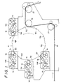
- a blanket cylinder 11 has its outer periphery equipped with a plurality of (10 units of in the illustrated embodiment) blankets 12a-12j which are spaced in a circumferential direction thereof, and the blanket cylinder 11 is rotationally driven in an arrow direction by a drive source (not shown).
- a plurality of (4 units of in the illustrated embodiment) block units 13a-13d are disposed to be spaced around the outer peripheral surface of the blanket cylinder 11.
- Each block unit 13 includes a plate cylinder 14 which becomes separately in rotational contact with each blanket 12 at the rotation of the blanket cylinder 11.
- the plate cylinder 14 can be adjusted its position in any of directions including the circumferential direction (rotational direction), the axial direction (axial lengthwise direction), and the twisted direction (center line's inclined deflection direction).
- Each block unit 13 is furnished with an ink supplying unit for supplying an ink to the plate cylinder 14.
- the ink supplying unit comprises an ink reservoir 15, an ink roller 16, a priming roller 17, and a group of kneading rollers 18. Then a layer of printing ink is formed on the block of each plate cylinder 14. For this reason, a passing of the blanket 12 of the blanket cylinder 11 being rotated along each plate cylinder 14 of the block units 13 causes a transition of a layer of printing ink from the plate cylinder 14 onto the surface of the blanket 12, whereby such a series of consecutive passing thereof along a plurality of block units 13a-13d allows multilayer of printing ink to be coated onto the surface of the blankets 12 respectively.
- the impression cylinder 19 is disposed between the last block unit 13d and the first block unit 13a relatively to the rotational direction of the blanket cylinder 11. Namely, upon completion of providing each blanket 12 of the blanket cylinder 11 with a multilayer of printing ink as the result that the transition of a layer ot the printing ink has been step by step made from each block unit 13, each blanket 12 comes to face the impression cylinder 19.
- a strip of continuous base paper 20 is supplied through and between the impression cylinder 19 and the blanket cylinder 11 by a paper feed device.
- the paper feed device comprises a first feed roller 21 disposed under the impression cylinder 19 and a second feed roller 22 disposed at a position following the rotational direction of the impression cylinder 19.
- These feed rollers 21 and 22 are, as shown in Fig. 2, rotationally driven by servo-motors 23 and 24 acting as drive sources thereof.
- the strip of base paper 20, continuously drawn out, is wound around the first feed roller 21, the impression cylinder 19, and the second feed roller 22, and is transferred in an arrow direction along the rotational direction of both the feed rollers 21 and 22.
- a synthetic resin film may be used as the base paper 20.
- a rotation of the blanket cylinder 11 permits each blanket 12 to pass the block units 13 from the first block unit 13a to the last block unit 13d, whereby 4 kinds or 4 colors of printing ink in total are transited from the corresponding 4 plate cylinders 14 onto each blanket 12, then a coated multilayer of printing ink is formed on the surface of each blanket 12.
- said multilayer of printing ink coated on the blanket 12 is at a stroke transited to the base paper 20 which is being transferred along the surface of the impression cylinder 19 by means of the feed rollers 21 and 22, thereby printing such a multiple printed layer 25 on the base paper 20.
- the blanket cylinder 11 may be equipped with a multiplicity of blankets 12a-12j to a maximum limit, it is possible to minimize a length of the interval between the adjacent blankets 12a and 12b, i.e. a length of the neutral parts 26 (as shown in Fig. 2) where the printing process is not performed.
- the reversive rotation controlling means 27 for the feed rollers 21 and 22 is preferably provided.
- the reversive rotation controlling means 27 can reversively rotate finely the servo-motors 23 and 24 constituting the drive sources for the feed rollers 21 and 22 respectively, when the blanket 12 of the blanket cylinder 11 passes the impression cylinder 19.
- the reversive rotation controlling means 27 can reversively rotate finely the servo-motors 23 and 24 constituting the drive sources for the feed rollers 21 and 22 respectively, when the blanket 12 of the blanket cylinder 11 passes the impression cylinder 19.
- the reversive rotation controlling means 27 includes a servo-mechanism comprising a sensor 28 for detecting a rotational position of the blanket 12 of the blanket cylinder 11, a microcomuter 29 which inputs a signal from the sensor 28 into an input port 29a and issues a specified control signal from an output port 29b, a converter 30 for making D/A conversion of the control signal, and a drive unit 31 which is actuated in response of its receipt of the resulting signal.
- the microcomputer 29 puts into memory a series of information concerning the processes where while, when the printed layer 25 is transited from the blanket 12 onto the base paper 20, i.e.
- the feed rollers 21 and 22 are rotated by a predetermined rotational distance at the specified speed, when a detecting signal that the blanket 12 has completed its passage along the impression cylinder 19 is issued from the sensor 28, i.e. just when the printing process has been completed, the feed rollers 21 and 22 are reversively rotated to a fine extent. That enables the drive unit 31 to rotate the servo-motors 23 and 22 in a reversive/forward manner in accordance with the information.
- the impression cylinder 19 faces the neutral part 26 so that the base paper 20 gives rise to relatively larger gap between the surfaces of impression cylinder 19 and blanket 12 through which the base paper 20 is fed, whereby such a reversive rotation thereof does not give a damage to the base paper 20.
- further accepted modification of the structure may be that: The base paper 20 makes a retreat, while it slips on the impression cylinder 19 being stopped.
- the impression cylinder 19 may be adapted to be freely rotatable so that it is reversively rotated following to the retreat of the base paper 20.
- a mechanism of driving the impression cylinder 19 to rotate reversively the same in a positive manner by the amount necessary for the retreat of the base paper 20 may be provided.
- a rotational frequency of driving the servo-motors 23 and 24 is determined so that the feeding speed of the base paper 20 may be synchronized with the peripheral rotating speed of the blanket cylinder 11.
- Fig. 3 illustrates the conventionally known multiple printing press for offset printing.
- a plurality of printing units 2a, 2b and 2c are disposed in series relatively to a strip of base paper 1 which is transferred by a paper feed device (not shown).
- Each printing unit 2 has a blanket cylinder 3 and an impression cylinder 4 between which the base paper 1 is interposed, the blanket cylinder 3 becoming in contact with a plate cylinder 5.
- the ink supplying means 6 is combined with the plate cylinder 5.
- the known printing press adopts an arrangement in which a layer of ink formed on the surface of the plate cylinder 5 is transited onto the blanket of the blanket cylinder 3 and is further transited from the blanket onto the paper 1, thereby performing the printing thereon.
- the continuous multiple printing made by means of a plurality of printing units 2a, 2b and 2c which are disposed in series relatively to the transferring direction of the base paper 1, gives rise to shear in multiple printing with respect to the multilayer of ink to be printed. That is because a fact that the base paper 1 being transferred is furnished with a specified tension by the paper feed device, it may cause the base paper 1 to be expanded between both the printing units 2a and 2b (or between 2b and 2c).
- an expansion or contraction degree of the base paper 1 may be refinedly changed in response to a change in humidity, after all, it is impossible that the layers of ink transited onto the base paper 1 from each blanket cylinder 3 of the units 2a, 2b and 2c are fully exactly brought in line with one another without incurring the shear therein.
- the interval among the printing units 2a, 2b and 2c is fixed in the printing press, the interval between the front printed part and the rear printed part on the base paper 1 is constant, such an interval being unable to be changed. Ordinarily, a larger blank space takes place between the first printed part and the following printed part, resulting in a wasteful space on the base paper 1. Therefore, generally, in such a series type printing press as shown in Fig. 3, the diameter of the plate cylinder 3 and the dimension of the block thereon are set to the specified version, and the dimension of the block (printed part) cannot be changed.
- a simple process wherein the base paper 20 is not needed to be supplied and the estimated alignment is performed on the blanket cylinder 11 may meet the requirements for the estimated alignment for the multiple printing and/or the multicolor printing. Namely, while the blanket cylinder 11 is being rotated, the layer of printing ink is being continuously transited from the plate cylinders 14 of the block units 13a-13d onto the blankets 12 respectively, then the multilayer of printing ink is coated on each blanket 12. At that time, a visual inspection of the layer of printing ink may enable it to be judged whether the pertinent estimated alignment is proper or not.
- any positional shear is found in the layers of printing ink which are coated on the blanket 12, it may be satisfactory that the adjustment is made as to one or all of positional directions including the circumferential direction (rotational direction), the axial direction (axially lengthwise direction), and the twisted direction (center line's inclined displacement direction) of the plate cylinder 14 of the block unit 13, to which the positional shear is ascribed.
- the vertical coating state of the layers of printing ink transited onto the blanket 12 from the block units 13a-13d is again confirmed whether it gives rise to the positional shear or not. For this reason, the estimated alignment of the present invention can be entirely effected simply on the blankets 12, such adjusting works being able to be executed without a need of supplying the base paper 20.
- the next process is to execute the printing work with the base paper 20 being supplied.
- the multilayer of printing ink is coated as desired on the blanket 12 where the estimated alignment has been finished in advance and the layers has been prepared as a printed layers 25 to be printed on the base paper 20, such prepared multilayer of printing ink is at a stroke transited and printed onto the base paper 20 on the impression cylinder 19, whereby any positional shear among the layers of printing ink does not take place.
- the aforementioned reverse rotation controlling means 27 causes the feed rollers 21 and 22 to be reversively rotated to a fine extent so as to retreat the base paper 20 by a necessary distance and, subsequently, the feed rollers 21 and 22 to be forwardly rotated so as to perform the next printing process through the following blanket 12 onto the base paper 20, an interval S between the printed layers 25 and 25 which are repeatedly printed on the base paper 20 can be made smaller than the dimension of the neutral part 26 of the blanket cylinder 11.
- the interval S between the printed layers 25 and 25 can be set to the desired narrower dimension by simply changing the amount of rotating reversively the feed rollers 21 and 22.
- the estimated alignment of the layers of printing ink can be performed on the blanket cylinder 11 with the visual inspection of the coating state thereof being concurrently made.
- the trial printing is executed with the base paper being supplied, whenever the adjusting work for the estimated alignment is performed. Therefore, the base paper is not wastefuly consumed so that the entire process becomes economical reality.
- the layers of printing ink are desiredly coated on the blanket 12 in advance bypassing the blanket 12 along each of a plurality of block units 13, and the prepared multilayer of printing ink is at a stroke transited and printed onto the base paper 20, even if an expansion or contraction of the base paper 20 being transferred takes place, any shear in printing is not incurred in the coating state of the printed layers 25 on the base paper.
- a provision of the reversive rotation controlling means 27 realizes an effect wherein the interval S between the printed layers 25 and 25 which are repeatedly printed on the base paper 20 can be made smaller as desired, thereby enabling the printing process in which the aforementioned interval becomes close.
Landscapes
- Engineering & Computer Science (AREA)
- Mechanical Engineering (AREA)
- Rotary Presses (AREA)
- Inking, Control Or Cleaning Of Printing Machines (AREA)
Applications Claiming Priority (2)
| Application Number | Priority Date | Filing Date | Title |
|---|---|---|---|
| JP2088961A JPH03286863A (ja) | 1990-04-02 | 1990-04-02 | 多重印刷装置 |
| JP88961/90 | 1990-04-02 |
Publications (1)
| Publication Number | Publication Date |
|---|---|
| EP0452535A1 true EP0452535A1 (fr) | 1991-10-23 |
Family
ID=13957430
Family Applications (1)
| Application Number | Title | Priority Date | Filing Date |
|---|---|---|---|
| EP90111788A Withdrawn EP0452535A1 (fr) | 1990-04-02 | 1990-06-21 | Presse à impression multiple |
Country Status (3)
| Country | Link |
|---|---|
| EP (1) | EP0452535A1 (fr) |
| JP (1) | JPH03286863A (fr) |
| KR (1) | KR910018177A (fr) |
Families Citing this family (1)
| Publication number | Priority date | Publication date | Assignee | Title |
|---|---|---|---|---|
| JP6143471B2 (ja) * | 2013-01-18 | 2017-06-07 | 株式会社フジクラ | 回路形成装置及び回路形成方法 |
Citations (9)
| Publication number | Priority date | Publication date | Assignee | Title |
|---|---|---|---|---|
| BE356402A (fr) * | ||||
| US1379365A (en) * | 1920-11-13 | 1921-05-24 | Oswald R Schultz | Method of and apparatus for making multicolor prints |
| FR545039A (fr) * | 1921-12-23 | 1922-10-04 | Anciens Etablissements Marinon | Machine roto-calco à couleurs pour imprimer la toile cirée ou autre article |
| FR2242243A1 (en) * | 1973-08-27 | 1975-03-28 | Schulz Juergen | Web dry offset printing press - has plate cylinder with printing block attachable to frame holding blanket cylinder |
| GB2106035A (en) * | 1981-09-09 | 1983-04-07 | Koenig & Bauer Ag | Printing on webs |
| JPS59133056A (ja) * | 1983-01-20 | 1984-07-31 | Osaka Shiiring Insatsu Kk | オフセツト多色印刷機 |
| US4491071A (en) * | 1981-04-15 | 1985-01-01 | M.A.N.-Roland Druckmaschinen Aktiengesellschaft | Arrangement for securing skew adjustment of a plate cylinder in a sheet-fed rotary printing press |
| JPS62116148A (ja) * | 1985-11-15 | 1987-05-27 | Toray Ind Inc | オフセット印刷機用の連続紙間欠送り制御装置 |
| EP0353652A2 (fr) * | 1988-08-02 | 1990-02-07 | RENA INFORMATIONSTECHNIK GMBH & CO. KG | Dispositif supplémentaire pour montage sur une machine d'impression offset |
Family Cites Families (2)
| Publication number | Priority date | Publication date | Assignee | Title |
|---|---|---|---|---|
| JPS62191147A (ja) * | 1986-02-18 | 1987-08-21 | Mitsubishi Heavy Ind Ltd | 間欠紙送り印刷機 |
| JPH0275561A (ja) * | 1988-09-13 | 1990-03-15 | Sanjiyou Kikai Seisakusho:Kk | 帯状印刷物の給送装置 |
-
1990
- 1990-04-02 JP JP2088961A patent/JPH03286863A/ja active Pending
- 1990-06-21 EP EP90111788A patent/EP0452535A1/fr not_active Withdrawn
- 1990-06-25 KR KR1019900009415A patent/KR910018177A/ko not_active Ceased
Patent Citations (9)
| Publication number | Priority date | Publication date | Assignee | Title |
|---|---|---|---|---|
| BE356402A (fr) * | ||||
| US1379365A (en) * | 1920-11-13 | 1921-05-24 | Oswald R Schultz | Method of and apparatus for making multicolor prints |
| FR545039A (fr) * | 1921-12-23 | 1922-10-04 | Anciens Etablissements Marinon | Machine roto-calco à couleurs pour imprimer la toile cirée ou autre article |
| FR2242243A1 (en) * | 1973-08-27 | 1975-03-28 | Schulz Juergen | Web dry offset printing press - has plate cylinder with printing block attachable to frame holding blanket cylinder |
| US4491071A (en) * | 1981-04-15 | 1985-01-01 | M.A.N.-Roland Druckmaschinen Aktiengesellschaft | Arrangement for securing skew adjustment of a plate cylinder in a sheet-fed rotary printing press |
| GB2106035A (en) * | 1981-09-09 | 1983-04-07 | Koenig & Bauer Ag | Printing on webs |
| JPS59133056A (ja) * | 1983-01-20 | 1984-07-31 | Osaka Shiiring Insatsu Kk | オフセツト多色印刷機 |
| JPS62116148A (ja) * | 1985-11-15 | 1987-05-27 | Toray Ind Inc | オフセット印刷機用の連続紙間欠送り制御装置 |
| EP0353652A2 (fr) * | 1988-08-02 | 1990-02-07 | RENA INFORMATIONSTECHNIK GMBH & CO. KG | Dispositif supplémentaire pour montage sur une machine d'impression offset |
Non-Patent Citations (2)
| Title |
|---|
| PATENT ABSTRACTS OF JAPAN, vol. 11, no. 333 (M-637)[2780] November 30, 1987; & JP-A-62 116 148 (TORAY IND INC.) May 27, 1987 * |
| PATENT ABSTRACTS OF JAPAN, vol. 8, no. 262 (M-341)[1699] November 30, 1984; & JP-A-59 133 056 (OOSAKA SHIRING INSATSU) July 31, 1984 * |
Also Published As
| Publication number | Publication date |
|---|---|
| KR910018177A (ko) | 1991-11-30 |
| JPH03286863A (ja) | 1991-12-17 |
Similar Documents
| Publication | Publication Date | Title |
|---|---|---|
| US6382092B1 (en) | Printing machine with exchangeable ink application means | |
| US4660470A (en) | Inking unit pre-adjustment method | |
| US6367385B2 (en) | Ink film thickness control method and apparatus for multi-color printing press | |
| GB2314292A (en) | A method and printing machine for printing a material web | |
| US5148747A (en) | Process for setting a production run ink zone profile | |
| US5243904A (en) | Stencil printing with no back contamination | |
| US6279474B1 (en) | Method and device for transferring ink in a printing unit of an offset printing press | |
| US6453812B1 (en) | Ink supply control device for printing machines and a method therefor | |
| EP0452535A1 (fr) | Presse à impression multiple | |
| US6810810B2 (en) | Method and device for adjusting a quantity of ink supplied to an impression cylinder of a printing machine | |
| JP3488866B2 (ja) | 金属板の印刷方法およびその装置 | |
| US4603631A (en) | Perfecting printing process and apparatus for a sheet-fed offset press | |
| US20110011292A1 (en) | Method for Changing Edition on a Rotary Press | |
| US5778781A (en) | Method and apparatus for printing on opposite sides of a web | |
| US5159878A (en) | System for moving a plate cylinder relative to a blanket cylinder | |
| US5265527A (en) | Offset printing press with emulsification control | |
| US7055433B1 (en) | Method of operation of a printing unit and printing unit for offset machine | |
| EP0993375B1 (fr) | Impression flexographique selective avec un rouleau d'encrage mobile | |
| JPH07266548A (ja) | 輪転印刷機 | |
| DE60114481T2 (de) | Schablonendruckmaschine und Druckschablone-Überführungsverfahren | |
| JPH0368826B2 (fr) | ||
| JP2005081819A (ja) | 間欠オフセット印刷機 | |
| CS250216B2 (en) | Equipment for lithography or gravure printing | |
| JP3359768B2 (ja) | 熱転写記録装置 | |
| JP4776339B2 (ja) | 印刷機および印刷機の運転方法 |
Legal Events
| Date | Code | Title | Description |
|---|---|---|---|
| PUAI | Public reference made under article 153(3) epc to a published international application that has entered the european phase |
Free format text: ORIGINAL CODE: 0009012 |
|
| AK | Designated contracting states |
Kind code of ref document: A1 Designated state(s): DE FR GB IT NL |
|
| STAA | Information on the status of an ep patent application or granted ep patent |
Free format text: STATUS: THE APPLICATION IS DEEMED TO BE WITHDRAWN |
|
| 18D | Application deemed to be withdrawn |
Effective date: 19920424 |