EP0452555A1 - Connecteur, notamment connecteur hermaphrodite - Google Patents
Connecteur, notamment connecteur hermaphrodite Download PDFInfo
- Publication number
- EP0452555A1 EP0452555A1 EP90124141A EP90124141A EP0452555A1 EP 0452555 A1 EP0452555 A1 EP 0452555A1 EP 90124141 A EP90124141 A EP 90124141A EP 90124141 A EP90124141 A EP 90124141A EP 0452555 A1 EP0452555 A1 EP 0452555A1
- Authority
- EP
- European Patent Office
- Prior art keywords
- contacts
- plug
- frame
- cover
- halves
- Prior art date
- Legal status (The legal status is an assumption and is not a legal conclusion. Google has not performed a legal analysis and makes no representation as to the accuracy of the status listed.)
- Granted
Links
- 230000010196 hermaphroditism Effects 0.000 title claims description 24
- 230000002093 peripheral effect Effects 0.000 claims 1
- 230000037431 insertion Effects 0.000 abstract description 4
- 238000003780 insertion Methods 0.000 abstract description 4
- 230000013011 mating Effects 0.000 description 15
- 238000010079 rubber tapping Methods 0.000 description 4
- 238000001746 injection moulding Methods 0.000 description 2
- 238000002788 crimping Methods 0.000 description 1
- 230000001934 delay Effects 0.000 description 1
- 230000002349 favourable effect Effects 0.000 description 1
- 238000004519 manufacturing process Methods 0.000 description 1
- 239000000243 solution Substances 0.000 description 1
Images


Classifications
-
- H—ELECTRICITY
- H01—ELECTRIC ELEMENTS
- H01R—ELECTRICALLY-CONDUCTIVE CONNECTIONS; STRUCTURAL ASSOCIATIONS OF A PLURALITY OF MUTUALLY-INSULATED ELECTRICAL CONNECTING ELEMENTS; COUPLING DEVICES; CURRENT COLLECTORS
- H01R24/00—Two-part coupling devices, or either of their cooperating parts, characterised by their overall structure
- H01R24/84—Hermaphroditic coupling devices
-
- H—ELECTRICITY
- H01—ELECTRIC ELEMENTS
- H01R—ELECTRICALLY-CONDUCTIVE CONNECTIONS; STRUCTURAL ASSOCIATIONS OF A PLURALITY OF MUTUALLY-INSULATED ELECTRICAL CONNECTING ELEMENTS; COUPLING DEVICES; CURRENT COLLECTORS
- H01R13/00—Details of coupling devices of the kinds covered by groups H01R12/70 or H01R24/00 - H01R33/00
- H01R13/02—Contact members
- H01R13/28—Contacts for sliding cooperation with identically-shaped contact, e.g. for hermaphroditic coupling devices
Definitions
- the invention relates to a connector, in particular hermaphrodite connector, with a housing and inserted therein, elongated contacts having a connection end and a plug end facing the plug face of the housing, the housing overlapping the connection end of the contacts and provided with at least one strain relief clamp for connection cables is.
- Such connectors are known in practice as charging connectors. They are used to transmit high current between the charging station and battery of battery-operated vehicles, and between the battery and engine of such a vehicle.
- connectors which consist of two housing halves screwed together, the contacts being inserted into one housing half for assembly of the connectors, after which the other housing half is then placed over it and screwed to the first housing half.
- connector housings are also known in which the contacts can be inserted in the direction of their longitudinal extent, locking pins or clips inserted into the housing transversely to the plugging direction then having to be used in order to lock the contacts in the plugging direction. This is not always easy because the contacts can twist about their longitudinal axis and are only held in position by the locking pins.
- these housings also consist of two together screwed housing halves.
- the assembly of the connectors described above takes place in two stages.
- the first stage the pre-assembly, at least the housing halves have to be screwed together, but it is also useful in the known connectors to use the contacts and the fastening elements so that the fastening elements, which are relatively small, are not lost when the connectors are shipped.
- the second assembly stage which the customer, d. H. at the vehicle manufacturer, the connectors must then be partially taken apart again, after which the contacts are connected to the ends of the connecting cables and inserted back into the housing.
- work has to be carried out twice in the first and in the second assembly stage, which increases the cost of using such connectors. If you want to avoid this duplication of work, the customer receives a large number of small components, some of which he does not know exactly how to assemble. This also results in delays that make the use of such connectors more expensive.
- At least one stop shoulder is formed on the contacts between their plug end and their connection end that the housing is divided transversely to the direction of insertion and a frame with the mating face, in which the contacts are inserted with their plug end from the side facing away from the mating face until the abutment shoulder rests against the frame, and two cover halves articulated and closable on the side of the frame facing away from the mating face via a lid hinge each has, which cover the connection ends of the contacts in the closed state, and that the cover hinges each have at least one pull tab and one pressure tab which are attached to the side of the cover facing the frame, the pull tab being held on the side of the frame facing away from the mating face , while the pressure tab on the side of the contact shoulder facing away from the frame engages behind.
- the housing can then be constructed in three parts, the two cover halves being identical, so that only two injection molding tools are required if the housing is produced by injection molding, as is customary.
- the free end of the pressure tabs is adapted to the circumferential shape of the contacts and rests on the contacts in the closed state of the cover halves. This has the advantage that the pressure straps press the neck halves with the pull straps into the locking recesses in the frame, so that the hinges are braced.
- the pressure tabs point obliquely to the contacts in the direction of insertion and are designed to be elastically bendable, so that the contacts between the cover halves and the frame are fixed in position, and the hinges are elastically tensioned.
- the webs laterally frame the lid halves, since then lateral forces which, for. B. can occur when a connector falls down, do not attack directly on the cover halves.
- catches of the webs are designed as catch recesses, while the counter catches are designed as catch wedges which engage in the catch recesses, it can always be seen from the outside whether the cover halves are correctly engaged or not.
- the strain relief clamp for the connecting cable consists of two halves, one half being articulated on the back of a cover half facing away from the frame via an elastically bendable tabs.
- the two cover halves are also held in the closed state of the connector by the strain relief clamp, the halves of which are usually held together by screws.
- the latching connection between the cover halves and the lateral webs is therefore essentially only an assembly aid, which is no longer absolutely necessary when the connector is in use.
- the bendable tab is formed as a strip of the cover surface which is laterally delimited by slots and which extends from approximately the center of the cover surface to the rear of a cover half. This relatively long tab enables the halves of the strain relief clamp to adapt to both relatively thick and relatively thin cables.
- each half of a strain relief clamp can have at least four holes for fastening screws each, which are connected to the four holes in the other half of the clamp are aligned, with two diagonally opposite holes each having a smaller diameter than the other two holes.
- the strain relief clamps can be connected in this way with self-tapping screws, the threaded parts of which cut into the holes of smaller diameter. Since a total of four holes are provided, each clamp half has two large holes that are aligned with two small holes in the other half of the clamp. In this way, the fastening screws can always be screwed into the strain relief clamp from one side, which in turn simplifies assembly.
- the lateral webs of the frame extend as far as between the halves of the strain relief clamp and each have two bores which are aligned with the bores of the clamp halves.
- the covers are additionally fastened to the lateral webs of the frame, so that the hinge for the cover halves is also relieved.
- Hermaphrodite contacts having circular disk segments are formed if triangular cover surfaces are formed on the free-ending edge of the mating face of the frame, which cover the end faces of the mating ends of the hermaphrodite contacts inserted in the connector, and if on the base surface of the mating face from which the mating ends of the contacts emerge until are formed to the free-ended edge of the mating face elevations, which are arranged in front of the open flanks of the mating contacts as contact protection, it is impossible to get fingers at live parts in the mating face of the connector when the connectors are not plugged together.
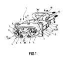
- a connector 1 which has a housing 2 and elongated hermaphrodite contacts 3 inserted therein.
- this connector is shown with a view of the mating face 4. It can also be seen there that the hermaphrodite contacts have the shape of two opposing circular segments in cross section, the plug end 5 facing the plug face 4 being covered by triangular cover surfaces 6. In addition to the free flanks 7 of the plug ends 5, up to the end edge of the mating face 4, elevations 8 in the form of pins or the like are provided which, together with the cover surfaces 6, ensure protection against contact and make it impossible to touch the contacts 3.
- the housing 2 of a connector consists of a frame 9, into which the hermaphrodite contacts 3 are inserted from the side opposite the plug face 4, and of two cover halves 10 and 11, which form the connection ends 12 of the hermaphrodite contacts 3 cover and on the back of which the corresponding halves 14 and 15 of a strain relief clamp 13 are attached.
- the lid halves 10 and 11 are hinged to the frame 9.
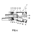
- the hinges comprise a pull tab 16, the free end of which is provided with a locking wedge 17 which engages behind an opening 18 in the frame 9, as can be seen particularly well from the upper half in FIG. 4.
- the hinges include a pressure tab 18 which engages behind an abutment shoulder 20 of the hermaphrodite contacts 3, with which the hermaphrodite contacts 3 are also supported with respect to the frame 9. This can be seen particularly well from FIG. 2.
- the hermaphrodite contacts 3 are axially caught with their contact shoulder 20 between a contact surface of the frame 9 and between the ends of the pressure tabs 19 when the cover halves 10 and 11 are in the closed state shown in FIG. 2.
- the pressure tabs 19 point obliquely forward from the cover halves 10 and 11 in the direction of insertion of the hermaphrodite contacts 3 and are designed to be flexible.
- the free ends of the pressure tabs are adapted to the outer contour of the hermaphrodite contacts and lie on the outer contour of the hermaphrodite contacts 3.
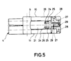
- two lateral webs 21 which extend to the rear are formed on the rear side of the frame 9 facing away from the plug face 4.
- the webs have a vertical section in about the first two thirds and a horizontal section 23 in the last third.
- latching openings 24 are provided which cooperate with corresponding latching wedges 25 arranged laterally on the outer sides of the lid halves when the lid halves are closed (cf. FIG. 5).
- the clamp halves 14 and 15 of the strain relief clamp 13 are arranged on the back of the cover halves 10 and 11, respectively.
- the clamp halves are fastened to the cover half 10 or 11 via a tab 26 which lies in the cover surface of a cover half and extends approximately to the middle of the cover half.
- the tab 26 is formed in that the cover is slotted into the side of the tab 26 up to approximately the center of the cover.
- the clamp halves 14 and 15 are relatively rigid in themselves and have bores 27 and 28 at their ends.
- the holes 27 and 28 lie side by side so that they form the corners of a square.
- the bores 27 have a larger diameter than the bores 28, two bores of the same diameter each lying diagonally opposite one another.
- the clamp halves 14 and 15 are fastened by so-called self-tapping screws which can be inserted through the bores 27 of larger diameter and cut their threads into the edge of the bores 28 of smaller diameter.
- bores 29 are provided which are aligned with the bores 27 and 28 of the cover halves when the cover halves 10 and 11 are attached to the frame 9.
- a frame 9 (see FIG. 6) and two cover halves 10 and 11 (see FIG. 7), as well as two hermaphrodite contacts 3 and two self-tapping screws are required.
- the two cover halves 10 and 11 if necessary at all, are hung with their pull tabs 16 in the openings 18 of the associated frame 9.
- the connector thus prepared then arrives at the customer.
- the customer connects the two hermaphrodite contacts 3 with the ends of the associated connecting cables, which z. B. can be done by squeezing the terminal ends 12.
- the hermaphrodite contacts 3 are then inserted with half-opened cover halves (see FIG. 4 below) in push-through openings of the frame, the elastic pressure tabs 19 being able to deflect upwards and downwards until the hermaphrodite contacts with their contact shoulders 20 after passing the pressure tabs 19 on the frame 9 concerns.
- the hermaphrodite contact must pass a narrow point in the through-opening adapted to the shape of the profile cross section, as a result of which the hermaphrodite contact is automatically aligned in its correct position.
- the pressure tabs 19 then engage behind the contact shoulders 20.
- the cover halves can then simply be pressed together, the lateral locking wedges 25 engaging in the locking openings 24 on the lateral webs of the frame 9, so that the two cover halves 10 and 11 snap together
- the cover surfaces 6 and the elevations 8 do not interfere when plugged together, but they offer effective protection against accidental contact with the contacts.
Landscapes
- Connector Housings Or Holding Contact Members (AREA)
- Coupling Device And Connection With Printed Circuit (AREA)
- Connections By Means Of Piercing Elements, Nuts, Or Screws (AREA)
- Details Of Connecting Devices For Male And Female Coupling (AREA)
Applications Claiming Priority (2)
| Application Number | Priority Date | Filing Date | Title |
|---|---|---|---|
| DE9004383U DE9004383U1 (de) | 1990-04-17 | 1990-04-17 | Steckverbinder, insbesondere Zwittersteckverbinder |
| DE9004383U | 1990-04-17 |
Publications (2)
| Publication Number | Publication Date |
|---|---|
| EP0452555A1 true EP0452555A1 (fr) | 1991-10-23 |
| EP0452555B1 EP0452555B1 (fr) | 1995-03-08 |
Family
ID=6852974
Family Applications (1)
| Application Number | Title | Priority Date | Filing Date |
|---|---|---|---|
| EP90124141A Expired - Lifetime EP0452555B1 (fr) | 1990-04-17 | 1990-12-13 | Connecteur, notamment connecteur hermaphrodite |
Country Status (3)
| Country | Link |
|---|---|
| EP (1) | EP0452555B1 (fr) |
| BG (1) | BG60080B2 (fr) |
| DE (2) | DE9004383U1 (fr) |
Cited By (7)
| Publication number | Priority date | Publication date | Assignee | Title |
|---|---|---|---|---|
| WO1993023897A1 (fr) * | 1992-05-21 | 1993-11-25 | Plantronics, Inc. | Connecteur de cables a debranchement rapide |
| WO1998000887A1 (fr) * | 1996-07-01 | 1998-01-08 | Siemens Aktiengesellschaft | Connecteur a fiches a partie couvercle pouvant etre fermee et procede pour fermer une ligne electrique menant jusqu'a un connecteur a fiches de ce type |
| US5890922A (en) * | 1996-09-11 | 1999-04-06 | The Whitaker Corporation | Electrical connector |
| EP0932224A1 (fr) * | 1998-01-27 | 1999-07-28 | Wilfried Pöllet | Connecteur électrique multi-pole démontable |
| GB2349516A (en) * | 1999-03-17 | 2000-11-01 | Whittaker Corp The | Contact-retaining shroud for electrical connector |
| CN109524843A (zh) * | 2019-01-07 | 2019-03-26 | 东莞市联纲光电科技有限公司 | 快速连接器 |
| CN113451822A (zh) * | 2021-07-13 | 2021-09-28 | 四川华丰科技股份有限公司 | 一体式大电流连接器 |
Families Citing this family (1)
| Publication number | Priority date | Publication date | Assignee | Title |
|---|---|---|---|---|
| DE102020134071A1 (de) | 2020-12-17 | 2022-06-23 | Bayerische Motoren Werke Aktiengesellschaft | Erweiterungsmodul für ein Fahrzeug, System mit einem Erweiterungsmodul, sowie Fahrzeug mit einer Aufnahme für ein Erweiterungsmodul |
Citations (2)
| Publication number | Priority date | Publication date | Assignee | Title |
|---|---|---|---|---|
| US3794957A (en) * | 1973-01-22 | 1974-02-26 | Anderson Power Products | Plural-poled, genderless electrical connector |
| FR2337951A1 (fr) * | 1976-01-07 | 1977-08-05 | Amp Inc | Connecteur electrique hermaphrodite |
-
1990
- 1990-04-17 DE DE9004383U patent/DE9004383U1/de not_active Expired - Lifetime
- 1990-12-13 DE DE59008662T patent/DE59008662D1/de not_active Expired - Fee Related
- 1990-12-13 EP EP90124141A patent/EP0452555B1/fr not_active Expired - Lifetime
-
1991
- 1991-04-15 BG BG094260A patent/BG60080B2/bg unknown
Patent Citations (2)
| Publication number | Priority date | Publication date | Assignee | Title |
|---|---|---|---|---|
| US3794957A (en) * | 1973-01-22 | 1974-02-26 | Anderson Power Products | Plural-poled, genderless electrical connector |
| FR2337951A1 (fr) * | 1976-01-07 | 1977-08-05 | Amp Inc | Connecteur electrique hermaphrodite |
Non-Patent Citations (1)
| Title |
|---|
| Elektrische Energie Technik EET, vol. 34, no. 6, Dezember 1989, Heidelberg Seite 83 "Huckepack-Stecker" * |
Cited By (9)
| Publication number | Priority date | Publication date | Assignee | Title |
|---|---|---|---|---|
| WO1993023897A1 (fr) * | 1992-05-21 | 1993-11-25 | Plantronics, Inc. | Connecteur de cables a debranchement rapide |
| AU665103B2 (en) * | 1992-05-21 | 1995-12-14 | Plantronics, Inc. | Quick disconnect wiring connector |
| WO1998000887A1 (fr) * | 1996-07-01 | 1998-01-08 | Siemens Aktiengesellschaft | Connecteur a fiches a partie couvercle pouvant etre fermee et procede pour fermer une ligne electrique menant jusqu'a un connecteur a fiches de ce type |
| US5890922A (en) * | 1996-09-11 | 1999-04-06 | The Whitaker Corporation | Electrical connector |
| EP0932224A1 (fr) * | 1998-01-27 | 1999-07-28 | Wilfried Pöllet | Connecteur électrique multi-pole démontable |
| GB2349516A (en) * | 1999-03-17 | 2000-11-01 | Whittaker Corp The | Contact-retaining shroud for electrical connector |
| GB2349516B (en) * | 1999-03-17 | 2003-02-12 | Whittaker Corp The | Shroud for electrical connector |
| CN109524843A (zh) * | 2019-01-07 | 2019-03-26 | 东莞市联纲光电科技有限公司 | 快速连接器 |
| CN113451822A (zh) * | 2021-07-13 | 2021-09-28 | 四川华丰科技股份有限公司 | 一体式大电流连接器 |
Also Published As
| Publication number | Publication date |
|---|---|
| DE59008662D1 (de) | 1995-04-13 |
| EP0452555B1 (fr) | 1995-03-08 |
| BG60080B2 (bg) | 1993-09-30 |
| DE9004383U1 (de) | 1991-08-29 |
Similar Documents
| Publication | Publication Date | Title |
|---|---|---|
| DE69520197T2 (de) | Anordnung zur schwimmenden Montage eines elektrischen Verbinders an einer Platte | |
| DE69020827T2 (de) | Steckvorrichtung für Einspritzdüsen für eine Brennkraftmaschine und dabei verwendetes Kontaktelement. | |
| DE3903839C2 (fr) | ||
| EP3734768B1 (fr) | Connecteur enfichable d'un raccord enfichable électrique ainsi que raccord enfichable électrique ainsi formé | |
| DE69508569T2 (de) | Sekundär anschluss verriegelungs element | |
| EP3734771B1 (fr) | Ensemble comprenant un connecteur électrique et un élément fonctionnel | |
| DE69705658T2 (de) | Modularer Aufbau, bestehend aus mehreren Einheiten, mit den entsprechenden Steckverbindern | |
| EP3613106A1 (fr) | Châssis-support pour un connecteur électrique et procédé de montage | |
| DE29508095U1 (de) | Modulares Steckverbindersystem | |
| DE102019104559A1 (de) | Halterahmen für eine Steckverbinder | |
| DE102019135726A1 (de) | Halterahmen für einen Steckverbinder | |
| EP4241340A1 (fr) | Module de connecteur | |
| EP0452555B1 (fr) | Connecteur, notamment connecteur hermaphrodite | |
| DE69310439T2 (de) | Verriegelbarer elektrischer Verbinderanordnung | |
| DE3313144C2 (de) | Elektrischer Steckverbinder | |
| EP2475057B2 (fr) | Dispositif de support de câble | |
| DE3886931T2 (de) | Zeitgeber mit mehrteiligem gehäuse und abtrennender deckscheibe mit schnappschlossverbindung. | |
| DE3643087A1 (de) | Schnellkupplungsklemme fuer den klemmenpol eines elektrischen geraetes | |
| DE2855685A1 (de) | Elektrischer verbinder mit verblendeter vorderseite | |
| DE102017109899A1 (de) | Elektrischer Verbinder | |
| DE102021105967A1 (de) | Zusammenstellbarer Steckverbinder-Kombinationsrahmen | |
| DE69622082T2 (de) | Verbindungsmodul mit abnehmbaren Kontakten und Anwendung in Verbindungsleisten | |
| DE3522797A1 (de) | Elektrische vielfachsteckvorrichtung | |
| DE69305021T2 (de) | Elektrischer Verbinder | |
| EP0757409A1 (fr) | Connecteur électrique |
Legal Events
| Date | Code | Title | Description |
|---|---|---|---|
| PUAI | Public reference made under article 153(3) epc to a published international application that has entered the european phase |
Free format text: ORIGINAL CODE: 0009012 |
|
| 17P | Request for examination filed |
Effective date: 19910411 |
|
| AK | Designated contracting states |
Kind code of ref document: A1 Designated state(s): DE FR GB IT SE |
|
| ITCL | It: translation for ep claims filed |
Representative=s name: GIUGNI S.R.L. |
|
| EL | Fr: translation of claims filed | ||
| RAP1 | Party data changed (applicant data changed or rights of an application transferred) |
Owner name: REMA-LIPPRANDT GMBH & CO. KG Owner name: SCHALTBAU AKTIENGESELLSCHAFT |
|
| 17Q | First examination report despatched |
Effective date: 19940222 |
|
| GRAA | (expected) grant |
Free format text: ORIGINAL CODE: 0009210 |
|
| AK | Designated contracting states |
Kind code of ref document: B1 Designated state(s): DE FR GB IT SE |
|
| ET | Fr: translation filed | ||
| REF | Corresponds to: |
Ref document number: 59008662 Country of ref document: DE Date of ref document: 19950413 |
|
| GBT | Gb: translation of ep patent filed (gb section 77(6)(a)/1977) |
Effective date: 19950322 |
|
| ITF | It: translation for a ep patent filed | ||
| PLBE | No opposition filed within time limit |
Free format text: ORIGINAL CODE: 0009261 |
|
| STAA | Information on the status of an ep patent application or granted ep patent |
Free format text: STATUS: NO OPPOSITION FILED WITHIN TIME LIMIT |
|
| 26N | No opposition filed | ||
| PGFP | Annual fee paid to national office [announced via postgrant information from national office to epo] |
Ref country code: GB Payment date: 19971121 Year of fee payment: 8 |
|
| PGFP | Annual fee paid to national office [announced via postgrant information from national office to epo] |
Ref country code: FR Payment date: 19971215 Year of fee payment: 8 |
|
| PGFP | Annual fee paid to national office [announced via postgrant information from national office to epo] |
Ref country code: SE Payment date: 19971219 Year of fee payment: 8 |
|
| PG25 | Lapsed in a contracting state [announced via postgrant information from national office to epo] |
Ref country code: GB Free format text: LAPSE BECAUSE OF NON-PAYMENT OF DUE FEES Effective date: 19981213 |
|
| PG25 | Lapsed in a contracting state [announced via postgrant information from national office to epo] |
Ref country code: SE Free format text: LAPSE BECAUSE OF NON-PAYMENT OF DUE FEES Effective date: 19981214 |
|
| PGFP | Annual fee paid to national office [announced via postgrant information from national office to epo] |
Ref country code: DE Payment date: 19990127 Year of fee payment: 9 |
|
| GBPC | Gb: european patent ceased through non-payment of renewal fee |
Effective date: 19981213 |
|
| PG25 | Lapsed in a contracting state [announced via postgrant information from national office to epo] |
Ref country code: FR Free format text: LAPSE BECAUSE OF NON-PAYMENT OF DUE FEES Effective date: 19990831 |
|
| REG | Reference to a national code |
Ref country code: FR Ref legal event code: ST |
|
| PG25 | Lapsed in a contracting state [announced via postgrant information from national office to epo] |
Ref country code: DE Free format text: LAPSE BECAUSE OF NON-PAYMENT OF DUE FEES Effective date: 20001003 |
|
| PG25 | Lapsed in a contracting state [announced via postgrant information from national office to epo] |
Ref country code: IT Free format text: LAPSE BECAUSE OF NON-PAYMENT OF DUE FEES Effective date: 20051213 |