EP0452558B1 - Elément échangeur planair - Google Patents
Elément échangeur planair Download PDFInfo
- Publication number
- EP0452558B1 EP0452558B1 EP90124665A EP90124665A EP0452558B1 EP 0452558 B1 EP0452558 B1 EP 0452558B1 EP 90124665 A EP90124665 A EP 90124665A EP 90124665 A EP90124665 A EP 90124665A EP 0452558 B1 EP0452558 B1 EP 0452558B1
- Authority
- EP
- European Patent Office
- Prior art keywords
- metal plate
- room
- heat exchange
- heat
- frame
- Prior art date
- Legal status (The legal status is an assumption and is not a legal conclusion. Google has not performed a legal analysis and makes no representation as to the accuracy of the status listed.)
- Expired - Lifetime
Links
- 229910052751 metal Inorganic materials 0.000 claims abstract description 31
- 239000002184 metal Substances 0.000 claims abstract description 31
- 238000001816 cooling Methods 0.000 claims abstract description 11
- 238000009413 insulation Methods 0.000 claims description 8
- 239000006260 foam Substances 0.000 claims description 3
- 238000004378 air conditioning Methods 0.000 claims description 2
- 229910052500 inorganic mineral Inorganic materials 0.000 claims description 2
- 239000000463 material Substances 0.000 claims description 2
- 239000011707 mineral Substances 0.000 claims description 2
- 229930014626 natural product Natural products 0.000 claims description 2
- 239000003973 paint Substances 0.000 claims description 2
- 239000000126 substance Substances 0.000 claims description 2
- 229920002994 synthetic fiber Polymers 0.000 claims description 2
- 239000004753 textile Substances 0.000 claims description 2
- 230000015572 biosynthetic process Effects 0.000 claims 1
- 229920003002 synthetic resin Polymers 0.000 claims 1
- 239000000057 synthetic resin Substances 0.000 claims 1
- 238000010438 heat treatment Methods 0.000 description 8
- 229910052782 aluminium Inorganic materials 0.000 description 3
- XAGFODPZIPBFFR-UHFFFAOYSA-N aluminium Chemical compound [Al] XAGFODPZIPBFFR-UHFFFAOYSA-N 0.000 description 3
- 238000010276 construction Methods 0.000 description 3
- 239000012876 carrier material Substances 0.000 description 2
- 230000002787 reinforcement Effects 0.000 description 2
- 238000004026 adhesive bonding Methods 0.000 description 1
- 239000003795 chemical substances by application Substances 0.000 description 1
- 238000005253 cladding Methods 0.000 description 1
- 239000011888 foil Substances 0.000 description 1
- 238000009434 installation Methods 0.000 description 1
- 238000004519 manufacturing process Methods 0.000 description 1
- 238000000034 method Methods 0.000 description 1
- 239000011505 plaster Substances 0.000 description 1
- 239000000088 plastic resin Substances 0.000 description 1
- 238000005476 soldering Methods 0.000 description 1
- 239000012209 synthetic fiber Substances 0.000 description 1
- XLYOFNOQVPJJNP-UHFFFAOYSA-N water Substances O XLYOFNOQVPJJNP-UHFFFAOYSA-N 0.000 description 1
- 238000003466 welding Methods 0.000 description 1
Images
Classifications
-
- F—MECHANICAL ENGINEERING; LIGHTING; HEATING; WEAPONS; BLASTING
- F24—HEATING; RANGES; VENTILATING
- F24D—DOMESTIC- OR SPACE-HEATING SYSTEMS, e.g. CENTRAL HEATING SYSTEMS; DOMESTIC HOT-WATER SUPPLY SYSTEMS; ELEMENTS OR COMPONENTS THEREFOR
- F24D3/00—Hot-water central heating systems
- F24D3/12—Tube and panel arrangements for ceiling, wall, or underfloor heating
- F24D3/16—Tube and panel arrangements for ceiling, wall, or underfloor heating mounted on, or adjacent to, a ceiling, wall or floor
- F24D3/165—Suspended radiant heating ceiling
-
- E—FIXED CONSTRUCTIONS
- E04—BUILDING
- E04B—GENERAL BUILDING CONSTRUCTIONS; WALLS, e.g. PARTITIONS; ROOFS; FLOORS; CEILINGS; INSULATION OR OTHER PROTECTION OF BUILDINGS
- E04B9/00—Ceilings; Construction of ceilings, e.g. false ceilings; Ceiling construction with regard to insulation
- E04B9/22—Connection of slabs, panels, sheets or the like to the supporting construction
- E04B9/28—Connection of slabs, panels, sheets or the like to the supporting construction with the slabs, panels, sheets or the like having grooves engaging with horizontal flanges of the supporting construction or accessory means connected thereto
-
- F—MECHANICAL ENGINEERING; LIGHTING; HEATING; WEAPONS; BLASTING
- F24—HEATING; RANGES; VENTILATING
- F24F—AIR-CONDITIONING; AIR-HUMIDIFICATION; VENTILATION; USE OF AIR CURRENTS FOR SCREENING
- F24F5/00—Air-conditioning systems or apparatus not covered by F24F1/00 or F24F3/00, e.g. using solar heat or combined with household units such as an oven or water heater
- F24F5/0089—Systems using radiation from walls or panels
-
- F—MECHANICAL ENGINEERING; LIGHTING; HEATING; WEAPONS; BLASTING
- F24—HEATING; RANGES; VENTILATING
- F24F—AIR-CONDITIONING; AIR-HUMIDIFICATION; VENTILATION; USE OF AIR CURRENTS FOR SCREENING
- F24F5/00—Air-conditioning systems or apparatus not covered by F24F1/00 or F24F3/00, e.g. using solar heat or combined with household units such as an oven or water heater
- F24F5/0089—Systems using radiation from walls or panels
- F24F5/0092—Systems using radiation from walls or panels ceilings, e.g. cool ceilings
-
- Y—GENERAL TAGGING OF NEW TECHNOLOGICAL DEVELOPMENTS; GENERAL TAGGING OF CROSS-SECTIONAL TECHNOLOGIES SPANNING OVER SEVERAL SECTIONS OF THE IPC; TECHNICAL SUBJECTS COVERED BY FORMER USPC CROSS-REFERENCE ART COLLECTIONS [XRACs] AND DIGESTS
- Y02—TECHNOLOGIES OR APPLICATIONS FOR MITIGATION OR ADAPTATION AGAINST CLIMATE CHANGE
- Y02B—CLIMATE CHANGE MITIGATION TECHNOLOGIES RELATED TO BUILDINGS, e.g. HOUSING, HOUSE APPLIANCES OR RELATED END-USER APPLICATIONS
- Y02B30/00—Energy efficient heating, ventilation or air conditioning [HVAC]
Definitions
- the invention relates to a system for air conditioning, in particular for cooling rooms with a sheet-like heat exchange element, with the features of the preamble of claim 1.
- the metal plates with the integrated flow channels for such heat exchange elements can be produced in that two aluminum sheets are connected to one another by roll cladding, a connection of the two aluminum sheets being avoided in the area of the flow channels by a separating agent.
- a separating agent in another known method (AT-PS 361 666), two plastic-coated metal foils are sealed to one another with their coated sides in the heat, only the flow channel being left free. These flat heat exchange elements are embedded directly in the screed as underfloor heating surfaces.
- a self-supporting component for surface heating or cooling systems is known, which are mounted on floors or on walls and ceilings.
- the component consists of a metal plate to which hollow profiles for guiding the heat exchange medium are soldered.
- the metal plate is connected via a thermal insulation plate to a plastic lower plate.
- CA-A-1 061 774 describes a panel for the transfer of heat which consists of two plates between which a corrugated element is arranged. This element forms the flow channels for guiding the heat exchange medium.
- EP-A-0 112 272 shows a wall, floor or ceiling plate made of a dimensionally stable carrier material and a cover plate. Flow channels are formed in the carrier material on the side facing the cover plate.
- the invention has for its object to design the generic heat exchange element such that the construction of a larger cooling or heating surface from individual heat exchange elements is possible with simple means and that a very uniform surface temperature over the entire cooling or heating surface, which exists at the joints the individual heat exchange elements is not significantly disturbed.
- the system according to the invention with a heat exchange element can be made extremely flat.
- the individual heat exchange elements can be assembled into large-scale cooling or heating surfaces in panel construction. A close collision of the heat exchange elements is possible, so that their thermal conductivity can be optimally used and a very uniform surface temperature can be achieved over the entire cooling or heating surface.
- the self-supporting design of the individual heat exchange elements is achieved by the surrounding frame. This frame can be designed so that it cooperates in a tongue and groove connection, so that at the same time flush installation is possible.
- the heat exchange element is particularly suitable for the construction of a ceiling, in particular a cooling ceiling, of a room to be air-conditioned for cooling purposes.
- the heat exchange elements can also serve as heating surfaces.
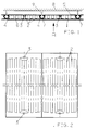
- a heat exchange element consists in particular of a metal plate 1 z. B. made of aluminum, in which flow channels 2 are integrated during the manufacturing process.
- a heat exchange medium flows through the flow channels 2. Cold or warm water is used as the heat exchange medium, depending on whether the heat exchange elements are used for cooling or for heating the room. By integrating the flow channels 2 into the metal plate 1, they have a very good thermal conductivity.
- the flow channels 2 are connected to the supply and discharge of the heat exchange medium with two nozzles 3, which are arranged within the heat exchange elements.
- the flow channels 2 are distributed over the entire surface of the metal plate 1 and are essentially parallel to one another. Starting from the connection piece 3, the flow channels 2 either run in a meandering shape or branch into several parallel strands.
- the individual heat exchange elements are connected to a manifold through which individual rooms, room groups or zones are supplied with the heat exchange medium.
- the metal plate 1 represents an unstable structure in itself. It is therefore provided with a reinforcement structure and thus forms a self-supporting component.
- the reinforcement structure can consist of a layer of rigid foam which is applied to one side of the metal plate 1.
- the hard foam layer also serves as insulation.
- the metal plate 1 containing the flow channels 2 is connected to a circumferential, self-contained frame 4.
- the frame 4 On the side facing away from the metal plate 1, the frame 4 is connected to a metal sheet 5.
- the connection to the frame 4 can be designed as a screw or rivet connection, or can be produced by gluing, soldering or welding.
- the space between the metal sheet 5 and the metal plate 1 is filled with insulation 6, which is used for heat or sound insulation. In the latter case, the metal plate 1 is perforated.
- the frame 4 has an undercut profile, into which holding rails 7 engage laterally.
- the holding rails 7 are fastened to the ceiling 8 of the room to be air-conditioned via brackets 9.
- the cross section of the holding rail 7 is adapted to the profile of the frame 4. 1, the holding rails 7 are diamond-shaped, while the profile of the frame 4 has an inwardly projecting right angle, at the legs of which two flanges are connected, with which the metal sheet 5 and the metal plate 1 are connected.
- This tongue and groove connection between the frame 4 and the holding rail 7 can also be formed in that the frame 4 has an outwardly curved profile which engages in a recess in the holding rail 7.
- the metal plate 1 of the heat exchange element can be coated with a plaster of plastic resin or mineral substances, provided with a coat of paint, or covered with textile materials made from natural products or synthetic fibers.
- the joined surface-shaped heat exchange elements thus form the ceiling or the wall of the room to be air-conditioned.
- the holding rails 7 can be mounted close to or at a distance from the ceiling 8. In the latter case, the heat exchange elements form a suspended ceiling.
- the heat exchange elements can be connected to similar elements, which serve as blind or closure elements, to form a closed ceiling. Like the heat exchange elements described, these similar elements consist of a metal plate facing the room, a frame, a metal sheet and an insulation in between. The only difference is that the metal plate has no flow channels.
- the ceiling elements such as lamps, loudspeakers, fire alarms or sprinkler elements, are inserted into the metal plate of the similar elements.
Landscapes
- Engineering & Computer Science (AREA)
- Mechanical Engineering (AREA)
- General Engineering & Computer Science (AREA)
- Chemical & Material Sciences (AREA)
- Combustion & Propulsion (AREA)
- Sustainable Development (AREA)
- Life Sciences & Earth Sciences (AREA)
- Architecture (AREA)
- Physics & Mathematics (AREA)
- Civil Engineering (AREA)
- Structural Engineering (AREA)
- Thermal Sciences (AREA)
- Electromagnetism (AREA)
- Devices For Blowing Cold Air, Devices For Blowing Warm Air, And Means For Preventing Water Condensation In Air Conditioning Units (AREA)
- Building Environments (AREA)
- Domestic Hot-Water Supply Systems And Details Of Heating Systems (AREA)
- Non-Reversible Transmitting Devices (AREA)
- Cooling Or The Like Of Electrical Apparatus (AREA)
- Heat-Exchange Devices With Radiators And Conduit Assemblies (AREA)
Claims (9)
- Système de climatisation, en particulier pour le refroidissement de locaux, avec un élément échangeur de chaleur planiforme, composé de canaux d'écoulement (2) destinés au guidage d'un fluide d'échange de chaleur et d'une plaque métallique (1), renforcée en vue de former un élément de construction autoporteur, caractérisé en ce que les canaux d'écoulement (2) sont intégrés dans la plaque métallique (1), en ce que, du côté opposé au local, la plaque métallique (1) est entourée par un cadre profilé (4), en ce qu'au plafond (8) du local sont disposées des glissières de fixation (7) et en ce que le cadre (4) et les glissières de fixation (7) s'engagent les uns dans les autres, le cadre (4) ou les glissières de fixation (7) présentant un profil doté d'une contre-dépouille.
- Système selon la revendication 1, caractérisé en ce que la plaque métallique (1) est pourvue d'une isolation (6), du côté opposé au local.
- Système selon la revendication 2, caractérisé en ce que l'isolation est réalisée en matériau alvéolaire dur.
- Système selon la revendication 1, caractérisé en ce que le cadre de pourtour (4) est relié à une tôle métallique (5).
- Système selon la revendication 4, caractérisé en ce que l'isolation est disposée entre la tôle métallique (5) et la plaque métallique (1).
- Système selon l'une des revendications 1 à 5, caractérisé en ce que l'élément échangeur de chaleur est recouvert d'un enduit en résine synthétique ou en substances minérales.
- Système selon l'une des revendications 1 à 6, caractérisé en ce que l'élément échangeur de chaleur est pourvu côté local d'une couche de peinture.
- Système selon l'une des revendications 1 à 6, caractérisé en ce que l'élément échangeur de chaleur est revêtu côté local de matériaux textiles à base de produits naturels ou de fibres synthétiques.
- Système selon l'une des revendications 1 à 8, caractérisé en ce que l'élément échangeur de chaleur fait partie d'un plafond suspendu.
Priority Applications (1)
| Application Number | Priority Date | Filing Date | Title |
|---|---|---|---|
| AT90124665T ATE100925T1 (de) | 1990-04-14 | 1990-12-19 | Flaechenfoermiges austauschelement. |
Applications Claiming Priority (2)
| Application Number | Priority Date | Filing Date | Title |
|---|---|---|---|
| DE4012134A DE4012134A1 (de) | 1990-04-14 | 1990-04-14 | Flaechenfoermiges waermeaustauschelement |
| DE4012134 | 1990-04-14 |
Publications (2)
| Publication Number | Publication Date |
|---|---|
| EP0452558A1 EP0452558A1 (fr) | 1991-10-23 |
| EP0452558B1 true EP0452558B1 (fr) | 1994-01-26 |
Family
ID=6404456
Family Applications (1)
| Application Number | Title | Priority Date | Filing Date |
|---|---|---|---|
| EP90124665A Expired - Lifetime EP0452558B1 (fr) | 1990-04-14 | 1990-12-19 | Elément échangeur planair |
Country Status (4)
| Country | Link |
|---|---|
| EP (1) | EP0452558B1 (fr) |
| AT (1) | ATE100925T1 (fr) |
| DE (2) | DE4012134A1 (fr) |
| ES (1) | ES2048400T3 (fr) |
Families Citing this family (11)
| Publication number | Priority date | Publication date | Assignee | Title |
|---|---|---|---|---|
| EP0555494A1 (fr) * | 1991-10-30 | 1993-08-18 | Uwe Klix | Radiateur avec gaine d'air |
| DE9209999U1 (de) * | 1992-07-24 | 1993-08-26 | Tever GmbH & Co KG, 83022 Rosenheim | Heiz- oder Kühlpaneel |
| DE9410565U1 (de) * | 1994-06-30 | 1994-11-17 | Wilhelmi Werke GmbH & Co KG, 35633 Lahnau | Akustikdecke |
| DE19500670C1 (de) * | 1995-01-11 | 1996-02-08 | Krantz Tkt Gmbh | Kühlvorrichtung |
| DE29517701U1 (de) * | 1995-11-08 | 1996-01-04 | Kühling & Hauers Schwimmbadtechnik GmbH, 30916 Isernhagen | Plattenförmiges Wärmestrahlungselement |
| DE29600420U1 (de) * | 1996-01-12 | 1996-03-21 | Begemann, Uwe, Dipl.-Ing., 49143 Bissendorf | Thermo-Element |
| EP1004827B1 (fr) * | 1998-11-23 | 2002-07-03 | Plan Holding GmbH | Panneau radiant, autoportant, modulaire et préfabriqué, procédé de fabrication et surface radiante ainsi obtenue |
| DE29913730U1 (de) | 1999-08-06 | 1999-11-11 | Spectral Gesellschaft für Lichttechnik mbH, 79111 Freiburg | Kühldecke zur Kühlung eines Raumes |
| CH706869A1 (de) * | 2012-08-21 | 2014-02-28 | Mwh Barcol Air Ag | Deckenelement für eine Heiz- oder Kühldecke. |
| DK3645946T3 (da) * | 2017-06-28 | 2021-07-12 | Price Industries Ltd | Termisk aktiveret byggepanel |
| DE102018216047A1 (de) * | 2018-09-20 | 2020-03-26 | Mahle International Gmbh | Kühlstruktur |
Family Cites Families (18)
| Publication number | Priority date | Publication date | Assignee | Title |
|---|---|---|---|---|
| DE1151363B (de) * | 1953-08-01 | 1963-07-11 | Albert Konanz Dipl Ing | Decken- und Wandheizungsanlage |
| GB1009332A (en) * | 1961-02-10 | 1965-11-10 | White & Co Ltd Samuel | Cooling trays and units |
| FR1506580A (fr) * | 1966-11-10 | 1967-12-22 | Nessi Freres & Cie | Perfectionnements aux plafonds chauffants ou rafraîchissants |
| FR1502591A (fr) * | 1966-12-07 | 1967-11-18 | Internat Environment Corp | Système à panneaux pour le chauffage ou le refroidissement des batiments |
| FR2093099A5 (fr) * | 1970-06-02 | 1972-01-28 | Tombu Gerard | |
| DE2035936A1 (de) * | 1970-07-20 | 1972-02-03 | Maschinenfabrik Wiesbaden GmbH, 6200 Wiesbaden-Dotzheim | Deckenstrahlplatte |
| CA1065219A (fr) * | 1975-05-02 | 1979-10-30 | Charles A. Kleine | Panneau echangeur de chaleur |
| CA1061774A (fr) * | 1976-12-07 | 1979-09-04 | R. Mark J. Cairenius | Panneaux muraux caloporteurs |
| SE402640B (sv) * | 1977-06-13 | 1978-07-10 | Norell B | Byggmodul for innertak med inbyggda vermeelement |
| AT361666B (de) * | 1978-09-12 | 1981-03-25 | Vmw Ranshofen Berndorf Ag | Waermetauscher fuer raeume, insbesondere fuss- bodenheizung |
| DE3003407A1 (de) * | 1980-01-31 | 1981-08-06 | Carlo Schaberger Sondermaschinenbau/Automationssysteme, 6500 Mainz | Verfahren zum herstellen einer gut waermeleitenden verbindung zwischen einer metallischen rohrleitung mit einem fluiden heiz- oder kuehlmedium und der aussenseite einer metallbehaelterwand |
| AT379011B (de) * | 1981-03-13 | 1985-11-11 | Kuebler Gerd Ing | Deckenstrahlungsheizung |
| DE3246541A1 (de) * | 1982-12-16 | 1984-06-20 | Reinhard 6911 Campione Hering | Verfahren zur herstellung von platten oder formkoerpern |
| DE3609186A1 (de) * | 1985-03-01 | 1987-09-24 | Manfred Dipl Ing Weber | Waermetauscher |
| DE3714623A1 (de) * | 1986-08-23 | 1988-03-03 | Sueddeutsche Kuehler Behr | Plattenwaermetauscher |
| EP0347416A1 (fr) * | 1987-02-13 | 1989-12-27 | Hans Josef May | Elements structuraux pour systemes de chauffage ou de refroidissement, et leur procede de fabrication |
| DE8809007U1 (de) * | 1988-07-13 | 1988-09-01 | Karl Kässbohrer Fahrzeugwerke GmbH, 7900 Ulm | Fahrzeug mit temperierten Innenflächen |
| DE8906539U1 (de) * | 1988-09-13 | 1989-08-31 | Klostermann, Harald, 5750 Menden | Deckenstrahlplatte |
-
1990
- 1990-04-14 DE DE4012134A patent/DE4012134A1/de not_active Withdrawn
- 1990-12-19 DE DE90124665T patent/DE59004437D1/de not_active Expired - Fee Related
- 1990-12-19 AT AT90124665T patent/ATE100925T1/de not_active IP Right Cessation
- 1990-12-19 EP EP90124665A patent/EP0452558B1/fr not_active Expired - Lifetime
- 1990-12-19 ES ES90124665T patent/ES2048400T3/es not_active Expired - Lifetime
Also Published As
| Publication number | Publication date |
|---|---|
| ATE100925T1 (de) | 1994-02-15 |
| DE59004437D1 (de) | 1994-03-10 |
| ES2048400T3 (es) | 1994-03-16 |
| DE4012134A1 (de) | 1991-10-17 |
| EP0452558A1 (fr) | 1991-10-23 |
Similar Documents
| Publication | Publication Date | Title |
|---|---|---|
| DE69806390T2 (de) | Selbsttragendes modulares vorgefertigtes Strahlungspanel, Verfahren zur Herstellung und dadurch hergestellte Strahlungsoberfläche | |
| EP0346529B1 (fr) | Fixation de tubes | |
| EP1521935A1 (fr) | Procede de production d'elements d'echangeur de chaleur, elements d'echangeur de chaleur et procede de montage de tels elements | |
| EP0452558B1 (fr) | Elément échangeur planair | |
| DE102005003996B4 (de) | Modularer Raum | |
| DE69920647T2 (de) | Strömungskanal | |
| EP0299909A1 (fr) | Plafond en plaques métalliques | |
| EP0927323B1 (fr) | Couvercle refroidisseur, elements de couvercle refroidisseur et d'armature tubulaire de refroidissement | |
| DE2255747A1 (de) | Traeger, insbesondere deckentraeger fuer gebaeude | |
| EP0112272A2 (fr) | Elément et procédé pour la fabrication de ledit élément | |
| WO2008107037A1 (fr) | Élément de plafond, de paroi ou de plancher | |
| DE3329789C2 (de) | Wärmegedämmte Vorhangfassade | |
| EP0023043A2 (fr) | Chauffage de surface | |
| DE102013208284A1 (de) | Wärmedämmplatte und Verfahren zur Montage von Leitungen | |
| DE19640514A1 (de) | Mehrschichtige Systembauplatten für Heiz- und Kühlflächen | |
| DE2702337A1 (de) | Flaechenhafter, wickelbarer waermetauscher | |
| DE3919143A1 (de) | Flaechenfoermiges waermeaustauschelement zum heizen und kuehlen von raeumen | |
| EP0150242B1 (fr) | Eléments de montage pour constituer un bâtiment, climatisé par ses parois | |
| EP0038490A1 (fr) | Appareil pour le transfert de chaleur ou de froid à un liquide de transport parcourant l'appareil | |
| EP0046972A2 (fr) | Panneau chauffant | |
| DE9418919U1 (de) | Kühldecke | |
| DE2718029C2 (de) | Als Wandelement ausgeführte flächige Heiz- oder Kühlplatte | |
| EP1703214B1 (fr) | Elément de chauffage ou de réfrigération pour une cloison sèche avec ossature | |
| DE1966975A1 (de) | Wand- oder fussbodenbelagplatte als vorgefertigte installationsplatte mit grundund deckplatte | |
| DE69708514T2 (de) | Modulare Klimatisierungsplatte |
Legal Events
| Date | Code | Title | Description |
|---|---|---|---|
| PUAI | Public reference made under article 153(3) epc to a published international application that has entered the european phase |
Free format text: ORIGINAL CODE: 0009012 |
|
| AK | Designated contracting states |
Kind code of ref document: A1 Designated state(s): AT BE CH DE ES FR GB GR IT LI LU NL |
|
| 17P | Request for examination filed |
Effective date: 19911204 |
|
| 17Q | First examination report despatched |
Effective date: 19920513 |
|
| RAP1 | Party data changed (applicant data changed or rights of an application transferred) |
Owner name: H.KRANTZ - TKT GESELLSCHAFT MIT BESCHRAENKTER HAFT |
|
| GRAA | (expected) grant |
Free format text: ORIGINAL CODE: 0009210 |
|
| AK | Designated contracting states |
Kind code of ref document: B1 Designated state(s): AT BE CH DE ES FR GB GR IT LI LU NL |
|
| REF | Corresponds to: |
Ref document number: 100925 Country of ref document: AT Date of ref document: 19940215 Kind code of ref document: T |
|
| GBT | Gb: translation of ep patent filed (gb section 77(6)(a)/1977) |
Effective date: 19940125 |
|
| REF | Corresponds to: |
Ref document number: 59004437 Country of ref document: DE Date of ref document: 19940310 |
|
| ET | Fr: translation filed | ||
| REG | Reference to a national code |
Ref country code: ES Ref legal event code: FG2A Ref document number: 2048400 Country of ref document: ES Kind code of ref document: T3 |
|
| ITF | It: translation for a ep patent filed | ||
| REG | Reference to a national code |
Ref country code: GR Ref legal event code: FG4A Free format text: 3010895 |
|
| PGFP | Annual fee paid to national office [announced via postgrant information from national office to epo] |
Ref country code: GR Payment date: 19940831 Year of fee payment: 5 Ref country code: BE Payment date: 19940831 Year of fee payment: 5 |
|
| PGFP | Annual fee paid to national office [announced via postgrant information from national office to epo] |
Ref country code: LU Payment date: 19940901 Year of fee payment: 5 |
|
| PGFP | Annual fee paid to national office [announced via postgrant information from national office to epo] |
Ref country code: FR Payment date: 19940905 Year of fee payment: 5 Ref country code: CH Payment date: 19940905 Year of fee payment: 5 |
|
| PGFP | Annual fee paid to national office [announced via postgrant information from national office to epo] |
Ref country code: GB Payment date: 19940919 Year of fee payment: 5 |
|
| PGFP | Annual fee paid to national office [announced via postgrant information from national office to epo] |
Ref country code: ES Payment date: 19940922 Year of fee payment: 5 |
|
| PLBE | No opposition filed within time limit |
Free format text: ORIGINAL CODE: 0009261 |
|
| STAA | Information on the status of an ep patent application or granted ep patent |
Free format text: STATUS: NO OPPOSITION FILED WITHIN TIME LIMIT |
|
| PGFP | Annual fee paid to national office [announced via postgrant information from national office to epo] |
Ref country code: AT Payment date: 19941212 Year of fee payment: 5 |
|
| PGFP | Annual fee paid to national office [announced via postgrant information from national office to epo] |
Ref country code: NL Payment date: 19941231 Year of fee payment: 5 |
|
| 26N | No opposition filed | ||
| PG25 | Lapsed in a contracting state [announced via postgrant information from national office to epo] |
Ref country code: LU Free format text: LAPSE BECAUSE OF NON-PAYMENT OF DUE FEES Effective date: 19951219 Ref country code: GB Effective date: 19951219 Ref country code: AT Effective date: 19951219 |
|
| PG25 | Lapsed in a contracting state [announced via postgrant information from national office to epo] |
Ref country code: ES Free format text: LAPSE BECAUSE OF THE APPLICANT RENOUNCES Effective date: 19951220 |
|
| PG25 | Lapsed in a contracting state [announced via postgrant information from national office to epo] |
Ref country code: LI Effective date: 19951231 Ref country code: CH Effective date: 19951231 Ref country code: BE Effective date: 19951231 |
|
| BERE | Be: lapsed |
Owner name: H. KRANTZ - TKT G.M.B.H. Effective date: 19951231 |
|
| PG25 | Lapsed in a contracting state [announced via postgrant information from national office to epo] |
Ref country code: GR Free format text: THE PATENT HAS BEEN ANNULLED BY A DECISION OF A NATIONAL AUTHORITY Effective date: 19960630 |
|
| PG25 | Lapsed in a contracting state [announced via postgrant information from national office to epo] |
Ref country code: NL Effective date: 19960701 |
|
| GBPC | Gb: european patent ceased through non-payment of renewal fee |
Effective date: 19951219 |
|
| REG | Reference to a national code |
Ref country code: CH Ref legal event code: PL |
|
| PG25 | Lapsed in a contracting state [announced via postgrant information from national office to epo] |
Ref country code: FR Effective date: 19960830 |
|
| REG | Reference to a national code |
Ref country code: GR Ref legal event code: MM2A Free format text: 3010895 |
|
| NLV4 | Nl: lapsed or anulled due to non-payment of the annual fee |
Effective date: 19960701 |
|
| PGFP | Annual fee paid to national office [announced via postgrant information from national office to epo] |
Ref country code: DE Payment date: 19960911 Year of fee payment: 7 |
|
| REG | Reference to a national code |
Ref country code: FR Ref legal event code: ST |
|
| PG25 | Lapsed in a contracting state [announced via postgrant information from national office to epo] |
Ref country code: DE Free format text: LAPSE BECAUSE OF NON-PAYMENT OF DUE FEES Effective date: 19980901 |
|
| REG | Reference to a national code |
Ref country code: ES Ref legal event code: FD2A Effective date: 20010402 |
|
| PG25 | Lapsed in a contracting state [announced via postgrant information from national office to epo] |
Ref country code: IT Free format text: LAPSE BECAUSE OF NON-PAYMENT OF DUE FEES;WARNING: LAPSES OF ITALIAN PATENTS WITH EFFECTIVE DATE BEFORE 2007 MAY HAVE OCCURRED AT ANY TIME BEFORE 2007. THE CORRECT EFFECTIVE DATE MAY BE DIFFERENT FROM THE ONE RECORDED. Effective date: 20051219 |